MARINE RADAR
MODEL 851
MARINE RADAR
MODEL 851

C
9 - 5 2 , A s h i h a r a - c h o , N i s h i n o m i y a , J a p a n
A l l r i g h t s r e s e r v e d .  Printed in Japan
P U B . N o . O M E - 3 4 9 0 0
 Y o u r L o c a l A g e n t / D e a l e r

 SAFETY INSTRUCTIONS
 WARNING
 WARNING
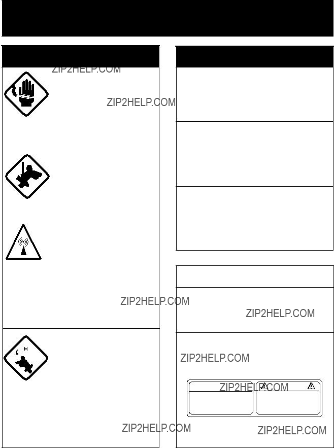
Do not disassemble or modify the equipment.
Fire, electrical shock or serious injury can result.
Turn off the power immediately if water leaks into the equipment or the equipment is emitting smoke or fire.
Fire or equipment damage can result if a different cable is used.
Keep heater away from equipment.
Heat can alter equipment shape and melt the power cord, which can cause fire or electrical shock.
 CAUTION
Use the proper fuse.
Use of a wrong fuse can result in fire or permanent equipment damage.
A warning label is attatched to the display unit. Do not remove the label. If the label is missing or damaged, contact a FURUNO agent or dealer.
 WARNING
To avoid electrical shock, do not remove cover.
No
Name: Warning Label (2)
Type:
Code No.:
i

TABLE OF CONTENTS
3.INTERPRETING THE DISPLAY
3.1The Radar Wave and Radar
ii
iii

FOREWORD
Congratulations on your choice of the FURUNO Marine Radar MODEL 851
For over 50 years FURUNO Electric Company has enjoyed an enviable reputation for innovative and dependable marine electronics equipment. This dedication to excellence is furthered by our extensive global network of agents and dealers.
Your radar is designed and constructed to meet the rigorous demands of the marine environment. However, no machine can perform its intended function unless properly installed and maintained. Please carefully read and follow the recommended procedures for installation, operation and maintenance.
While this unit can be installed by the purchaser, any purchaser who has doubts about his or her technical abilities may wish to have the unit installed by a FURUNO representative or other qualified technician. The importance of a thorough installation cannot be overemphasized.
We would appreciate hearing from you, the
Thank you for considering and purchasing FURUNO equipment.
Features
Your radar has a large variety of functions, all contained in a remarkably small cabinet.
The main features of the MODEL 851
???Traditional FURUNO reliability and quality in a compact, lightweight and
???Smartly styled,
???Durable brushless antenna motor.
???High definition 8" LCD
???
???Standard features include EBL (Electronic Bearing Line), VRM (Variable Range Marker), Guard Alarm, Display Off Center and Echo Trail.
???Watchman feature periodically transmits the radar to check for radar targets which may be entering (or exiting) the alarm zone.
???Ship???s position in latitude and longitude (or Loran C Time Differences), range and bearing to a waypoint, ship???s speed, heading and course can be shown in the bottom text area. (Requires a navigation aid which can output such data in NMEA 0183 format.)
???Zoom feature provided.
???Omnipad makes the selection of target and menu items easy.
iv

SYSTEM CONFIGURATION
Antenna unit
v

1. PRINCIPLE OF OPERATION
1.1 What is Radar?
The term "RADAR" is an acronym meaning RAdio Detection And Ranging. It is a device which measures the time it takes for a pulsed signal to be reflected back from an object.
1.2How Ships Determined Position Before Radar
The use of echoes to determine position did not begin with radar. Ships would sound a short blast on their whistles, fire a shot, or strike a bell as an aid to navigation when running in fog near a rugged shoreline. The time between the origination of the sound and the returning of the echo indicated how far the ship was from the cliffs or the shore. The direction from which the echo was heard indicated the relative bearing of the shore.
1.3How Radar Determines Range
Radar determines the distance to the target by calculating the time difference between the transmission of a radar signal and the reception of the reflected echo. It is a known fact that radar waves travel at a nearly constant speed of 162,000 nautical miles per second. Therefore the time required for a transmitted signal to travel to the target and return as an echo to the source is a measure of the distance to the target. Note that the echo makes a complete round trip, but only half the time of travel is needed to determine the one- way distance to the target. This radar automatically takes this into account in making the range calculation.
1.4How Radar Determines Bearing
The bearing to a target found by the radar is determined by the direction in which the radar antenna is pointing when it emits an electronic pulse and then receives a returning echo. Each time the antenna rotates pulses are transmitted in the full 360 degree circle, each pulse at a slightly different bearing from the previous one. Therefore, if one knows the direction in which the signal is sent out, one knows the direction from which the echo must return.

1.5Radar Wave Speed and Antenna Rotation Speed
The speed of the radar waves out to the target and back again as echoes is extremely fast compared to the speed of rotation of the antenna. By the time radar echoes have returned to the antenna, the amount of antenna rotation after initial transmission of the radar pulse is extremely small.
1.6 The Radar Display
Targets are displayed on what is called a Plan Position Indicator (PPI). This display is essentially a polar diagram, with the transmitting ship???s position at the center. Images of target echoes are received and displayed at their relative bearings, and at their distance from the PPI center.
With a continuous display of the images of targets, the motion of the transmitting ship is also displayed.
A
Targets
 DA
DA
Heading marker
B
CB
Own ship (radar)
C
Own ship in center
Figure

2. OPERATION
2.1 Control Description
Omnipad
Shifts cursor, VRM and EBL; selects items and options on menu.
OFF Sets guardGUARD CENTER zone area.
Erases heading marker;
selects cursor data (Lat/Long, R/B); outputs cursor position.
Selects radar range.
Adjusts display brilliance.
Turns the VRM on/off.
Turns the range rings on/off.
Off centers the display.
Sets radar in
Figure
2.2 Display Indications and Markers
Figure
2.3Turning the Radar On and Off
Press the [POWER] key to turn the radar on or off. The control panel lights and a timer displays the time remaining for warm up of the magnetron (the device which produces radar pulses), counting down from 1:30.
Note: When the power is reapplied within a certain amount of time and circuits remain charged, the warmup process is
!WARNING
The radar antenna emits high frequency radio radiation which can be harmful, particularly to your eyes. Never look directly at the antenna from a distance of less than three feet when the radar is in operation. Always make sure no one is near the antenna before turning on the radar.

Note: When the heading signal is lost, the HDG readout at the top of the screen shows ***.*. This warning stays on when the heading signal is restored to warn the operator that the readout may be unreliable. After confirming the heading readout (if necessary, adjust it), the warning may be erased by pressing the [DISP MODE] key.
Tips for selecting the range
???When navigating in or around crowded harbors, select a short range to watch for possible collision situations.
???If you select a lower range while on open water, increase the range occasionally to watch for vessels that may be heading your way.
2.4 Transmitting
After the power is turned on and the magnetron has warmed up,
Press the
When you won???t be using the radar for an extended period but want to keep it in a state of readiness, press the
2.5 Selecting the Range
The range selected automatically determines the range ring interval, the number of range rings, pulselength and pulse repetition rate, for optimal detection capability in short to long ranges.
Procedure
Press the [??? RANGE +] key. The range and range ring interval appear at the top left corner on the display.
2.6Adjusting LCD Backlighting and Display Tone
The [BRILL] key adjusts the LCD backlighting in eight levels, including off. The [TONE] key adjusts the tone (contrast) of the display in 32 levels, including off.
Procedure
1.Press the [BRILL] key (or [TONE] key). The display shown in Figure
BRILL
UP
Figure
2.Press the [BRILL] key (or [TONE] key) to set level. For fine adjustment, press omnipad at 12 o'clock/6 o'clock for brilliance and 3 o'clock/9 o'clock for tone.

2.7 Adjusting Control Panel
Illumination
Procedure
1.Press the [MENU] key.
2.Press the omnipad at 6 o???clock to select Backlight/Brilliance and press the [ENT] key.
3.Press the omnipad at 6 o???clock to select Panel.
4.Press the omnipad at 3 o???clock/9 o???clock to select illumination level; 4 is the highest.
5.Press the [ENT] key followed by the [MENU] key.
2.8 Adjusting GAIN, STC, A.C
RAIN and FTC
General procedure
The [ECHO] key enables adjustment of the GAIN, STC, A.C RAIN and FTC.
1.Press the [ECHO] key. The following display appears.
omnipad arrow.
Figure
2.Press the omnipad at 6 o???clock/12 o???clock to select item to adjust. Current selection is circumscribed by dashed rectangle.
3.Press the [ENT] key.
4.Press the omnipad at 3 o???clock/9 o???clock to set level.
5.Press the [ECHO] key to finish.
How to adjust the GAIN (sensitivity)
The GAIN works in precisely the same manner as the volume control of a broadcast receiver, amplifying the signals received.
You can adjust the GAIN automatically or manually. If you select AUTO, the GAIN automatically adjusted. The range of the GAIN adjustment is from 1 to 3; 3 is the highest. For manual adjustment, adjust the sensitivity on the highest
On the contrary excessive GAIN yields too much background noise; strong targets may be missed because of the poor contrast between desired echoes and the background noise on the display.
How to adjust STC (suppressing sea clutter)
Echoes from waves can be troublesome, covering the central part of the display with random signals known as sea clutter. The higher the waves, and the higher the antenna above the water, the further the clutter will extend. Sea clutter appears on the display as many small echoes which might affect radar performance. (See the
The STC reduces the amplification of echoes at short ranges (where clutter is the greatest) and progressively increases amplification as the range increases, so amplification will be normal at those ranges where there is no sea clutter. The control is effective up to about 4 miles.
STC can be adjusted automatically or manually. If you select AUTO, the STC automatically adjusted. The range of STC adjustment is from 1 to 3; 3 is the highest. For manual adjustment, first adjust the gain and then transmit on short range. The range of STC adjustment is from 00 to 50. Adjust the STC level such that the clutter is broken up into small dots, and small targets become distinguishable. If the setting is set too low, targets will be hidden in the clutter, while if it is set too high, both sea clutter and targets will disappear from the display. In most cases adjust so clutter has disappeared to leeward, but a little is still visible windward.
If there is no clutter visible on the display, turn off the circuit.
Figure
How to adjust A.C RAIN and FTC (suppressing rain clutter)
The vertical beamwidth of the antenna is designed to see surface targets even when the ship is rolling. However, by this design the unit will also detect rain clutter (rain, snow, hail, etc.) in the same manner as normal targets. Figure
Adjusting A.C RAIN
When rain clutter masks echoes over a wide range, raise the A.C RAIN slightly to distinguish targets from the clutter.
Figure

Adjusting FTC
To suppress rain clutter from heavy storms or scattered rain clutter, adjust the FTC among 0, 1 and 2 (0 is off). The FTC circuit splits up these unwanted echoes into a speckled pattern, making recognition of solid targets easier. FTC and selected level appear at the top
Note: In addition to reducing clutter, the FTC can be used in fine weather to clarify the picture when navigating in confined waters. However, with the circuit activated the receiver is less sensitive. Therefore, turn off the circuit when its function is not required.
2.9 Tuning the Receiver
The receiver can be tuned automatically or manually. For automatic tuning the receiver is tuned each time you switch from stand- by to transmit. For manual tuning, the receiver is properly tuned when the longest tuning indicator appears. (However, the length of the indicator changes with the number of radar echoes, range and other factors.)
0.5
Figure
Note:When you switch from manual to automatic, wait 4 seconds before closing the MENU. Otherwise automatic tuning may not work properly.
Manual tuning
The default tuning method is automatic. To switch to manual tuning;
1.Press the [MENU] key to open the menu.
2.Press the omnipad at 6 o???clock to select Tuning.
3.Press the omnipad at 3 o???clock to select MANUAL.
4.Press the [ENT] key followed by the [MENU] key.
How to tune manually
While pressing and holding down the [HM OFF] key, press the 9 o'clock or 3 o'clock position on the omnipad to tune. Tune to show the longest tuning indicator.
2.10 Measuring the Range
You can measure the range to a target three ways: by the range rings, by the cursor, and by the VRM (Variable Range Marker).
By range rings
Press the [RINGS] key to display the range rings. Count the number of rings between the center of the display and the target. Check the range ring interval (at the top left corner) and judge the distance of the echo from the inner edge of the nearest ring.
By cursor
Operate the omnipad to place the cursor intersection on the inside edge of the target echo. The range to the target, as well as the bearing, appears at the bottom of the display.

By VRM
1.Press the [VRM] key to display the VRM.
2.Press the omnipad to place the VRM on the inside edge of the target.
3.Check the VRM readout at the bottom
Note: The VRM is automatically anchored if the omnipad is not operated within about 10 seconds.
To erase the VRM, press and hold down the [VRM] key for about two seconds.
1.5NM
0.5
Target
VRM 
Figure
2.11 Measuring the Bearing
There are two ways to measure the bearing to a target: by the cursor, and by the EBL (Electronic Bearing Line).
By cursor
Operate the omnipad to bisect the target with the cursor intersection. The bearing to the target appears at the bottom
By EBL
1.Press the [EBL] key to display the EBL.
2.Press the omnipad to bisect the target with the EBL.
3.Check the EBL readout at the bottom
Note: The EBL is automatically anchored if the omnipad is not operated within about 10 seconds.
To erase the EBL, press and hold down the [EBL] key for about two seconds.
1.5NM
0.5
Target
EBL
 EBL bearing
Figure

Tips for measuring the bearing
???Bearing measurements of smaller targets are more accurate; the center of larger target echoes is not as easily identified.
???Bearings of stationary or slower moving targets are more accurate than bearings of faster moving targets.
???To minimize bearing errors keep echoes in the outer half of the picture by changing the range scale; angular difference becomes difficult to resolve as a target approaches the center of the display.
Target on Collision course with your vessel?
You can determine if a target might be on a collision course with your vessel by placing the EBL on the target. If it tracks along the EBL as it approaches the screen center it may be on a collision course with your vessel.
2.12 Menu Operation
The menu, consisting of six sub menus, mostly contains
Basic menu operation
1.Press the [MENU] key to open the main menu.
??? MAIN MENU ???
Select item by ?????? keys and press ENT key.
1.Backlight/Brilliance
2.P/L, IR, NR & Radar Mode
3.Nav Data
4.Mode & Function
6.Self Check
7.Installation Setup 1
. . . . . . . . . . . . . . . . . . .
Press
<Press MENU key to escape>
Figure
2.Press the omnipad at 6 o???clock/12 o???clock to select menu and press the [ENT] key.
3.Press the omnipad at 6 o???clock/12 o???clock to select a menu item.
4.Press the omnipad at 3 o???clock/9 o???clock to select an option.
5.Press the [ENT] key to register selection.
6.Press the [MENU] key to close the menu.

Menu description
Table

2.13Selecting the Display Mode
The display mode may be selected with the [DISP MODE] key. Four modes are available (with navigation input): Normal, Normal + Window, Normal + Nav Data, and Normal + Window + Nav Data.
Each time the key is pressed the display mode changes in one of the sequences shown below, depending on equipment connected and menu settings.
Window display (Zoom or Wide)
ZOOM
Nav data
Figure

2.14 The Window Display
The window display appears at the bottom left (or right) 1/4 of the display. Two types of window displays are available: zoom and wide. Zoom doubles the size of the area selected by the operator, and wide (range- up) compresses and displays the entire radar picture from the next higher range.
Note 1: The zoom display does not function on the 0.125 and 0.25 nm ranges.
3.Press the [ENT] key to confirm the zoom area in the window display. The area selector becomes a dashed circle and the cursor can be moved independently.
To reselect area to zoom, press [ENT] or [DISP MODE] and follow steps 2 and 3.
Area selector (1/4 or 1/3 of range)
Note 2: The wide display does not function on the 48 nm range.
Selecting the type of window display
Window display area
(1) Press [DISP MODE] to select the window display.
(2) Use the omnipad to select area to zoom and press [ENT].
1.Press the [MENU] key.
2.Press the omnipad at 6 o???clock to select Mode & Function and press the [ENT] key.
3.Press the omnipad at 6 o???clock to select Window Display to Zoom or Wide as appropriate.
4.Press the [ENT] key followed by the [MENU] key.
Selecting the area for the zoom picture
1.Press the [DISP MODE] key to select the window display. The area selector, a solid circle, appears.
2.Use the omnipad to place the area selector on the area to zoom.
Note: When you place the area selector behind the window display, the window display shifts right (or left) so you may view the circle cursor.
Figure
Figure
2.15Selecting the Presentation Mode
This radar provides four presentation modes:
Note: TM does not function on the 48 nm range.
CU
Selecting
You may select
CU
An azimuth stabilized display in which a line connecting the center with the top of the display indicates own ship???s intended course (namely, own ship???s previous heading just before this mode has been selected).
Target pips are painted at their measured distances and in their directions relative to the intended course which is maintained at the
An azimuth stabilized display in which the line connecting the center with the top of the display indicates the bearing to the ???TO??? waypoint, which is selected on the navigational equipment connected to the radar. When navigating a route and own ship enters the arrival zone of a waypoint, the radar displays the bearing to the next ???TO??? waypoint.
Procedure
1.Press the [MENU] key to open the menu.
2.Press the omnipad at 6 o???clock to select 2. P/L, IR, NR & Radar Mode.
3.Press the [ENT] key.
4.Press the omnipad at 6 o???clock to select Radar Mode.
5.Press the omnipad at 3 o???clock/9 o???clock to select the option CU or
6.Press the [ENT] key followed by the [MENU] key.
2.16 Guard Alarm
The guard alarm allows the operator to set the desired range and bearing for a guard zone. When ships, islands, landmasses, etc. enter (or exit, depending on type of guard zone in use) the guard zone an audible alarm sounds to call the operator???s attention. The alarm is very effective as an anticollision aid when using an autopilot or navigating in narrow channels.
 CAUTION
The guard alarm is a useful
Selecting guard zone type
The guard alarm can be set to sound on targets entering (guard in) or exiting (guard out) the guard zone. Select type of guard zone as follows.
1.Press the [MENU] key to display the menu.
2.Press the omnipad at 6 o???clock to select Mode & Function and press the [ENT] key.
3.Press the omnipad at 6 o???clock to select Alarm Mode.
4.Press the omnipad at 3 o???clock/9 o???clock to select IN or OUT as appropriate.
5.Press the [ENT] key followed by the [MENU] key.
Dashed line: no alarm
Guard  zone
zone
Figure
Setting the guard zone
1.Mentally create the guard zone you want to display. See Figure
2.Operate the omnipad to set cursor on top (bottom) left edge of the guard zone. Press the [GUARD] key. *G (IN) (or G (OUT)), with asterisk blinking, appears at the top
3.Operate the omnipad to set cursor on bottom (top) right edge of the guard zone and press the [GUARD] key. The asterisk disappears. See Figure
(3).
4.Guard zone appears on the display. See Figure
Silencing the audible alarm
Any ships, landmasses, etc. coming into (or going out of) the guard zone will trigger the audible alarm and display the guard zone in reverse video. You can silence the alarm by pressing the [GUARD] key. When this is done, G (ACKN) replaces G (IN) (or G (OUT)).
Press the [GUARD] key again to reactivate the alarm. G (IN) (or G (OUT)) replaces G (ACKN).

Canceling the guard zone
Press and hold down the [GUARD] key until the guard zone disappears.
Notes on the guard alarm
???When the radar range is less than one half of the guard zone range, the guard zone disappears from the display and G (IN) (or G (OUT)) is displayed in reverse video. If this happens, raise the range to redisplay the guard zone.
???A target echo does not always mean a landmass, reef, ships or surface objects but can imply returns from sea surface or precipitation. As the level of these returns varies with environment, the operator should properly adjust the STC, GAIN (sensitivity), A. C RAIN and FTC to be sure the alarm system does not overlook target echoes.
Figure
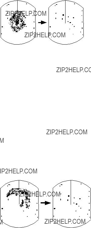
2.17Suppressing Radar Interference
Radar interference may occur when near another shipborne radar operating in the same frequency band as your radar. Its on- screen appearance is many bright dots either scattered at random or in the form of dotted lines extending from the center to the edge of the display. Figure
Figure
Four levels of interference are available, including off. 3 provides the highest level of rejection.
Procedure
1.Press the [MENU] key.
2.Press the omnipad at 6 o???clock to select P/L, IR, NR & Radar Mode and press the [ENT] key.
3.Press the omnipad at 6 o???clock to select Int Reject.
4.Press the omnipad at 3 o???clock/9 o???clock to select level desired; 3 provides the greatest degree of interference rejection.
5.Press [ENT] and [MENU] keys.
IR appears at the top right corner on the display when the interference rejection circuit is turned on.

2.18Suppressing Noise Interference
Noise interference appears on the screen as many bright dots. These dots can be suppressed by turning on the noise rejector. Note however that there are some forms of noise interference which this radar cannot suppress.
Procedure
1.Press the [MENU] key.
2.Press the omnipad at 6 o???clock to select P/L, IR, NR & Radar Mode and press the [ENT] key.
3.Press the omnipad at 6 o???clock to select Noise Reject.
4.Press the omnipad at 3 o???clock/9 o???clock to select ON or OFF as appropriate.
5.Press the [ENT] key followed by the [MENU] key.
2.19 Selecting Pulselength
Pulselength is the transmission time of a single radar pulse. The longer the pulselength the greater the detection range capability, however range accuracy and range resolution are reduced.
Pulselength can be selected to short or long on the 1.5 and 3 nautical mile ranges.
1.Press the [MENU] key.
2.Press the omnipad at 6 o???clock to select P/L, IR, NR & Radar Mode and press the [ENT] key.
3.Press the omnipad at 6 o???clock to select Pulselength.
4.Press the omnipad at 3 o???clock/9 o???clock to select SHORT or LONG as appropriate.
5.Press [ENT] and [MENU] keys.
SP or MP for 1.5 NM range, or MP or LP for 3 NM range appears at the upper
2.20 Off Centering the Display
Note: This function is not available on the 48 nm range.
Your vessel???s position can be shifted anywhere in the effective display area. The primary advantage of the off centered display is that for any range setting, the view ahead of your vessel can be extended without changing the range or size of targets.
Procedure
1.Locate the cursor where you want to the screen center to be.
2.Press the [OFF CENTER] key.
OFF CENTER appears at the top left corner on the display when the display is off centered.
3.To cancel the off center display, press the [OFF CENTER] key again.
(1) Place cursor (2) Press [OFF CENTER] key; where desired. cursor location becomes
own ship's position.
Figure

2.21 Echo Trails
You can show the trails of targets in afterglow. This function is useful for alerting you to possible collision situations.
Starting echo trail
Press the [TRAIL] key to start the echo trail function. Afterglow starts extending from targets and "TRAIL" and the echo trail time appear at the top
Note: If the range is changed, trails are painted anew with the newly selected range.
Figure
Fixed time trails
When the elapsed time clock counts up to the trail time selected, the elapsed time display freezes. The oldest portions of trails are erased so only the latest trail, equal in length to the trail time selected, is shown. Then, trails start extending again. For example, the one minute trail time is selected. When the elapsed time display freezes at 60 seconds, all but the latest one minute of trails are erased and then trailing continues.
Continuous trail
The maximum continuous trail time is 99 minutes and 59 seconds. When the elapsed time clock counts up to that time the elapsed time display is reset to zero, all trails are erased and then trailing is restarted.
Adjusting brilliance of afterglow
The brilliance of the trails' afterglow can be set on the Backlight/Brilliance menu.
1.Press the [MENU] key.
2.Press the omnipad at 6 o???clock to select Backlight/Brilliance and press the [ENT] key.
3.Press the omnipad at 6 o???clock to select Echo Trail.
4.Select brilliance level, 1 or 2 as desired. 2 is the highest level.
5.Press the [ENT] key followed by the [MENU] key.
Canceling echo trails
Press the [TRAIL] key to erase the TRAIL indication.

2.22 Navigation Data Display
Navigation data can be displayed at the screen bottom if this radar receives appropriate navigation input in NMEA 0183 format. Navigation data includes
???Position in latitude and longitude or
???Bearing and range to a waypoint selected on the navigator
???Cross track error
???Depth
???Speed
If the navigation data includes the destination data, waypoint position is denoted on the radar display by a dashed ring.
Waypoint position
Figure
Setting up the nav data display
1.Press the [MENU] key.
2.Press the omnipad at 6 o???clock to select Nav Data and press the [ENT] key.
??? NAV DATA MENU ???
. . . . . . . . . . . . . . . . . . .
Press
<Press MENU for main menu.>
Figure
3.Press the omnipad at 6 o'clock to select Navigator.
4.Press the omnipad at 3 o'clock/9 o'clock to select ALL, GPS or LC as appropriate and press the [ENT] key. (Select ALL if several navigators are connected to the radar. In this case, position data is selected in order of GPS, Loran C and other.)
5.Press the omnipad at 6 o'clock to select Nav Data Disp.
6.Press the omnipad at 3 o'clock/9 o'clock to select ON or OFF as appropriate and press the [ENT] key.
7.Press the omnipad at 6 o'clock to select Pos Disp Mode.
8.Press the omnipad at 3 o'clock/9 o'clock to select L/L (latitude and longitude) or TD (Loran C) as appropriate and press the [ENT] key.
9.Press the omnipad at 6 o'clock to select Depth Unit.

10.Press the omnipad at 3 o'clock/9 o'clock to select M (meters), FA (fathoms) or FT (feet) as desired and press the [ENT] key.
11.Press the omnipad at 6 o'clock to select Temp Unit.
12.Press the omnipad at 3 o'clock/9 o'clock to select ??C or ??F as desired and press the [ENT] key.
13.Press the omnipad at 6 o'clock to select STBY Display.
14.Press the omnipad at 3 o'clock/9 o'clock to select NORM (navigational data is not displayed) or NAV (navigational data is displayed as desired) and press the [ENT] key.
15.Press the [MENU] key to escape.
2.23Echo Stretch (magnifying long range echoes)
Normally, the reflected echoes from long range targets appear on the display as weaker and smaller blips even though they are compensated by the radar???s internal circuitry. To stretch long range echoes, in the range direction, turn on the echo stretch function.
Distant echo
Turning echo stretch on or off
1.Press the [MENU] key.
2.Press the omnipad at 6 o???clock to select P/L, IR, NR & Radar Mode and press the [ENT] key.
3.Press the omnipad at 6 o???clock to select Echo Stretch.
4.Press the omnipad at 3 o???clock/9 o???clock to select ON or OFF as appropriate.
5.Press the [ENT] key followed by the [MENU] key. ES appears at the top right side on the display when the echo stretch feature is on.
Note 1: This function magnifies not only targets but also sea clutter and radar interference. For this reason be sure the controls for adjustment of sea clutter and radar interference are properly adjusted before activating the echo stretch.
Note 2: Echo stretch is inoperative on ranges from 0.125 to 0.5 nautical miles.
Note 3: When the echo stretch function is selected, the equipment automatically selects interference rejection level #3 and turns on the noise rejector. These can be turned off via the menu if desired.
Figure

2.24Selecting Unit of Measurement for Range
The unit of measurement for the VRM and cursor can be nautical miles, kilometers, or statute miles. You may select unit desired as follows.
1.Press the [MENU] key.
2.Press the omnipad at 6 o???clock to select Mode & Function and press the [ENT] key.
3.Press the omnipad at 6 o???clock to select VRM Unit.
4.Press the omnipad at 3 o???clock/9 o???clock to select NM, KM, or SM as desired.
5.Press [ENT] followed by [MENU] key.
2.25Selecting Bearing Reference
Bearing can be displayed relative to ship???s heading (relative bearing) or relative to true north (true bearing) as follows. (True bearing requires heading sensor input.)
1.Press the [MENU] key.
2.Press the omnipad at 6 o???clock to select Mode & Function and press the [ENT] key.
3.Press the omnipad at 6 o???clock to select EBL Ref.
4.Press the omnipad at 3 o???clock/9 o???clock to select REL(ATIVE) or TRUE as appropriate.
5.Press the [ENT] key followed by the [MENU] key.
2.26 Watchman
How watchman works
The watchman function periodically transmits the radar for about one minute to check for targets in a guard zone. If it finds change in the zone from the previous transmission it sounds the aural alarm, cancels the watchman function, and transmits the radar continuously. This feature is useful when you do not need the radar???s function continuously but want to be alerted to radar targets in a specific area.
Watchman starts.
Figure
Turning on watchman
1.Create a guard zone (usually 360 degrees) with the guard alarm function.
2.Press the [MENU] key.
3.Press the omnipad at 6 o???clock to select Mode & Function and press the [ENT] key.
4.Press the omnipad at 6 o???clock to select Watchman.
5.Press the omnipad at 3 o???clock/9 o???clock to select watchman rest interval (amount of time until next rotation of antenna); 5 minutes, 10 minutes or 20 minutes as desired.
6.Press the [ENT] key followed by the [MENU] key. Then, WATCHMAN appears, and the radar transmits for one minute and then goes into stand- by.

Canceling watchman
1.Press the [MENU] key.
2.Press the omnipad at 6 o???clock to select Mode & Function and press the [ENT] key.
3.Press the omnipad at 6 o???clock to select Watchman.
4.Press the omnipad at 3 o???clock/9 o???clock to select OFF.
5.Press the [ENT] key followed by the [MENU] key.
2.27Erasing the Heading Marker
The heading marker continuously appears on the display and shows your vessel???s heading. When this mark obscures a target echo, you can temporarily erase it by pressing and holding down the [HM OFF] key. Release the key to redisplay the marker.
2.28 Deselecting Ranges
This radar has 16 ranges, some which you may not require. You can deselect up to fourteen ranges as follows.
1.Press the [MENU] key.
2.Press the omnipad at 6 o???clock to select Mode & Function and press the [ENT] key.
3.Select Range and press the [ENT] key. Active ranges appear in reverse video.
4.Press the omnipad at 3 o???clock/9 o???clock to select range to disable (or enable) and press the [ENT] key. Current selection is underlined.
5.Press the [ENT] key.
6.Repeat steps 4 and 5 to disable (or enable) other ranges.
7.When finished, press the [MENU] key.
2.29Displaying Navigation Data During
Various navigation data can be displayed during
 CAUTION
The barometer and depth displays are intended as reference. Any data displayed by them should be used with extreme caution.
Procedure
1.Press the [MENU] key.
2.Press the omnipad at 6 o???clock to select the Nav Data and press the [ENT] key.
3.Press the omnipad at 6 o???clock to select STBY Display.
4.Press the omnipad at 3 o???clock/9 o???clock to select NAV and press the [ENT] key.
5.Press the [MENU] key.

Note 1: The depth display scale changes automatically with depth and the maximum depth is 1,000 meters.
Note 2: The barometer display is updated hourly, thus the data shown may not be the latest.
Figure
2.30Outputting Cursor Position to Navigator
Cursor position (NMEA0183 data sentence TLL) can be output to the navigator connected to this radar by pressing and holding down the [HM OFF] key.
2.31Displaying Cursor Position, Range and Bearing to Cursor
The cursor data indication at the bottom of the display can show cursor position in latitude and longitude or the range and bearing from own ship to the cursor. You can select the indication desired by pressing the [HM OFF] key.
Navigation data is required to display latitude/longitude position.
2.32 Visual Alarm Indications
This radar display various visual alarms to alert you to error.
Table
The heading signal visual alarm may be cleared by pressing the [DISP MODE] key.
3. INTERPRETING THE DISPLAY
As an aid to navigation, radar can be a very valuable tool. No other electronic navigation aid can give you the ability to spot vessels coming at you in the fog, or tell you the location of the inlet to the harbor in the pitch black of night.
To help you understand what your radar can (and cannot) do for you this chapter covers
???the characteristics of the radar wave
???target properties and radar wave reflection
???range and bearing resolution, and
???false echoes.
3.1 The Radar Wave and Radar
Horizon
How the radar wave travels
The radar wave tends to travel in straight lines at the speed of light. However, it is subject to bending or refraction in the atmosphere, the amount depending on region and density.
Radar horizon
Radar is essentially a
The distance to the horizon from the antenna, under normal conditions, is calculated by the following formula.
Rmax = 2.2 ??? h1 + h2
Where Rmax: Radar horizon (mile), h1:
Antenna height (meters), h2: Target height (meters)
Figure

3.2Target Properties and Radar Wave Reflection
Generally, larger targets can be seen on the radar display at greater ranges, provided
A ship whose hull is made of conducting materials, such as steel, will return a relatively strong echo.
On the other hand, hulls made from wood or fiberglass return much weaker echoes.
Vertical surfaces, such as a cliff, are good targets provided they face the radar. Conversely, horizontal and smooth surfaces such as mudbanks, sandy beaches, and gently sloping hills make poor targets because they disperse rather than reflect most of the energy that strikes them.
The strongest radar echoes known come from
3.3 Range Resolution
Range resolution is a measure of the capability of a radar to display as separate pips the echoes received from two targets which are on the same bearing and are close together.
The main factor which affects range resolution is pulselength. Two targets on the same bearing, close together, cannot be seen as two distinct echoes on the display unless they are separated by a distance greater than
Radar cannot display targets as  separate echoes because they
are within the pulselength.
Figure
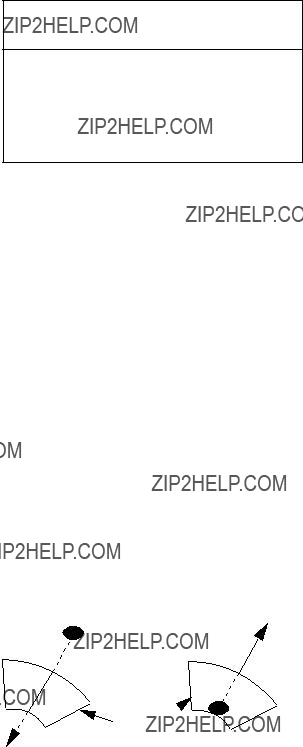
3.4 Bearing Resolution
Bearing resolution is a measure of the capability of a radar to display as separate targets the echoes received from two targets which are at the same range and are close together.
The principal factor which affects bearing resolution is horizontal beamwidth. Two targets at the same range must be separated by more than one beamwidth to appear as separate pips.

Horizontal beamwidth
Direction of scanner rotation
Target
Horizontal beamwidth
Direction of scanner rotation
Radar cannot display targets as separate echoes because they are within the beamwidth.
Figure
3.5 False Echoes
Occasionally false echoes appear on the screen at positions where there is no target. In some cases the effects can be reduced or eliminated. The operator should familiarize himself or herself with the appearance and effects of these false echoes, so as not to confuse them with echoes from legitimate contacts.
Multiple echoes
Multiple echoes occur when a short range, strong echo is received from a ship, bridge, or breakwater. A second, a third or more echoes may be observed on the display at double, triple or other multiples of the actual range of the target as shown in Figure
True echo
Figure
Every time the antenna rotates, some radiation escapes on each side of the
True echo

Spurious
target
Antenna
Figure

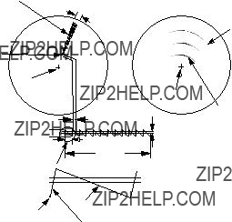
Indirect echoes
Indirect echoes may be returned from either a passing ship or returned from a reflecting surface on your own ship, for example, a stack. In both cases, the echo will return from a legitimate contact to the antenna by the same indirect path. The echo will appear on the same bearing of the reflected surface, but at the same range as the direct echo. Figure
Blind and shadow sectors
Funnels, stacks, masts, or derricks in the path of antenna may reduce the intensity of the radar beam. If the angle subtended at the antenna is more than a few degrees a blind sector may be produced. Within the blind sector small targets at close range may not be detected while larger targets at much greater ranges may be detected. See Figure
Indirect echoes may be recognized as follows:
Vessel taller than whart
 Wharf
Wharf
Wharf
Blind sector (no echo)
Mast, etc. in path of radar beam
Size of blind sector depends on target size and range.
marker
Figure
Figure
3.6 SART
Note: The SART (Search and Rescue Transponder) information below is excerpted from IMO SN/Circ 197 Operation of Marine Radar for SART Detection.
Position of
SART
Lines of 12 dots are displayed in concentric arcs.
Echo of
SART
A Search and Rescue Transponder (SART) may be triggered by any
When the range to the SART is reduced to about 1 nm, the radar display may show also the 12 responses generated during the fast sweeps. These additional dot responses, which also are equally spaced by 0.64 nm, will be interspersed with the original line of 12 dots. They will appear slightly weaker and smaller than the original dots.
Low speed sweep signal
Sweep start
High speed sweep signal
Figure
General procedure for detecting SART response
1.Use the range scale of 6 or 12 nm as the spacing between the SART responses is about 0.6 nm (1125 m) to distinguish the SART.
2.Turn off the automatic clutter suppression.
3.Turn off the Interference Rejector.
General remarks on receiving
SART
SART range errors
When responses from only the 12 low frequency sweeps are visible (when the SART is at a range greater than about 1 nm), the position at which the first dot is displayed may be as much as 0.64 nm beyond the true position of the SART. When the range closes so that the fast sweep responses are seen also, the first of these will be no more than 150 meters beyond the true position.
Radar bandwidth
This is normally matched to the radar pulselength and is usually switched with the range scale and the associated pulselength. Narrow bandwidths of
Any radar bandwidth of less than 5 MHz will attenuate the SART signal slightly, so it is preferable to use a medium bandwidth to ensure optimum detection of the SART.
Radar side lobes
As the SART is approached, sidelobes from the radar antenna may show the SART responses as a series of arcs or concentric rings. These can be removed by the use of the
GAIN
For maximum range SART detection the normal gain setting for long range detection should be used, that is, with background noise speckle visible.
STC control
For optimum range SART detection, this control should be set to the minimum. Care should be exercised as a wanted target in sea clutter may be obscured. Note also that in clutter conditions the first few dots of the SART response may not be detectable, irrespective of the setting of the
Some sets have automatic/manual anti- clutter sea control facilities in which case the operator should switch to manual.
FTC control
This should be used normally (to break up areas of rain) when trying to detect a SART response which, being a series of dots, is not affected by the action of the
Some sets have automatic/manual anti- clutter rain control facilities in which case the operator should switch to manual.
When the range to the SART is reduced to about 1 nm, the radar display may show also the 12 responses generated during the fast sweeps. These additional dot responses, which also are equally spaced by 0.64 nm, will be interspersed with the original line of 12 dots. They will appear slightly weaker and smaller than the original dots.

3.7 Racon (Radar Beacon)
A racon is a radar transponder which emits a characteristic signal when triggered by a ship???s radar (usually only the 3 centimeter band). The signal may be emitted on the same frequency as that of the triggering radar, in which case it is superimposed on the ship's radar display automatically.
The racon signal appears on the PPI as a radial line originating at a point just beyond the position of the radar beacon or as a Morse code signal (see figure below) displayed radially from just beyond the beacon.
Racon
Figure
4. MAINTENANCE &
TROUBLESHOOTING
This chapter tells you how to keep your radar in good working order. Before reviewing this chapter please read the safety information which follows.
 WARNING
Do not open the equipment.
Only qualified personnel should work inside the equipment.
RF RADIATION HAZARD
The radar antenna emits high frequency radio radiation which
can be harmful, particularly to your eyes. Never look directly into the antenna from a distance of less than 1 m when the radar is in operation as you could injure the cornea of your eyes. Always make sure the radar is set to
4.1 Preventative
Maintenance
Regular maintenance is important for good performance. Always keep the equipment as free as possible from dirt, dust, and water splashes. Make sure all screws securing the components are properly tightened.
A maintenance program should be established and should at least include the items listed in Table
Table

4.2 Replacing the Fuse
The fuse in the power cable protects the equipment against reverse polarity of ship???s mains, overcurrent, and equipment fault. If the fuse blows, find the cause before replacing it. Never use an incorrect fuse??? serious damage to equipment may result and void the warranty.
4.3 Troubleshooting
Table

4.4 Test
The self test facility checks the keyboard, ROM and RAM for proper operation. You may run the test as follows.
1.Press the [MENU] key.
2.Select Self Check. The following display appears.
M851
 SELF TEST
 KEY Board TEST : Press each key and note that the cor- responding key on the screen turns black.
Prog. No. 03591371**
ROM : OK
RAM : OK
On Hours 000008.3H
Tx Hours 000007.9H
<MENU> = MAIN MENU
**: Program version no.
Figure
3.To check the keyboard, press each key except the [MENU] key. Its corresponding location on the display lights in black if the key is operating properly.
4.To escape from the test, press the [MENU] key.
The ROM and RAM are automatically checked. If NG (No Good) appears to the right of ROM or RAM indication, contact your dealer for advice.
NMEA data can be displayed on the test screen as follows;
1.Press the [+] key. NMEA data appears on the upper half of the screen.
2.Press the [TONE] key to select input source; NAV, HDG or E/S.
3.To display the NMEA data over the entire screen, press the
4.To erase the NMEA data, press the [+] key.
4.5 Replacing the
Magnetron
When the magnetron has expired distant targets cannot be seen on the display. When you feel long range performance has decreased contact a FURUNO agent or dealer about replacement of the magnetron.
Magnetron type: MG5248 (Code No.
MENU TREE
5.Tuning (AUTO, MANUAL)
6.Self Check (Checks equiment for proper operation.)
7.Installation Setup 1 (For installation use.)
Default settings shown in bold italic.
SPECIFICATIONS OF MARINE RADAR
MODEL 851
SP - 1
SP - 2
SP - 3

INDEX
A
F
P
W
