
C
9 - 5 2 , A s h i h a r a - c h o , N i s h i n o m i y a , J a p a n
A l l r i g h t s r e s e r v e d .  Printed in Japan
P U B . N o . O M E - 3 4 8 1 0
 Y o u r L o c a l A g e n t / D e a l e r

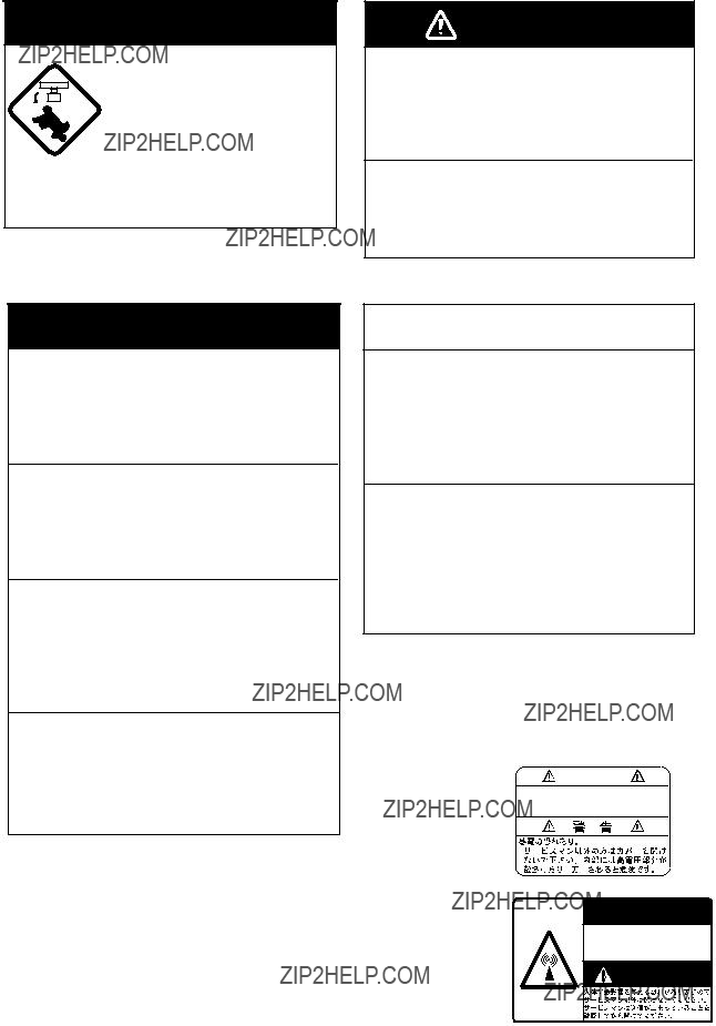
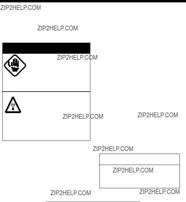
 SAFETY INSTRUCTIONS
 DANGER
Stay away from transmitting antenna.
The radar antenna emits microwave radiation which can be harmful to the human body, particularly the eyes. Never look directly into the antenna radiator from a distance of less than 1 m when the radar is in operation.
Radio Frequency Radiation Hazard
The radar antenna emits electromagnetic radio frequency (RF) energy which can be harmful, particularly to your eyes. Never look directly into the antenna aperture from a close distance while the radar is in operation or expose yourself to the transmitting antenna at a close distance.
Distances at which RF radiation levels of 100 and 10 W/m2 exist are given in the table below.
Note: If the antenna unit is installed at a close distance in front of the wheel house, your administration may require halt of transmission within a certain sector of antenna revolution. This is
i
 DANGER
Before turning on the radar make sure no one is near the scanner unit.
Prevent the potential risk of someone begin struck by the rotating antenna and exposure to RF radiation hazard.
WARNING
Use the proper fuse.
Fuse rating is shown in the chapter 5.
Use of a wrong fuse can result in equipment damage
Do not operate the equipment with wet hands.
Electrical shock can result.
 WARNING
Do not open the equipment.
Improper handling can result in electrical shock. Only qualified personnel shold work inside the equipment.
Do not disassemble or modify the equipment.
Fire electrical shock or serious injury can result.
Turn off the power immediately if water leaks into the equipment or the equip- ment is emitting smoke or fire.
Continued use of the equipment can cause fire or electrical shock.
Do not place
Fire or electrical shock can result if a liquid spills into the equipment.
 CAUTION
Do not use the equipment for other than its intended purpose.
Use of the equipment as a stepping stool, for example, can result in personal injury or equipment damage.
No one navigation device should ever be solely replied upon for the navigation of a vessel.
Always confirm position against all available aids to navigation, for safety of vessel and crew.
Two warning labels are attached to the display unit and scanner unit. Do not remove these labels. If labels are peeling off or are illegible, contact
a FURUNO agent or dealer.
<Scanner Unit>
Name: Radiation Warning Label
Type:
Code no.:

 WARNING
Radiation hazard. Only qualified personnel should work inside scanner. Confirm that TX has stopped before opening scanner.
ii

FOREWORD
Congratulations on your choice of the FURUNO MODEL 1761
For over 50 years FURUNO Electric Com- pany has enjoyed an enviable reputation for innovative and dependable marine electron- ics equipment. This dedication to excellence is furthered by our extensive global network of agents and dealers.
Your radar is designed and constructed to meet the rigorous demands of the marine en- vironment. However, no machine can per- form its intended function unless properly installed and maintained. Please carefully read and follow the recommended proce- dures for installation, operation and mainte- nance.
While this unit can be installed by the pur- chaser, any purchaser who has doubts about his or her technical abilities may wish to have the unit installed by a FURUNO representa- tive or other qualified technician. The impor- tance of a through installation can not be overemphasized.
We would appreciate hearing from you, the
Thank you for considering and purchasing FURUNO equipment.
Features
Your radar has a large variety of functions, all contained in a remarkably small cabinet.
The main features of the MODEL 1761
??Traditional FURUNO reliability and qual- ity in a compact, lightweight and
??Durable brushless antenna motor.
??
??Standard features include EBL (Electronic Bearing Line), VRM (Variable Range Marker), Guard Alarm, Display Off Cen- ter, and Echo Trail.
??Watchman feature periodically transmits the radar to check for radar targets which may be entering the alarm zone.
??Ship???s position in latitude and longitude, range and bearing to a waypoint, and ship???s speed/heading/course can be shown in the bottom text area. (Requires a navigation aid which can output such data in IEC 61162 format.)
??Zoom feature provided.
iii

TABLE OF CONTENTS
2.21 Adjusting Control Panel Brilliance ......
3. FALSE ECHOES
4. MAINTENANCE & TROUBLE-
SHOOTING
iv

MENU TREE
MENU KEY  1. ECHO STRETCH (ON, OFF)
2.I. REJECT (OFF, ON)
3.PANEL DIMMER (0, 1, 2, 3, 4)
4.PLOT INTVL (CONT, 30S, 1M, 3M, 6M)
5.PLOT BRILL (LOW, @HIGH)
6.RANGE (NM) set with (RING)
(1/4, 1/2, 3/4, 1, 1.5, 2, 3, 4, 6, 8, 12, 16, 24, 48)
7.WATCHMAN (OFF, 5M, 10M, 20M)
8.NAV DATA (ON, OFF)
9.EBL/+CURSOR (TRUE, REL)
v

TABLE OF CONTENTS BY
INDICATION, MARKER
vi
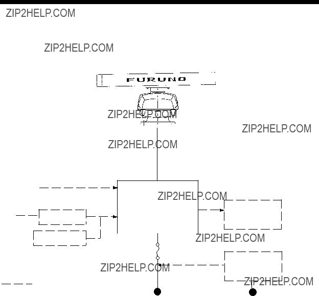
SYSTEM CONFIGURATION
Scanner Unit
Navigation IEC 61162* (In/Out) device 
vii

1. PRINCIPLE OF OPERATION
1.1 What is Radar?
The term ???RADAR??? is an acronym meaning RAdio Detection And Ranging. Although the basic principles of radar were developed dur- ing World War II, echoes as an aid to naviga- tion is not a new development.
1.2How Ships Determined Position Before Radar
Before the invention of radar, when running in fog near a rugged shoreline, ships would sound a short blast on their whistles, fire a shot, or strike a bell. The time between the origination of the sound and the returning of the echo indicated how far the ship was from the cliffs or the shore. The direction from which the echo was heard indicated the rela- tive bearing of the shore.
1.3How Radar Determines Range
Radar determines the distance to the target by calculating the time difference between the transmission of a radar signal and the recep- tion of the reflected echo. It is a known fact that radar waves travel at a nearly constant speed of 162,000 nautical miles per second. Therefore the time required for a transmitted signal to travel to the target and return as an echo to the source is a measure of the dis- tance to the target. Note that the echo makes a complete round trip, but only half the time of travel is needed to determine the
1.4How Radar Determines Bearing
The bearing to a target found by the radar is determined by the direction in which the ra- dar scanner antenna is pointing when it emits an electronic pulse and then receives a re- turning echo. Each time the scanner rotates pulses are transmitted in the full 360 degree circle, each pulse at a slightly different bear- ing from the previous one. Therefore, if one knows the direction in which the signal is sent out, one knows the direction from which the echo must return.
1.5Radar Wave Speed and Scanner Rotation Speed
Note that the speed of the radar waves out to the target and back again as echoes is extremely fast compared to the speed of ro- tation of the scanner. By the time radar ech- oes have returned to the scanner, the amount of scanner rotation after initial transmission of the radar pulse is extremely small.
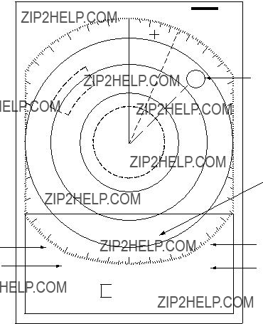
1.6 The Radar Display
The range and bearing of a target is displayed on what is called a Plan Position Indicator (PPI). This display is essentially a polar dia- gram, with the transmitting ship???s position at the center. Images of target echoes are re- ceived and displayed at their relative bear- ings, and at their distance from the PPI center.
With a continuous display of the images of targets, the motion of the transmitting ship is also displayed.
A
Targets
 DA
DA
Heading marker
Range and bearing of a target, relative to own ship, are readable on the PPI.
D
B
CB
C
Figure

2. OPERATION
2.1 Control Description
Turns power on.
Press together with [STBY/TX] key to turn power off.
Alternates between
Lights (in green) to show the radar is in the "echonomy
Adjusts the brightness of the screen.
Selects radar range.
The "+" and
RANGE
(Control) Adjusts sensitivity of radar receiver.
(Switch) 1. Temporarily erases heading marker.
2.Change + cursor data from R/B to L/L and vice versa.
(Control) Reduces sea clutter caused by waves.
(Switch) Turns on/off the radar target plotting
(Control) Reduces rain clutters. (Switch) Suppresses heavy
precipitation.
Shifts the display; turns the zoom  function on, and restores normal picture, in that order.
Turns the Electronic Bearing
Line (EBL) on and off.
Turns on and off the guard zone alarm.
SHIFT
ZOOM
EBL
 GUARD
GUARD
RING  Turns the fixed range rings on and off.
VRM  Turns the Variable Range Marker
(VRM) on and off.
MENU
Turns the menu display on and off.
 Trackball
(1)Shifts cursor, EBL and VRM.
(2)Sets guard zone.
(3)Selects items and options on menu.
(4)Shifts origin of EBL and VRM.
Figure
2.2 Turning the Radar On/Off
After confirming there are no crew near the scanner unit, press the [POWER] key to turn on the power.
The front panel will light up. The magnetron takes about two minutes and thirty seconds to warm up before the radar can be oper- ated. The time remaining for warm up of the magnetron appears at the center of the dis- play, counting down from 2:29 to 0:01.
To turn off the radar, press the [POWER] and [TX] key together.
2.3 Transmitting
After the power is turned on and the magne- tron has warmed up, the message
2.4
When you won???t be using the radar for an extended period, but you want to keep it in a state of readiness, place it in
Economy mode
The CRT can be set to automatically turn it- self off when in
2.5Selecting the Range
The range selected automatically determines the fixed range ring interval, the number of fixed range rings, pulselength, and pulse rep- etition rate, for optimal detection in short to long ranges. The range and ring interval ap- pear at the top left corner of the display.
Selecting the range
Press the [- RANGE +] key. The range and range ring interval appear at the top left cor- ner on the display.
Tips for selecting the range
???When navigating in or around crowded harbors, select a short range to watch for possible collision situation.
???If you select a lower range while on open water, increase the range occasionally to watch for vessels that may be heading your way.
2.6Adjusting Picture Brilliance
The [BRILL] key adjusts the brilliance of the radar picture in eight levels.
Press the [BRILL] key to set the brilliance level.
2.7Adjusting Receiver Sensitivity
The [GAIN] control adjusts the sensitivity of the receiver. It works in precisely the same manner as the volume control of a broadcast receiver, amplifying the signals received.
The proper setting is such that the back- ground noise is just visible on the screen. If you set up noise is just visible on the screen. If you set up for too little sensitivity, weak echoes may be missed. On the other hand excessive sensitivity yields too much back- ground noise; strong targets may be missed because of the poor contrast between desired
echoes and the background noise on the dis- play.
To adjust receiver sensitivity, transmit on long range, and adjust the [GAIN] control so back- ground noise is just visible on the screen.
Tips on adjusting GAIN
???In certain circumstances it may be useful to reduce the gain slightly to improve range resolution, clear up the picture, or reduce clutter caused by rain or snow.
???Range resolution is a measure of the ca- pability of a radar to display as separate pips the echoes received from two targets which are on the same bearing, and are close together radially. With reduction in the gain setting, the echoes may be made to appear as separate pips on the display.
???When sailing or cruising in crowded re- gions a slight reduction in gain often helps to clear up the picture. This should be done carefully, otherwise weak targets may be missed.
???Echoes from ships inside a squall or storm may be obscured if the gain is at its nor- mal setting, since the clutter may have masked, but not completely, echoes from the targets.
Note: In all cases, return the gain to its origi- nal position after any temporary reduction is no longer required.
How the A/C SEA control works
The [A/C SEA] control reduces the amplifi- cation of echoes at short ranges (where clut- ter is the greatest) and progressively increases amplification as the range in- creases, so amplification will be normal at those ranges where there is no sea clutter.
Adjusting the A/C SEA control
The proper setting of the A/C SEA should be such that the clutter is broken up into small dots, and small targets become distinguish- able.
If the control is set too low, targets will be hidden in the clutter, while if it is set too high, both sea clutter and targets will disappear from the display. In most cases adjust the control until clutter has disappeared to lee- ward, but a little is still visible windward.
1.Confirm that the sensitivity is properly ad- justed, and then transmit on short range.
2.Adjust the [A/C SEA] control so small tar- gets are distinguishable but some clutter remains on the display.
2.8Adjusting the A/C SEA Control
(reducing sea clutter)
Echoes from waves can be troublesome, cov- ering the central part of the display with ran- dom signals known as ???sea clutter???. The higher the waves, and the higher the antenna above the water, the further the clutter will extend. Sea clutter appears on the display as many small echoes which might affect radar performance. (See the
Figure
Tip for adjusting the A/C SEA
A common mistake is to

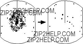
2.9Adjusting the A/C RAIN Control
(reducing rain clutter)
The vertical beamwidth of the antenna is de- signed to see surface targets even when the ship is rolling. However, by this design the unit will also detect rain clutter (rain, snow, hail, etc.) in the same manner as normal tar- gets. Figure
Adjusting A/C RAIN
When rain clutter masks echoes, adjust the [A/C RAIN] control. This control splits up these unwanted echoes into a speckled pat- tern, marking recognition of solid targets easier.
Figure
Note: In addition to reducing clutter, the [A/C RAIN] control can be used in fine weather to clarify the picture when navigating in confined waters. However, with the circuit activated the receiver is less sensitive. Therefore, turn off the circuit when its function is not required.
2.10 Adjusting FTC
To suppress rain clutter from heavy storms or scattered rain clutter, press the [A/C RAIN] control ([FTC] switch). The FTC circuit splits up these unwanted echoes into a speckled pattern, marking recognition of solid targets easier. ???FTC??? appears at the top
Note: In addition to reducing clutter, the FTC can be used in fine weather to clarify the pic- ture when navigating in confined waters. However, with the circuit activated the re- ceiver is less sensitive. Therefore, turn off the circuit when its function is not required.
2.11 Tuning the Radar Receiver
The radar receiver is tuned automatically each time you turn on the power, thus there is no front panel control for adjustment of the receiver. To show the automatic tuning cir- cuit is working, a tuning bar displays tuning condition.
2.12Erasing the Heading Marker
The heading marker may occasionally mask a target. To view the target, you can tempo- rarily erase the heading marker by pressing and holding down the [GAIN (HM OFF)] con- trol. Release the control to
 Heading
marker
Figure

2.13Select the Cursor Data Display
When connecting with NAV (IEC61162 for- mat) and gyro converter (IEC61162 or AD- 10 format), this radar can show the cursor position by Latitude/longitude at bottom of screen.
Each time pressing [HM OFF] key, the data will change from Range/Bearing to Latitude/ longitude and vice versa.
When the cursor position is displayed by Lati- tude/Longitude, pressing the [HM OFF] key outputs L/L data of the cursor position (TLL) to the plotter. Then Range/Bearing are dis- played instead of L/L.
2.14Turning the Range Ring On/Off
When range rings obscures a target, you can erase them by pressing the [RING] key.
2.15 Measuring the Range
You can measure the range to a target three ways: by the range rings, by the cursor, and by the VRM (Variable Range Marker).
Measuring range by range rings
Count the number of rings between the cen- ter of the display and the target. Check the range ring interval and judge the distance of the echo from the inner edge of the nearest ring.
To turn the rings on or off, press the [RING] key.
Measuring range by cursor
Operator the trackball to place the cursor in- tersection on the inside edge of the target echo. The range to the target, as well as the bearing, appears at the bottom of the display.
Measuring by VRM
1.Press the [VRM] key to display a VRM. (The VRM is the dotted ring.)
2.Place the VRM on the inside edge of the target by operating the trackball.
3.Press the [VRM] key again to fix the VRM to the position.
4.Check the range readout to find the range to the target. To erase the VRM, press and hold down the [VRM] key for about three seconds.
Range
 6.0 NM Range ring
  2.0
2.0
interval
Cursor
Figure
Unit of range measurement
You can display the range readouts of the VRM and the cursor in nautical miles or kilo- meters. This is done at installation.
2.16 Measuring the Bearing
There are two ways to measure the bearing to a target: by the cursor, and by the EBL (Electronic Bearing Range).
Measuring bearing by cursor
Operate the trackball to bisect the target with the cursor intersection. The bearing to the target appears at the bottom of the display.
Measuring by EBL
1.Press the [EBL] key to display an EBL. (The EBL is the dotted line.)

2.Position the EBL so it bisects the target by operating the trackball.
3.Press the [EBL] key again to fix the EBL to the position.
4.Check the bearing readout to find the bearing of the target. To erase the EBL, press and hold down the [EBL] key for about three seconds.
MAG (or GYRO) BEARING*
6.0 NM MAG115.0??
2.0
Target
 Cursor
 EBL
EBL
???Bearings of stationary or slower moving targets are more accurate than bearings of faster moving targets.
???To minimize bearing errors keep echoes in the outer half of the picture by chang- ing the range scale; angular difference becomes difficult to resolve as a target approaches the center of the display.
2.17Shifting and Zooming the Display
The [SHIFT/ZOOM] key has two functions: display shifting and display zoom. Each time the key is pressed the function changes in the following sequence.
 Normal
  Shift
Shift  Zoom
Zoom
Figure
Shift
Figure
The bearing measured by the cursor or the EBL can be displayed in relative or true bear- ings (heading sensor or gyrocompass con- nection required). Relative bearings are relative to the bow of the vessel, and true bearings are relative to the True North. The indication ???MAG??? (or GYRO???) and the head- ing sensor (or gyrocompass) bearing (your ship???s bearing) appear at the top of the screen.
Note that the bearing to the cursor always varies with trackball operation. The EBL and its indication, however, are automatically fixed when the [EBL] key is pressed or 10 seconds elapses without trackball operation.
Tips on measuring bearing
???Bearing measurements of smaller targets pips are more accurate; the center of larger target pips is not as easily identi- fied.
The own ship???s position can be shifted to any position within the current range. The primary advantage of the shifted display is that for any range setting, the view ahead of your own ship can be extended without changing the range.
Place the cursor on area you wish to shift to the screen center and then press the [SHIFT/ ZOOM] key. The indication ???SHIFT??? appears. To restore normal operation press the key twice.
Note: If the cursor is not within the current range when the key is pressed, an audible beep sounds and the outermost range ring blinks twice , even if the range rings are off.
Zoom
The zoom feature allows you to double the area between own ship and an arbitrary lo- cation, to take a closer look at an area of in- terest without changing the range.
1.Operate the trackball to place the cursor on the target you want or area you want to zoom.
2.Press the [SHIFT/ZOOM] key. The indi- cation ???ZOOM??? appears and brinks.
3.To turn off the zoom, press the [SHIFT/ ZOOM] key again, or change the range.
(Normal display)
Place cursor where desired.
Cursor
2.18 Menu Operation
The menu, consisting of 9 items, mostly con- tains
Note: Current selections shown in reverse video.
Press the [SHIFT/ZOOM] key.
Press the [SHIFT/ZOOM] key.
Press the [SHIFT/ZOOM] key.
Figure

2.19 Echo Stretch
Normally, the reflected echoes from long dis- tance targets appear on the screen as weaker and smaller blips even through they are com- pensated by the radar???s internal circuitry. The Echo Stretch function magnifies these small blips.
1.Press the [MENU] key to open the menu.
2.Operate the trackball to select ???1. ECHO STRETCH???.
3.Press the [RANGE] key to select ???ON???.
The indication ???ES??? appears at the upper
To turn off the echo stretch, select ???OFF??? on the MENU display.
Note 1: This function magnifies not only tar- gets but also sea clutter and radar interfer- ence are properly adjusted before activating the echo stretch.
Note 2: This function is inactivate on short ranges, that is 0.25 to 1 nautical miles. ???ES??? appears in reverse video when the echo stretch is turned on in those ranges.
2.20Suppressing Radar Interference
Radar interference may occur when near an- other shipborne radar operating in the same frequency band as your radar. Its
Figure
1.Press the [MENU] key to open the menu.
2.Operate the trackball to select ???2. I. RE- JECT???.
3.Press the [RANGE] key to select ???ON???. (Factory setting is ON.)
The indication ???IR??? appears at the upper right- hand side of the screen. Press the [MENU] key again to erase the menu display.
2.21Adjusting Control Panel Brilliance
Adjusts the backlighting of the front panel in five steps.
1.Press the [MENU] key to open the menu.
2.Operate the trackball to select ???3. PANEL DIMMER???.
3.Press the [RANGE] key to select level de- sired.
4.Press the [MENU] key again to erase the menu.
2.22 Selecting Ranges
This radar has 14 ranges, some which you may not require. You can select or deselect ranges as follows.
1.Press the [MENU] key to open the menu.
2.Operate the trackball to select ???6. RANGE???.
3.Press the [RANGE] key to place the un- derline under the range you want to se- lect or deselect.
4.Press the [RING] key to select or dese- lect.
5.Repeat step 4 and 5.
Maximum number of ranges is all ranges. Minimum number of ranges is two.
2.23EBL/Cursor Bearing Reference
EBL and cursor bearing can be displayed relative to own ship???s heading (Relative) or with reference to North (True).
Note: Magnetic compass or gyrocompass connection required for true bearing.
1.Press the [MENU] key to open the menu.
2.Operate the trackball to select ???9. EBL/ +CURSOR???
3.Press the [RANGE] key to select ???TRUE??? or ???REL (Relative)???.
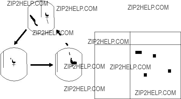
2.24 Guard Alarm
The alarm allows the operator to set the de- sired range (0 to maximum range) and bear- ing (0 to 360 degrees) for a guard zone, called Auto In/Out alarm. When ships, islands, land- masses, etc. go into (or go out of) the guard zone an audible alarm sounds to call the operator???s attention.
Before setting the alarm, be sure the [GAIN] control is properly adjusted, because the au- dible alarm sounds when the fifth or more level quantization echoes go into or go out of the guard zone.
1.Mentally create the guard zone you want to display
2.Set upper (lower) left edge of the guard zone with the cursor, and press the [GUARD] key.
The indication ???*GUARD??? (asterisk blink- ing) appears at the upper
3.Moving the trackball clockwise, set the lower (upper) right edge of the guard zone. The guard zone now appears on the display and alarm function has been actuated, See Figure
Note: To create a 360 degree guard zone, rotate the cursor counterclockwise instead of clockwise.
4.Press the [GUARD] key again. The as- terisk disappears and the alarm function is actuated after three to five antenna scannings, and then, the indication ???GUARD??? is replaced by ???G(IN)??? or ???G(OUT)???.
5.Any ships, landmasses, etc. coming into or going out of the guard zone will trigger the audible alarm. If the audible alarm sounds you can silence it by pressing the [GUARD] key. When this is done the indi- cation ???GUARD??? appears in reverse video.
6.Press the [GUARD] key again to restore the audible alarm. ???GUARD??? lights in nor- mal video.
7.To cancel both the guard zone and the audible alarm, press and hold down the [GUARD] key for three seconds.
Note 1: When the range is less than the half of the guard zone range, the guard zone dis- appears from the screen and ???UP RANGE??? indication appears. If this happens, select a range which will again display the guard zone on the screen.
Note 2: A target echo does not always mean a landmass, reef, ships or surface objects but can imply returns from sea surface or pre- cipitation. As the level of these returns varies with environment, the operator should (prop- erly) adjust the A/C SEA, A/C RAIN, FTC and GAIN to be sure target echoes within the guard zone are not overlooked by the alarm system.
Note: The audible alarm does not sound for the target originally existing the zone.
Case 2: When no targets exist inside the zone, the alarm zone is automatically set to ???Auto In Alarm??? mode and the indication ???GUARD??? is replaced by ???G (IN)???. The au- dible alarm sounds only on targets which go into the zone. See Figure
Asterisk blinking
Dashed line: no alarm
Guard  zone
zone
Figure
Guard zone
Figure
2.25Watchman
The watchman function turns on the radar and transmits its for about 30 seconds at a predetermined interval to check for targets
Cin a guard zone. This feature is useful when you do not need the radar???s function continu- ously but want to be alerted to radar targets in an area.
When the watchman feature is on, an inter- nal timer turns on the radar every 5, 10 or 20 minutes and the radar transmits for 30 sec- onds to check for the existence of radar tar- gets in a guard zone.
Auto In/Out Alarm
When the guard zone is set completely, the radar starts searching for targets inside the guard zone for 8 to 12 seconds. The indica- tion ???GUARD??? appears during this period.
Case 1: When there are targets inside the zone, the alarm zone is automatically set to ???Auto Out Alarm??? mode and the indication ???GUARD??? is replaced by ???G (OUT)???. The au- dible alarm sounds only on targets which go out of the zone or disappear. See Figure 2- 13 (1).
Watchman starts.
Figure

1.Determine the guard zone (usually 360 degrees) with the guard alarm function.
2.Press the [MENU] key to open the menu.
3.Operate the trackball to select ???7. WATCHMAN??? .
4.Press the [RANGE] key to select a trans- mission interval.
5.Press the [MENU] key to actuate the watchman mode. The indication ???WATCH- MAN??? appears and the radar transmits for one minute and then turns to
Note: The antenna radiator does not rotate in the ???ECHONOMY???
6.The radar automatically starts transmit- ting after the time selected at step 4 has passed. It transmits for one minute ap- proximately and examines the guard zone for change.
(a)If the condition is unchanged, the ra- dar automatically returns to
(b)If the condition differs from the previ- ous one, the radar sounds an audible alarm, cancels the watchman mode and transmits continuously.
7.To cancel the watchman mode manually, press any key.
2.26 Plotting
This function plots the movement of other ships relative to your own ship.
Press the [PLOT (A/C RAIN)] control to start plotting. The indication ???PLOT??? and a timer appear at the top
val (except for 15 seconds) appears to the right of the indication PLOT.
If the range is changed during plotting, plot- ting begins anew with the newly selected range. To cancel plotting, press the [PLOT] key.
Plotting Interval
(30 sec., 1min.,3min., 6min.)
Timer
Figure
Plot Brilliance
The brilliance of plotted echoes is selectable through the MENU display. Press the [MENU] key and select ???5. PLOT BRILLIANCE???.
2.27 Navigation Data Display
Navigation data can be displayed on the screen if your radar receives navigation in- put form a
To return the navigation data display on or off, press the [MENU] key and select ???8. NAV DATA???.
To display TDs instead of L/L, press the [GAIN] control. Press the control again to restore L/L.
If the output format is FURUNO CIF a jumper wire must be connected to ???JUP1??? on the SPU Board in the display unit. Note that for CIF format the bearing measurement method (Magnetic or True) does not appear for bear- ing to waypoint data.
Figure

3. FALSE ECHOES
Occasionally false echoes appear on the screen at positions where there is no target. In some cases the effects can be reduced or eliminated. The operator should familiarize himself or herself with the appearance and effects of these false echoes, so as not to confuse them with echoes from legitimate contacts.
3.1 Multiple Echoes
Multiple echoes occur when a short range, strong echo is received from a ship, bridge,
3.2
Every time the scanner rotates, some radia- tion escapes on each side of the beam??? called
or breakwater. A second, a third or more ech- oes may be observed on the display at double, triple or other multiples of the actual range of the target as shown in Figure
True echo
Multiple reflection echoes can be reduced and often removed by decreasing the sensi- tivity or properly adjusting the A/C SEA.
True echo
Own ship  Multiple
echo
Figure
 Side-lobe
Sprious target
Antenna
Figure

3.3 Indirect Echoes
Indirect echoes may be returned from either a passing ship or returned from a reflecting surface on your own ship, for example, a stack. In both cases, the echo will return from a legitimate contact to the scanner by the same indirect path. The echo will appear on the same bearing of the reflected surface, but at the same range as the direct echo. Figure
???they usually occur in a shadow sector
???they appear on the bearing of the obstruc- tion but at the range of the legitimate con- tact
???when plotted, their movements are usu- ally abnormal, and
???their shapes may indicate they are not di- rect echoes.
True  echo
echo
Bridge
 Indirect
Indirectecho echo
Figure
3.4 Blind and Shadow Sectors
Funnels, stacks, masts, or derricks in the path of antenna may reduce the intensity of the radar beam. If the angle subtended at the antenna is more than a few degrees a blind sector may be produced. Within the blind sector small targets at close range may not be detected while larger targets at much greater ranges may be detected. See Figure
Figure
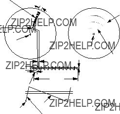
3.5SART (Search and Rescue Transponder)
A Search and Rescue Transponder (SART) may be triggered by any
When the range to the SART is reduced to about 1 nm, the radar display may show also the 12 responses generated during the fast sweeps. These additional dot responses, which also are equally spaced by 0.64 nm, will be interspersed with the original line of 12 dots. They will appear slightly weaker and smaller than the original dots.
Position of
SART
Low speed sweep signal
Sweep start
High speed sweep signal
Figure
Showing SART marks on the radar display
To show the SART marks only on the radar display, detune the radar receiver manually. This erases or weakens all normal radar ech- oes, but, the SART marks are not erased be- cause the SART response signal scans over all frequencies in the 9 GHz band. When the radar approaches the SART in operation, the SART marks will enlarge to large arcs, blur- ring a large part of the screen. Reduce the sensitivity and adjust the sea clutter control of the radar.
Summary to detect SART response
1.Use range scale of 6 or 12 nm as the spacing between the SART responses is about 0.6 nm (1125 m) to distinguish the SART.
2.Turn off the automatic clutter suppression.
3.Turn off the Interference Rejector.
General remarks on receiving SART
Radar range scale
When looking for a SART it is preferable to use either the 6 or 12 nautical mile range scale. This is because the total displayed length of the SART response of 12 (or 24) dots may extend approximately 9.5 nautical miles beyond the position of the SART and it is necessary to see a number of response dots to distinguish the SART from other re- sponses.
SART range errors
When responses from only the 12 low fre- quency sweeps are visible (when the SART is at a range greater than about 1 nm), the position at which the first dot is displayed may be as mush as 0.64 nm beyond the true po- sition of the SART. When the range closes so that the fast sweep responses are seen also, the first of these will be no more than 150 meters beyond the true position.
4. MAINTENANCE & TROUBLESHOOTING
This chapter tells you how to keep your ra- dar in good working order. Before reviewing this chapter please read the safety informa- tion which follows.
 DANGER
Turn off the power before performing any maintenance or troubleshooting procedure.
Hazardous voltages can shock, burn or cause death. Only qualified personnel totally famillier with electrical circuits should work inside the units.
RF RADIATION HAZARD
The radar scanner emits high frequency
radio radiation which can be harmful, particularly to your eyes.
Never look directly into the scanner from a distance of less than two feet when the radar is in operation as you could injure the cornea of your eyes. Always make sure the radar is set to
4.1 Preventive Maintenance
Regular maintenance is important for good performance. Always keep the equipment as free as possible from dirt, dust, and water splashes. Make sure all screws securing the components are properly tightened.
A maintenance program should be estab- lished and should at least include the items listed in Table
4.2 Replacing the Fuse
The fuse on the rear panel of the display pro- tects the equipment against reverse polarity of ship's mains, overcurrent, and equipment fault. If the fuse blows, find the cause before replacing it. Never use an incorrect fuse - serious damage to the equipment may re- sult and void the warranty.
12V: 10A fuse
24/32V: 5A fuse
 CAUTION
Use the proper fuse.
Use of a wrong fuse can result in equipment damage.
Table

4.3 Troubleshooting
Table
Table

4.4Life Expectancy of Magnetron
The following table shows the life expectancy of the magnetrons.
Table
SPECIFICATIONS OF MARINE RADAR
MODEL 1761
1. GENERAL
2. ANTENNA UNIT
3. TRANSCEIVER MODULE
4. DISPLAY UNIT
5. ENVIRONMENTAL CONDITION
6. POWER SUPPLY & POWER CONSUMPTION
7. COATING COLOR
8. COMPASS SAFE DISTANCE
Index
A
S