NAVIGATIONAL ECHO SOUNDER
NAVIGATIONAL ECHO SOUNDER

Nishinomiya
Pub. No.
( YOSH )
Your Local Agent/Dealer
FIRST EDITION : JAN. 2000
Q : DEC. 15, 2004
*00080890804*
*00080890804*
* 0 0 0 8 0 8 9 0 8 0 4 *
*OME23660Q00*
*OME23660Q00*
* O M E 2 3 6 6 0 Q 0 0 *


 SAFETY INSTRUCTIONS
 WARNING
ELECTRICAL SHOCK HAZARD
Do not open the equipment.
Only qualified personnel should work inside the equipment.
Immediately turn off the power at the switchboard if water leaks into the equipment.
Continued use of the equipment can cause fire or electrical shock. Contact a FURUNO agent for service.
Do not disassemble or modify the equipment.
Fire, electrical shock or serious injury can result.
Immediately turn off the power at the switchboard if the equipment is emitting smoke or fire.
Continued use of the equipment can cause fire or electrical shock. Contact a FURUNO agent for service.
Make sure no rain or water splash leaks into the equipment.
Fire or electrical shock can result if water leaks in the equipment.
Use the proper fuse.
Use of a wrong fuse can result in equipment damage and void the warranty.
 CAUTION
Do not power the equipment when the transducer is in air.
The transducer may become damaged.
WARNING LABEL
A warning label is attached to the equip- ment. Do not remove the label. If the label is missing or illegible, contact
a FURUNO agent or dealer.
 About the TFT LCD
The TFT LCD is constructed using the latest LCD techniques, and displays 99.99% of its pixels. The remaining 0.01% of the pixels may drop out or blink, how- ever this is not an indication of malfunc- tion.
i
RECORD OF MODIFICATIONS IN THIS OPERATOR???S MANUAL
ii

CONTENTS
Declaration of Conformity
iii

FOREWORD
A Word to
Thank you for purchasing this navigational echo sounder. We are confident you will discover why FURUNO has become synonymous with quality and reliability.
Dedicated in the design and manufacture of marine electronics equipment for half a century, FURUNO Electric Company has gained an unrivaled reputation as a world leader in the industry. This is the result of our technical excellence as well as our worldwide distribution and service network.
Please carefully read and follow the safety information and operating and maintenance instructions set forth in this manual before attempting to operate the equipment and conduct any maintenance. Your navigational echo sounder will perform to the utmost of its ability only if it is operated and maintained in accordance with the correct procedures.
This equipment is designed, produced and documented by FURUNO ELECTRIC CO., LTD., complying with ISO 9001 standards as certified by the Lloyd??s Register of Quality Assurance System.
Features
The FURUNO
The main features of the
1.Complies with the IMO and ISO standards
MSC.74(69) Annex 4 and ISO9875.
2.
3.
4.Wide variety of modes with
5.Automatic function permits unattended adjustment of range, gain, and pulselength. The range scale and gain automatically change to display the bottom.
6.Position, course, speed, time are repeated from the external devices.
7.Alarms: shallow water, bottom lost, power drop
iv

SYSTEM CONFIGURATION
DISPLAY UNIT
TRANSDUCER SWITCH BOX
MATCHING BOX
TRANSDUCER
: Standard Supply
: Optional Supply
: Local Supply
PRINCIPLE OF OPERATION
The
The transducers have a specific beam width with respect to their working frequency, 50 kHz or 200 kHz. The high frequency has a narrow beamwidth and is immune to aeration when the ship is going astern or in rough weather. The low frequency has a wide beamwidth and more powerful sounding capability.
v
SPECIFICATIONS OF NAVIGATIONAL ECHO SOUNDER
1.4Basic Display Range
1.8Pulse Repetition Rate (PRR)
7.5Category of Equipment Units
8.2Distribution Box/ Matching Box
2.5GY5/1.5
1OPERATION
1.1 Control Description
All operation of the
???
??? 


??? 


1
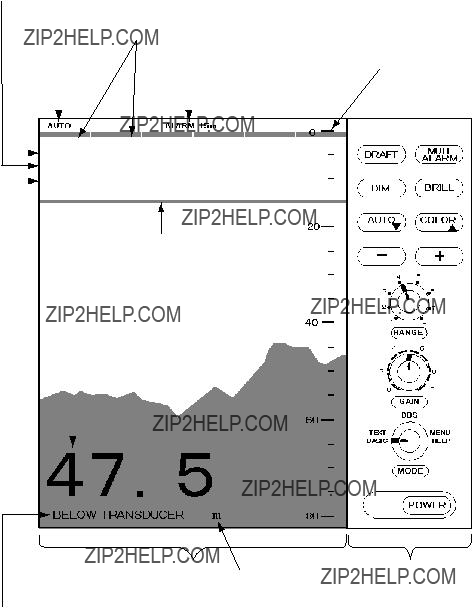
1.2 Indications, Markers
Depth alarm line
Explanation of depth (Below transducer, or below surface)
2
1.Turning on: Press the POWER Switch.
ROM: OK
DRAM: OK
SRAM: OK
BATTERY: OK
PROGRAM NO. 0252297002
2.Select a mode with the MODE Selector. The NAV position of the selector is recommended for general use. Display color is amber by default but may be customized. The unit of measurement is meters. You can freely select another mode at any time.
3.Turning off: Press the POWER Switch again.
Wait at least 5 s before reapplying the power.
Note: When two transducers are installed, make sure which transducer is used.
Note: When lat/long data input error occurs, ???EPFS??? ERROR appears on the screen. (EPFS: Electronic
Note: Tone or brilliance must be adjusted within 10 seconds after pressing the BRILL key. Otherwise the tone and brilliance window will be erased.
1.5 Panel Dimmer
1.Press the DIM key. The panel dimmer setting window appears.
LOW - + HIGH
DIMMER: 5 ?? ?? ?? ?? ??
2.Press the [+] or
3
1.6 Display Mode
The Mode Selector choose the display mode among NAV, DBS (depth below surface), HISTORY, LOGBOOK, OS DATA, HELP, and MENU.
 CAUTION
DBS is not a water clearance below keel.
Do not use this mode in shallow waters to avoid grounding.
1.6.1NAV mode
The depth from the transducer to the seabed (bottom clearance) is shown on the screen. Note ???BELOW TRANSDUCER??? appears at the bottom of the screen in this mode.
Shallow depth alarm: 20 m
NOTE: These parameters can be customized to your preference and the last setting is used at a next
1.6.2DBS mode
The Depth Below Surface mode provides a
When the DBS mode is selected, the message ???Confirm and set ship???s draft to use DBS mode??? appears. Confirm ship's draft and set it by referring to section 1.12.
BELOW KEEL (when the draft setting is
1.6.3HISTORY mode
This mode provides a mix of Contour and Strata displays. The Contour display can be scrolled over the past 24 h while the right side Strata display (layers of different colors according to reverberation strengths) shows the latest sounding for 5 minutes.
Pressing the [+] or
HISTORY
History of the bottom
If the range scale for both the Contour and Strata display must be the same. If they are not, the message ???OUT OF RANGE??? appears.
The update of the contour data may take max. one minute. Wait for one minute to display accurate contour if you change the range scale.
4
1.6.4LOGBOOK mode
The LOGBOOK shows time, depth and own ship position in tabular form in a
There are 60 pages and the total memory capacity is 720 points. Page 60/60 is the latest data and 1/60 is the oldest data. Pressing
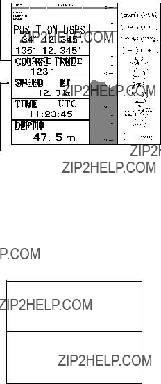
1.6.5OS DATA mode
This display mode indicates own ship position,
TRUE(true course) or
MAG (magnetic course) appears.
OS DATA
N
E
BT means Bottom track
There are two kinds of OS DATA displays: DATA 1 and DATA 2, as selected on the system menu. DATA 1 is the default setting, and it is shown in the figure above.
The DATA 2 display is as below.
TIME UTC
11:23:45
DEPTH
172 m
Note: When lat/long data input error occurs in the DATA 1 mode, ??EPFS?? ERROR appears on the screen. (EPFS: Electronic
5

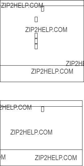
Enlarging data of interest
You can enlarge one of the data indications as follows:
1.Press the [???] or [???] key to select the data you want to enlarge. Current section is circumscribed with the blue cursor. For example, select the depth cell.
2.Press the [+] key.
DEPTH
172m
3.To return to the original display, press the
1.6.7MENU display
The menu provides functions which normally do not require frequent adjustment. For details see Chapter 2.
CLUTTER
1.6.6HELP display
This mode provides information about keys. Press desired key to obtain the corresponding information. The example below shows help information for MUTE ALARM.
HELP MENU
MUTE
DRAFT ALARM
DIM BRILL
AUTO COLOR
-
 +
+
PRESS KEY.
MUTE ALARM
To set or acknowledge alarms:
1.Press MUTE ALARM key.
2.Press
3.Press MUTE ALARM key to silence
the alarm.
PRESS KEY.
Press the [???] key, and the following appears.
CAUTION!
SYSTEM MENU IS ONLY
FOR INSTALLATION. DO
NOT CHANGE SETTINGS.
GO TO SYSTEM MENU?
NO YES
2/2
???: To select item - +: To set option
6
1.7 Range Scale
If the depth goes out of the correct display area, increase or decrease the range until the seabed appears near the center of the screen.
Adjust the Range Control, and current range selection is shown in the range display window.
In the AUTO mode, the range scale is automatically adjusted. See section 1.9 for details.
1.8 Gain Control
The GAIN Control adjusts the sensitivity of the receiver. The AUTO mode provides automatic adjustment and you are normally not required to adjust it. Current setting is shown at the upper
GAIN 5.5
Adjust the GAIN Control so that a slight amount of noise remains on the screen. Generally, use a higher gain setting for greater depths and a lower setting for shallower waters. Adjusting range is between 0.0 and 10.0 in 0.5 steps.
1.9 Automatic Operation
The automatic function automatically selects the proper gain, range scale and clutter level according to depth. It works as follows:
???The range changes automatically to locate the bottom on the lower half of the screen. It jumps to one step shallower range when bottom echoes reach a halfway point of the full scale from top and to one step deeper range when they come to the lower edge of the scale.
???The gain is automatically adjusted to display the seabed in specified color.
???Clutter level (on the menu), which works as a threshold control to suppress overall noise, is automatically adjusted.
Note: The AUTO MODE is cancelled whenever the range or the gain is changed.
How to enable/disable automatic operation
1.Press the AUTO key. The AUTO mode window appears.
AUTO MODE
OFF ON
-/ +: To set option
2.Press the [+] key to select ON or the
1.10Picture Colors
1.Press the COLOR key. The following window appears.
COLOR
- 1 2 3 4 5 6 7 8 9 +
2.Press the [+] or
7
Monochrome (amber) is the default setting. The Strata display contains multiple colors depending on the reflectivity from underwater objects of the sounding pulses. Red is strongest, followed by brown, orange, yellow, blue, and light blue.
1.11 Shallow Depth Alarm
The shallow depth alarm sounds when the seabed is shallower than the preset depth. The default in the NAV position is 20 m. You can adjust the alarm depth as below:
Activating/deactivating the alarm
1.Press the MUTE ALARM key to display the depth alarm setting window.
DEPTH ALARM
10m
-/ +: To set option
2.Press the [+] or
When the alarm is activated, the message ???SHALLOW DEPTH ALARM??? is displayed at the center on the screen.
Note: When the draft setting is
Acknowledging the alarm
You can silence the alarm by pressing the MUTE ALARM key. The message ???SHALLOW DEPTH ALARM??? moves to upper side of the screen.
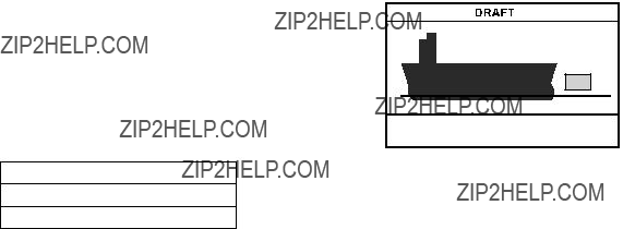
1.12 Draft
It is necessary to set the draft to use the DBS display mode, which shows depth below surface.
1.Select DBS with the MODE control.
???Confirm and set ships draft to use DBS mode.??? appears.
2.Press the DRAFT key to display the draft setting window.
0.0 m
3.Press the [+] key to increase the setting depth and
depth is
The above window disappears in 10 seconds.
The draft setting is displayed at the upper right corner and the range scale is shifted according to the draft setting.
8

2 MENU OPERATION
2.1 Menu Overview
The menu has several functions for advanced operation.
1.Select MENU with the MODE Selector.
INTERFERENCE REJECT
OFF IR1 IR2 IR3
PICTURE ADVANCE
SLOW FAST
TREND INDICATOR
1/2
??????: To select item
-+: To set option
2.Press the [???] or [???] key to select menu item. As you operate the [???] or [???] key, the selected item and its current setting appear in reverse video.
3.Press the
4.Set the MODE Selector in another position to close the menu.
2.2Suppressing Low Level Noise
When the automatic mode is on, the suppression setting is automatically adjusted. For manual override, do the following:
1.Select MENU with the MODE Selector.
2.Select CLUTTER by pressing the [???] key.
3.Press the
2.3 Suppressing Interference
Interference from other acoustic equipment operating nearby or other electronic equipment on your boat may show itself on the display.
To suppress interference, do the following:
1.Select MENU with the MODE Selector.
2.Select INTERFERENCE REJECT by pressing the [???] or [???] key.
3.Press the
Note that oversuppression will weaken the sensitivity.
9

2.4 Picture Advance
The picture advance speed determines how quickly the vertical scan lines run across the screen.
1.Select MENU with the MODE Selector.
2.Select PICTURE ADVANCE by pressing the [???] or [???] key.
3.Press the [+] or
2.5 Trend
The future trend of the seabed depths can be predicted over a specified period of time (See page 13). The trend index is set with the item TREND and appears at the top left corner. The default setting is ON.
?? is inclination angle of bottom.
2.6 Interval
The interval for sampling data for the LOGBOOK and HISTORY modes can be set with INTERVAL, among 5 s, 1 min and 2 min. The default setting is 1 min.
In this example, the setting of INTERVAL is
1 minute. That is, the depth and lat/long data are displayed at 1 minute intervals.
???2??>????????10?? ???10??>????????45?? ???45??>????????90??
10
3 SYSTEM MENU
3.1 System Menu
The system menu should be set just after installation and is not always necessary to be adjusted. If you change any items of the system menu or even if you open the system menu, the sounding picture will be cleared. There are three menus: 1,2,and 3.
1.Select MENU with the MODE Selector.
INTERFERENCE REJECT
OFF IR1 IR2 IR3
PICTURE ADVANCE
SLOW FAST
1/2
??????: To select item
-+: To set option
2.Press the [???] key several times to display following window.
CAUTION!
SYSTEM MENU IS ONLY
FOR INSTALLATION. DO
NOT CHANGE SETTINGS.
GO TO SYSTEM MENU?
NO YES
2/2
??? : To select item
-+: To set option
3.Select YES by pressing the [+] key.
Confirmation message ???ARE YOU SURE???? appears.
4.Press the [+] key again.
The system menu 1 appears.
5.With the cursor selecting MENU SELECT, operate the
SYSTEM MENU 1
??????: To select item
- +: To set option
Select other mode to exit.
??? Press [+] at menu 1. ??? Press
SYSTEM MENU 2
01 JAN 2001 00:00:00
??????: To select item
- +: To set option
Select other mode to exit.
??? Press [+] at menu 2. ??? Press
SYSTEM MENU 3
11
3.2 System Menu 1
DEPTH UNIT: Selects unit of depth measurement among meters, feet, or fathoms. Default setting is meters.
If "ft" or "fa" is selected, the depth unit is shown in red characters.
SPEED UNIT: Selects unit of speed measurement among knots, statute miles per hour, or kilometers per hour. Default setting is knots. Requires speed data, from external device.
COURSE: Selects heading reference; true or magnetic. Default setting is TRUE.
BOTTOM LOST: Turns on or off the bottom loss warning. ???ALARM??? sounds the alarm if the bottom signal is not detected. Default setting is ???ALARM??? (alarm is enabled).
GPS ALARM: The audible alarm may be released when the
INTERFACE: Selects I/O signal format between the
When selecting the ???1:98???, DPT has max. range in use (See page 24).
ALARM SOUND: Selects audio alarm sound among 1, 2 or 3. Default setting is 1.
1:Continuous sound
2:Intermittent sound; 0.5 s on and 0.5 s off.
3:Intermittent sound; 1 s on and 1 s off.
OS DATA: Selects own ship data display mode; DATA 1 or DATA 2. DATA1 is the default setting. If a navigation device is not connected to the
LANGUAGE: Currently English is only available.
3.3 System Menu 2
TIME ADJUST: Selects internal clock or external clock (UTC clock). Default setting is INTERNAL. For INTERNAL, set current day, month, year, hour, minute and second with [+],
SYSTEM MENU 2
01 JAN 2001 00:00:00
??????: To select item
- +: To set option
Select other mode to exit.
If EXTERNAL is selected, the screen changes as follows.
SYSTEM MENU 2
0:22:40
??????: To select item
- +: To set option Select other mode to exit.
TIME DIFFERENCE: Selects auto (UTC) or manual. Auto uses the time difference in ZDA (IEC
12

SYSTEM MENU 2
0:22:40
??????: To select item
- +: To set option Select other mode to exit.
3.4 System Menu 3
RANGE 1- 8: Activates or deactivates specific range scales. Default ranges are 5, 10, 20, 40, 100, 200, 400, and 800 (meters). Setting area is 2 m to 800 m. The ranges 20 m and 200 m can not be changed. They are essential in this equipment.
Note: Ranges must be set in numerical order. For example, if range 1 is 5 m and range 3 is 20 m, range 2 should be between 6 and 19 m.
Trend: The trend index shows the probable bottom shape over a specified time within
Set the Trend time with [+] or
13

4ECHO QUALITY SETTING
This chapter describes functions useful for improving echo sounding performance.
4.1 Demonstration Display
The demonstration program shows how the
1.Turn off the equipment.
2.Press the POWER Switch while pressing any key. Release the key when the following EXTENSION MODE display appears.
EXTENSION MODE
+ : TRANSDUCER SETTING
???: CLEAR MEMORY
???: DEMONSTRATION
SELECT MODE
3.Press the [???] key to select
DEMONSTRATION.
DEMONSTRATION
4.Press the [+] key to select ON.
5.Reset the power. "DEMO" appears above the depth indication on the echo sounder displays and at the top
!To return to the normal operation, select OFF at step 4 above. Restart the display unit after waiting 5 s.
4.2 Transducer Setting
After installing the equipment, set the transducer as follows.
1.Press the [+] key at the EXTENSION MODE display. The following window appears.
TRANSDUCER SETTING
??????: To select item
-+: To set option
2.Set as follows by using [???] or [???] to select an item and [+]
a)If only one transducer is installed, set XDR FORE field to 50 kHz or 200 kHz, according to actual installation. Leave the XDR AFT field as ??N/A.??
b)If two transducers are installed via the switch box
3.Reset the power.
Note: The default settings in the TRANSDUCER SETTING window are N/A. At the first
14

4.3 Bottom Level
If the depth indication is unstable or the seabed cannot be displayed steadily notwithstanding the adjustment of the control panel, you may adjust the bottom echo level.
 CAUTION
If the level is set too low, the
1.Press the MUTE ALARM key three times at the EXTENSION MODE. The
BOTTOM LEVEL
200kHz = 80 (20??? 200)
*: Either 200 kHz or 50 kHz is displayed depending on which frequency is used.
2.Set the level with the [+] or
3.Press the POWER switch to finish the adjustment. Wait about 5 s and then turn on the power again.
4.4 TVG Level
TVG (Time Varied Gain) compensates for propagation attenuation of the ultrasonic waves, reducing surface noise to provide a smooth display. The TVG lowers receiver sensitivity at the time of pulse emission and gradually increases it with time, thereby making objects of same reflectivity at different depths appear at the same intensity or colors on the display. The TVG working depth is down to approximately 150 m on the 200 kHz system and 350 m on the 50 kHz
system. Outside this range the echoes from the seabed and fish schools are received in full level. There is no perceivable deterioration in performance.
1.Press the DRAFT key three times at the EXTENSION MODE display. The TVG SELECT window appears.
TVG SELECT
200kHz = 5 (0??? 9)
2.Set the TVG curve with [+] or
3.Press the POWER switch to finish the adjustment. Wait 5 s, and then turn it on again.
4.5 Echo Offset
The echo offset feature functions to compensate for too weak or too strong echo level. If the on- screen echo level appears to be too weak or too strong and the level cannot be adjusted satisfactorily with the GAIN control, do the following to adjust echo level.
1.Press the DIM key three times at the EXTENSION MODE display. The ECHO OFFSET screen appears.
ECHO OFFSET
2.Set the offset with [+] or
3.Press the POWER switch to finish the adjustment. Wait about 5 s and then turn it on again.
15

5 OPERATION OF DIGITAL DEPTH INDICATOR
Omnipad
MENU ENT
DISP DIM
*
PWR
2.Press [ ] or [
 ] until the required value is reached. The range of adjustment is from 0 (Min.) to 63 (Max.). The default is 48.
3.Press the ENT key to set.
Note: The contrast is automatically set to the default when you turn on the power.
5.1.4 DEPTH MODE
The Digital Depth Indicator
5.1 Basic Operation
5.1.1 Turning on
Press the POWER key. The unit beeps and starts up with the
5.1.2 Adjusting panel dimmer
1.Press the DIM key.
2.Press [ ] to increase the dimmer or [
 ] to decrease it. The default is level 4.
3.Press the ENT key to finish the adjustment.
5.1.3Adjusting Contrast
1.Press the [??? ] key. The following window appears.
CONTRAST
48
EXIT: [ENT]
Depths are read either below transducer (keel) or below seaface irrespective of the main display. Select the mode as below:
1.Press the DISP key to select the wanted mode. The mode changes as below with each press.
DEPTH FORE 50kHz
123 m
BELOW TRANSDUCER
Depth below transducer
DEPTH FORE 50kHz
128 m
BELOW SURFACE*
DRAFT: 5.0 m
Depth below surface. Draft is determined on the main Display Unit
*: If the draft setting is
16

5.2Menu Operation
5.2.1Dimmer control
The dimmer is controlled either with the DIM key, or the optional Dimmer Controller. The method of control must be selected on the menu.
1.Press the MENU key to display the main menu.
2.Press [???] or [???] to select DIM CONTROL.
3.Press the ENT key. The following window appears.
4.Press [???] or [???] to select option desired.
PANEL ONLY: The illumination of the control panel is adjusted with the DIM key.
EXT CONTROLLER: Illumination of control panel is adjusted with the optional dimmer controller (hand dimmer box). The DIM key is inoperative.
EXT DISP: Not used.
5.Press the ENT key to set.
6.Press the MENU key to finish.
5.2.2 Selecting language
The language in use on the screen is either English or Japanese.
1.Press the MENU key to display main menu.
2.Press [???] or [???] to select the 
 /LANG.
3.Press the ENT key. The following window appears.
ENGLISH
4.Press [???] or [???] to select appropriate option. The default is English.
5.Press the ENT key to set.
6.Press the MENU key to finish.
5.2.3Selecting the unit of depth measurement
The unit of depth measurement is separately selected from the Main Display
1.Press the MENU key to display main menu.
2.Press [???] or [???] to select the UNITS.
3.Press the ENT key. The following window appears.
m ft fa
4.Press [???] or [???] to select unit. The default is meter (m).
5.Press the ENT key to set.
6.Press the MENU key to finish.
17

5.2.4Alarm
You can set turn alarm on or off. In the ON mode, if the main display unit activates the alarm, the
1.Press the MENU key to display main menu.
2.Press [???] or [???] to select ALARM.
3.Press the ENT key. The following window appears.
ON
OFF
4.Press [???] or [???] to select appropriate option. The default is ON.
5.Press the ENT key to set.
6.Press the MENU key to finish.
If the alarm sounds, press any key to silence it.
4.With YES selected, press the ENT key to start the test. The equipment tests the ROM and RAM, displaying the results as OK or NG (No Good). If NG appears, contact your dealer for advice.
TEST
ROM : OK
RAM : OK
PUSH KEY (STOP: PWR OFF)
CNT: 001
5.After "PUSH KEY" is displayed, press each key one by one. The name of the key pressed momentarily appears if the key is functioning properly.
The display shows the following message to inform you that the program is now going to check the LCD.
5.3 Diagnosis
The diagnostic test checks ROM, RAM, keys and LCD of the
1.Press the MENU key to display main menu.
2.Press [???] or [???] to select TEST.
3.Press the ENT key. The following window appears.
TEST START?
(STOP : PWR OFF)
ARE YOU SURE?
YES NO
<LCD CHECK>
ALL ON 2 SEC
ALL OFF 3 SEC
The whole display brightens for 2 seconds then turns off for 3 seconds. Test repeats. CNT, which is number of times the test has been consecutively executed, is counted up.
6.To stop the test, turn off the power.
5.4 Factory Setting
You can restore default settings to start operation anew. Press the POWER switch while pressing [???]. The message "RESET BACKUP DATA!" appears. After a while, all default settings are restored and the depth indication appears.
18

6 MAINTENANCE, TROUBLESHOOTING
 WARNING
Do not open the cover.
There are no
6.3 Transducer Maintenance
Marine life on the transducer face will result in a gradual decrease in sensitivity. Check the transducer face for cleanliness each time the ship is
6.1 Checking
Regular maintenance is essential for good performance. Checking the items listed in the table below on a regular basis will keep the equipment in good shape for years to come.
6.2 Cleaning the Display Unit
Dust or dirt on the display unit should be removed with a soft cloth. If desired a
6.4 Replacing the Fuse, Battery
If a fuse blows, find the cause before replacing it. Use only designated fuses. Using the wrong fuse will damage the unit and void the warranty.
Three types of fuses are used in the distribution box
The Digital Depth Indicator
A battery installed on a circuit board inside the display unit preserves data when the power is turned off. The life of the battery is about three years. When the battery voltage is low, ???battery??? NG appears at the
19
6.5 Troubleshooting
The table below provides simple troubleshooting procedures which you may follow to restore normal operation. If you cannot restore normal operation, contact your dealer.
20
6.6 Diagnostic Test
The diagnostic test checks the ROM, RAM, color bar and keyboard for proper operation.
1.Turn on the power while pressing any key. Release the keys when the following display appears.
EXTENSION MODE
+ : TRANSDUCER SETTING
???: CLEAR MEMORY
???: DEMONSTRATION
SELECT MODE
6.7 Test Pattern
The test pattern is used to check color performance.
1.Turn on the POWER SWITCH while pressing any key.
2.Press the BRILL key three times. Press the BRILL key again to change the test pattern as below.
BLACK
2.Press the
BATTERY : OK
PROGRAM No.: 0252297002
Key status
Position of Range knob Gain knob setting Position of Mode knob
???
WHITE
???
BLK RED GRN Blue YEL PPL Aqua WHT
3.The ROM, DRAM, SRAM and internal battery are checked and the results are displayed as OK or NG (No Good).
If NG appears, contact your dealer for advice.
4.Press and release each key (except the POWER switch) one by one. If the key is normal, its
5.Operate the controls. The RANGE and MODE control setting indications should be the same as actual control settings. The GAIN control setting indication should be between 0 and more than 230.
6.Press the POWER SWITCH to finish. Turn on the power again to resume operation.
???
3.Press the BRILL key again to return to the EXTENSION MODE menu.
21

6.8 Clearing the Memory
All menu settings can be cleared to start afresh. All default menu settings are restored when the memory is cleared. For your reference all default settings are shown in the menu tree at the end of this manual.
1.Turn on the power while pressing any key. Release the keys when the EXTENSION MODE menu appears.
2.Press the [???] key. The following window appears.
Restore factory settings.
+: YES
3.Press the [+] key to clear the memory. The following window appears.
DON??T TURN POWER OFF
UNTIL COMPLETED MEMORY CLEAR
Then the following display appears after the memory is cleared.
Set data to default.
4.After data is cleared, the EXTENSION MODE menu appears.
Note: The setting for the items LANGUAGE and TRANSDUCER in the system menu is not disturbed when the memory is cleared.
22

23

8DIGITAL INTERFACE (IEC
1. I/O Sentences
Input sentences of channel 1 (NAV IN)
RMA, RMC, GLL, GGA, VTG, ZDA
Output sentences of channel 2 (NAV OUT)
DBT, DPT, DBS (NMEA 0183)
Transmission interval
1 s for any sentence
Data transmission
Data is transmitted in serial asynchronous form in accordance with the standard referenced in 2.1 of IEC
The following parameters are used: Baud rate: 4800
Data bits: 8 (D7 = 0), parity none
Stop bits: 1
24

Load requirements as listener
Isolation: Optocoupler
Input Impedance: 560 ohms
Max. Voltage: ??15V
NAV OUT ports
TD1_A 1
TD1_B 2
.
.
.
TD1_A 6
TD1_B 7
.
NAV OUT 3 .
.
10
Total output for NAV OUT ports: Max. 20 mA
25
3. Sentence Description
DPT - Depth
1. Water depth relative to trancsducer, in meters
2. Offset from transeducer, in meters(see notes 1 and 2) 3. Maximum range scale in use
4. Checksum
NOTE1 "positive"=distance from transeduser to
NOTE2 For IEC applications the offset should always be applied so as to provide depth relative to the keel.
DBS ??? Depth below surface
1.Water depth, feet
2.Water depth, m
3.Water depth, fathoms
4.Checksum
DBT ??? Depth below transducer
1.Water depth, feet
2.Water depth, m
3.Water depth, fathoms
4.Checksum
26
GLL - Geographic position - latitude/longitude
1.Latitude, N/S
2.Longitude, E/W
3.UTC of position
4.Status: A=data valid, V=data invalid
5.Mode indicator(see note)
6.Checksum
NOTE Positioning system Mode indicator:
A = Autonomous
D = Differential
E = Estimated (dead reckoning)
M = Manual input
S = Simulator
N = Data not valid
The Mode indicator field supplements the Status field. The Status field shall be set to V=invalid for all values of Operating Mode except for A=Autonomous and D=Differential. The positioning system Mode indicator and Status field shall not be null fields.
27
GGA - Global positioning system (GPS) fix data
1.UTC of position
2.Latitude, N/S
3.Longitude, E/W
4.GPS quality indicator (see note)
5.Number of satllite in
6.Horizontal dilution of precision
7.Antenna altitude above/below mean sealevel, m
8.Geoidal separation, m
9.Age of differential GPS data
10.Differential reference station ID,
11.Checksum
NOTE
0 = fix not available or invalid
1 = GPS SPS mode, fix valid
2 = differential GPS, SPS mode, fix valid
3 = GPS PPS mode, fix valid
4 = Real Time Kinetic. Satellite system used in RTK mode with fixed integers 5 = Float RTK. Satellite system used in RTK mode with floating fingers
6 = Estimated (dead reckoning) mode
7 = Manual input mode
8 = Simulator mode
The GPS quality indicator shall not be a null field.
28
RMA - Recommended minimum specific
1.Status: A=data valid, V=blink, cycle or SNR warning
2.Latitude, degrees N/S
3.Longitude, degrees E/W
4.Time difference A, microseconds
5.Time difference B, microseconds
6.Speed over ground, knots
7.Course over ground, degrees true
8.Magnetic variation(see note 1),degree E/W
9.Mode indicator(see note 2)
10.Checksum
NOTE 1 - Easterly variation(E) subtracts from true course Westerly variation(W) adds to true course
NOTE 2 Positioning system Mode indicator:
A = Autonomous
D = Differential
E = Estimated (dead reckoning)
M = Manual input
S = Simulator
N = Data not valid
The Mode indicator field supplements the Status field. The Status field shall be set to V=invalid for all values of Operating Mode except for A=Autonomous and D=Differential. The positioning system Mode indicator and Status field shall not be null fields.
29
RMC - Recommended specific GPS/TRANSIT data
1.UTC of position fix
2.Status: A=data valid, V=navigation receiver warning
3.Latitude, N/S
4.Longitude, E/W
5.Speed over ground, knots
6.Course over ground, degrees true
7.Date: dd/mm/yy
8.magnetic variation, degrees E/W
9.Mode indicator(see note)
10.Checksum
NOTE Positioning system Mode indicator:
A = Autonomous
D = Differential
E = Estimated (dead reckoning)
M = Manual input
S = Simulator
N = Data not valid
The Mode indicator field supplements the Status field. The Status field shall be set to V=invalid for all values of Operating Mode except for A=Autonomous and D=Differential. The positioning system Mode indicator and Status field shall not be null fields.
30
VTG- Course over ground and ground speed
1.Course over ground, degrees true
2.Course over ground, degrees magnetic
3.Speed over ground, knots
4.Speed over ground, km/h
5.Mode indicator(see note)
6.Checksum
NOTE Positioning system Mode indicator:
A = Autonomous
D = Differential
E = Estimated (dead reckoning)
M = Manual input
S = Simulator
N = Data not valid
The positioning system Mode indicator field shall not be a null field.
ZDA - Time and date
1.UTC
2.Day, 01 to 31(UTC)
3.Month, 01 to 12(UTC)
4.Year(UTC)
5.Local zone hours, 00h to
6.Local zone minutes, 00 to +59 as local hours
7.Checksum
31

9 PARTS LOCATION, PARTS LIST
HEATSINK
MAIN BOARD 02P6280
ANLG 02P6281
INTERFACE
CON 02P6283
TB5
DISTRIBUTION BOX
INSIDE VIEW
32
33