MARINE RADAR
 MODEL 1712

 SAFETY INSTRUCTIONS
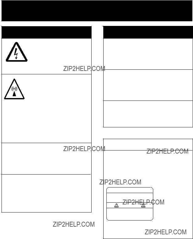
 WARNING
ELECTRICAL SHOCK HAZARD
Do not open the equipment.
Only qualified personnel should work inside the equipment.
Turn off the radar power switch before servicing the antenna unit. Post a warn- ing sign near the switch indicating it should not be turned on while the antenna unit is being serviced.
Prevent the potential risk of being struck by the rotating antenna and exposure to RF radiation hazard.
Do not disassemble or modify the equipment.
Fire, electrical shock or serious injury can result.
Turn off the power immediately if water leaks into the equipment or the equip- ment is emitting smoke or fire.
Continued use of the equipment can cause fire or electrical shock.
 WARNING
Use the proper fuse.
Fuse rating is shown on the equipment. Use of a wrong fuse can result in equipment damage.
Keep heater away from equipment.
Heat can alter equipment shape and melt the power cord, which can cause fire or electrical shock.
The useable temperature ranges are
Antenna unit:
Display unit:
CAUTION
WARNING LABEL
The warning label shown below is attached to the display unit. Do not remove this label. If the label is peeling off or is illegible, contact FURUNO for replacement.
 WARNING
To avoid electrical shock, do not remove cover. No
Code No.:
i
COMPLIANCE WITH R&TTE DIRECTIVE 1999/5/EC
This radar complies with the R&TTE Directive 1999/5/EC. In accordance with Article
Austria, Belgium, Cyprus, Denmark, Estonia, Finland, France, Germany, Greece, Hungary, Ireland, Italy, Latvia, Lithuania, Malta, Poland, Portugal, Slovenia, Spain, Sweden, The Netherlands, United Kingdom, Iceland, Norway
ii

TABLE OF CONTENTS
Declaration of Conformity
iii

FOREWORD
A Word to FURUNO MODEL 1712 Owners
FURUNO Electric Company thanks you for purchasing the MODEL 1712 Marine Radar. We are confident you will discover why the FURUNO name has become synonymous with quality and reliability.
For over 50 years FURUNO Electric Company has enjoyed an enviable reputation for quality and reliability throughout the world. This dedication to excellence is furthered by our extensive global network of agents and dealers.
Your radar is designed and constructed to meet the rigorous demands of the marine environment. However, no machine can perform its intended function unless properly installed and maintained. Please carefully read and follow the operation and maintenance procedures set forth in this manual.
We would appreciate feedback from you, the
Thank you for considering and purchasing
FURUNO.
Features
Your radar has a large variety of functions, all contained in a rugged plastic case. All controls respond immediately to the operator???s command and each time a key is pressed the corresponding change can be seen on the screen.
The main features of the MODEL 1712 are
???Traditional FURUNO reliability and quality in a compact,
???High definition
???Compact and
???Automatic control of sensitivity and sea clutter suppression for simplified operation.
???Targets can be displayed in gray on white background or vice versa, for optimal viewing under any lighting.
???
???Standard features include Display Shift, EBL, Echo Stretch, Target Trail, Guard Alarm, Interference Rejector, VRM, Zoom.
???Guard zone watches for targets entering (or exiting) a guard zone.
???Watchman feature transmits at set intervals to watch for targets entering (or exiting) the guard zone.
???Operates on 12 V or 24 V power and consumes approx. 40 watts power.
???Position in latitude and longitude, speed, and range and bearing to a waypoint can be shown in the bottom text area. (Requires navigation data input in NMEA 0183 format.)
???LCD equipped with temperature sensor which maintains viewability under temperature change.
iv

SYSTEM CONFIGURATION
ANTENNA UNIT
ANTENNA UNITRSB-0060
OR
DISPLAY UNIT
v
This page is intentionally left blank.
vi

1. PRINCIPLE OF OPERATION
What is Radar?
The term RADAR is an acronym meaning RAdio Detection and Ranging. It is a device which measures the time it takes for a pulsed signal to be reflected back from an object.
How Ships Determined Position Before
Radar
The use of echoes to determine position did not begin with radar. Ships would sound a short blast on their whistles, fire a shot, or strike a bell as an aid to navigation when running in fog near a rugged shoreline. The time between the origination of the sound and the returning of the echo indicated how far the ship was from the cliffs or the shore. The direction from which the echo was heard indicated the relative bearing of the shore.
How Radar Determines Range
Radar determines the range to the target by calculating the time difference between the transmission of a radar signal and the reception of the reflected echo. It is a known fact that radar waves travel at a nearly constant speed of 162,000 nautical miles per second. Therefore the time required for a transmitted signal to travel to the target and return as an echo to the source is a measure of the range to the target. Note that the echo makes a complete round trip, but only half the time of travel is needed to determine the
How Radar Determines Bearing
The bearing to a target found by the radar is determined by the direction in which the radar antenna is pointing when it emits an electronic pulse and then receives a returning echo. Each time the antenna rotates pulses are transmitted in the full 360 degree circle, each pulse at a slightly different bearing from the previous one.
Therefore, if one knows the direction in which the signal is sent out, one knows the direction from which the echo must return.
Radar Wave Speed and Antenna
Rotation Speed
The speed of the radar waves out to the target and back again as echoes is extremely fast compared to the speed of rotation of the antenna. By the time radar echoes have returned to the antenna, the amount of antenna rotation after initial transmission of the radar pulse is extremely small.
The Radar Display
Targets are displayed on what is called a Plan Position Indicator (PPI). This display is essentially a polar diagram, with the transmitting ship???s position at the center. Images of target echoes are received and displayed at their relative bearings, and at their distance from the PPI center.
With a continuous display of the images of targets, the motion of targets is also displayed.
See the figure on the next page for a comparison of actual situation and radar picture.
1

Figure
2
2. OPERATION
2.1 Turning the Radar On/Off
The [POWER] key turns the radar on/off. When turning on the power, the control panel lights and the timer displays the time remaining for warm up of the magnetron (the device which transmits radar pulses), counting down from 1:00 to 0:00.
Quick Start
Provided that the radar was once in use with the transmitter tube (magnetron) still warm, you can turn on the radar into TRANSMIT status without the
If the power switch has been turned off by mistake and you want to restart the radar promptly do the following:
1.Press the [POWER] key not later than five seconds after
2.After
2.2Transmitting,
After the power is turned on and the magnetron has warmed up,
Press the [TX] key to transmit. Echoes appear in four levels of digitized video according to echo strength. Note that when a target is beneath a marker (VRM, EBL, heading line and range ring) the part of the marker where the target lies is displayed in reverse video.
Note: If you press the [TX] key before the indication
When you won???t be using the radar for an extended period, but you want to keep it in a state of readiness, press the [TX] key to set the radar in
2.3 LCD Tone and Brilliance
1.Press the [TONE] key. The dialog box shown in Figure
TONE: 12
LOW HIGH
???
BRILL: 3
LOW ??? ??? HIGH
Figure
2. Press  or
or  to adjust tone
  or
or  to adjust brilliance
3

2.4 Control Description
MENU GUARD
HL OFF
EBL VRM
RINGS
RANGE
GAIN STC
FTC SHIFT
the menu.
TRAIL ZOOM
TONE TX
POWER
Turns EBL  on/off.
Decreases  the range.
Adjusts receiver  sensitivity.
Suppresses  rain clutter.
Turns target trails  on/off.
Adjusts LCD tone  and brilliance.
HL OFF

 Turns VRM on/off. EBL VRM Press with [EBL] to
turn range rings
RINGS
on/off.
Figure
4

2.5 Indications and Markers
Watchman
Guard zone
Cursor
3M TRAIL  G (IN)
FTC 
ES 
IR 
Target trails setting Guard alarm (IN or OUT) Rain clutter suppressor Echo stretch Interference rejector
EBL
Heading line
VRM


 Range rings
EBL bearing
VRM range 
Figure
2.6 Selecting the Range
The range selected automatically determines the range ring interval, the number of range rings and pulse repetition rate.
Press the [+] or
Range  6.0 NM
2.7 Receiver Sensitivity
The [GAIN] key adjusts the sensitivity of the receiver. It works in precisely the same manner as the volume control of a broadcast receiver, amplifying the signals received.
You can adjust the sensitivity manually, or let the unit do it automatically. In either case, the proper setting is such that the background
Range ring interval
2.0
045.0?? 
 3.35 NM
noise is just visible on the screen. Adjust the sensitivity on the highest range since the background noise is clearer on that range.
If you set up for too little sensitivity, weak echoes may be missed. On the other hand excessive sensitivity yields too much background noise; weak targets may be missed because of the poor contrast between desired echoes and the background noise on the
Figure
display.
5

Automatic adjustment of sensitivity
1.Press the [GAIN] key once or twice to display the screen shown in Figure
AUTO GAIN MOD
LOW 
 HIGH
HIGH
1 2 3
Figure
2.Press  or
or  to set level desired: 1, Low; 2, Normal; 3, High.
Manual adjustment of sensitivity
1.Transmit on long range.
2.Press the [GAIN] key once or twice to display the screen shown in Figure
Figure
3.Press  or
or  to set level desired. 61 levels are available.
Note: The dialog boxes for adjustment of sensitivity are automatically erased when there is no Omnipad operation for 10 seconds. To erase them quicker, press the [GAIN] key after completing the setting.
2.8 Suppressing Sea Clutter
In rough weather, returns from the sea surface are received over several miles around own ship and mask nearby targets. This situation can be improved by properly using the [STC] key.
If the STC setting is too low, targets will be hidden in the clutter, while if it is set too high, both sea clutter and targets will disappear from the display. In most cases adjust the key until clutter has disappeared to leeward, but a little is still visible windward.
A common mistake is too
Figure
Automatic sea clutter control
1.Press the [STC] key once or twice to show the dialog box shown in Figure
AUTO STC MOD
LOW 
 HIGH
HIGH
1 2 3
Figure
2.Press  or
or  to set level desired: 1, Low; 2, Normal; 3, High.
6

Manual adjustment of sea clutter control
1.Press the [STC] key once or twice to display the dialog box shown in Figure
Figure
2.Press  or
or  to set level desired. 61 levels are available.
Note: The dialog boxes for adjustment of STC are automatically erased when there is no Omnipad operation for 10 seconds. To erase them quicker, press the [STC] key after completing the setting.
2.9 Suppressing Rain Clutter
In adverse weather, clouds, rain or snow produce
FTC
Figure
2.10 Range Rings
The range rings are the concentric circles around own ship and they provide an estimate of target range. The selected range scale automatically determines the number of rings and their interval is displayed at the
To turn the range rings on or off, press the [EBL] and [VRM] keys together.
2.11 Cursor
The cursor is always displayed and functions to measure the range and bearing to a target. Operate the Omnipad to place the cursor on the inside edge of the target for range measurement or the center of the target for bearing measurement. The range and bearing to the cursor appear at the bottom
6.0 NM
2.0
Target
 Cursor
Figure
7

2.12 Menu Operation
The menu contains ten functions which normally do not require frequent adjustment in everyday operation. Basic menu operation is as below.
Basic menu operation
1. Press the [MENU] key to display the menu.
PRESS ??? /??? TO SELECT MENU
Press ??? at DIMMER; ??? at DSPL ON STBY to change page. Default settings in highlight.
PRESS ??? /??? TO SELECT MENU
Figure
2. Press  or
or  to select item
3. Press  or
or  to select option.
4. Press the [MENU] key to register your selection and close the menu.
Table
2.13 Heading Line
The heading line indicates the ship???s heading and it is the solid line which appears at zero degrees on the bearing scale.
To temporarily erase the heading line to look at targets existing dead ahead of own ship, press the [MENU] and [GUARD] keys together.
Release the keys to display the line again.
2.14 Control Panel Illumination
1.Press the [MENU] key to open the menu.
2.Select DIMMER.
3.Select level desired; 3 is the highest level of brilliance.
4.Press the [MENU] key to register your selection and close the menu.
8

2.15 Measuring the Range
The bearing to a target can be measured by the range rings, by the cursor (see paragraph 2.11) and by the VRM (Variable Range Marker).
2.16 Measuring the Bearing
The bearing to a target can be measured by the cursor (see paragraph 2.11) and by the EBL (Electronic Bearing Line).
Measuring range by the range rings
Count the number of rings between the center of the display and the target. Check the range ring interval at the top
Measuring range by the VRM
1.Press the [VRM] key to turn on the VRM.
2.Within 10 seconds after turning on the VRM, that is, while "VRM" is highlighted, press  (increase radius) or
  (decrease radius) to place the VRM on the inside edge of the target.
3.Check the VRM readout at the bottom left- hand corner on the screen.
Note: The VRM becomes stationary when the [VRM] key is pressed a second time, or 10 seconds elapses without pressing  or
or  . When the VRM is stationary "VRM" is not highlighted.
Figure
To erase the VRM, press the [VRM] key until the VRM disappears.
Measuring bearing by the EBL
1.Press the [EBL] key to turn on the EBL.
2.Within 10 seconds after turning on the EBL, that is, while "EBL" is highlighted, press  (counterclockwise) or
  (clockwise) to bisect the target with EBL.
3.Check the EBL readout at the bottom left- hand corner on the screen.
Note: The EBL becomes stationary when the [EBL] key is pressed a second time, or 10 seconds elapses without pressing  or
or  . When the EBL is stationary "EBL" is not highlighted.
6.0 NM
2.0
Target

 Cursor
EBL
EBL bearing
Figure
To erase the EBL, press the [EBL] key until the EBL disappears.
9
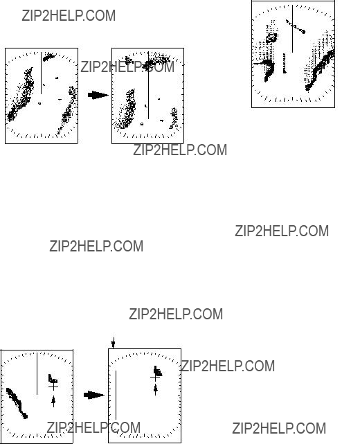
2.17 Shifting the Display
Your vessel's position can be shifted backward by 1/3 of the range to increase the forward range without changing the range or size of targets.
Press the [SHIFT] key to turn the shifted display on/off.
Press [SHIFT]
Figure
2.18 Zoom
The zoom feature allows you to double the size of the area between your vessel and any location within the current range to take a closer look at an area of interest.
1.Select location to zoom with the cursor.
2.Press the [ZOOM] key.
ZOOM on (flashing)
ZOOM
2.19 Target Trails
Target trails are simulated afterglow of target echoes that represent their movements relative to own ship.
3M TRAIL  Trail time (3 min)
Figure
Starting target trail
Press the [TRAIL] key to start the echo trail function. "TRAIL" and the target trail time selected appear at the top
Canceling target trail
Press the [TRAIL] key to erase target trails and target trail indications.
Trail time
Press
Cursor
Cursor [ZOOM]
Figure
3.To turn off the zoom function, press the [ZOOM] key again.
Note 1: Zoom is inoperative when the display is shifted.
Note 2: Zoom is not available on 0.125 (1/8) nm range.
Trail brilliance
1.Press the [MENU] key to open the menu.
2.Select TRAIL BRILL (on page 2 of the menu).
3.Select HIGH or LOW as appropriate.
4.Press the [MENU] key to register your selection and close the menu.
10
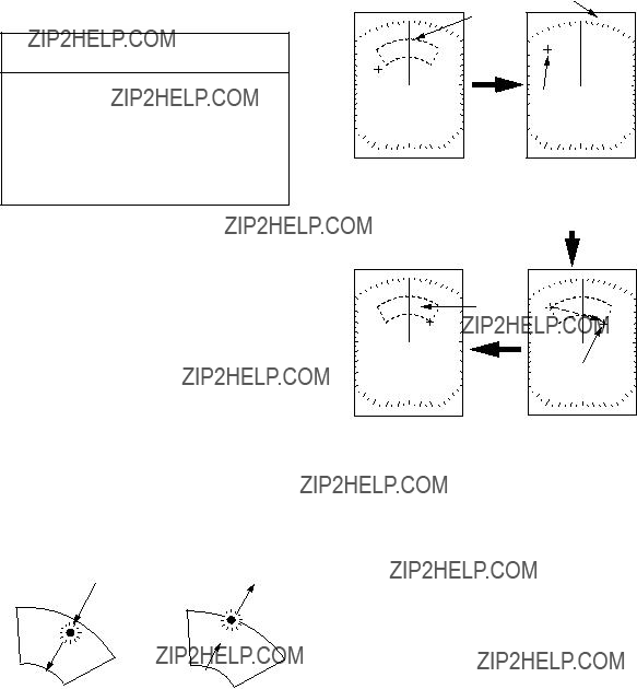
2.20 Guard Alarm Zone
The guard alarm allows the operator to set the desired range and bearing for a guard zone. When ships, islands, landmasses, etc. violate the guard zone the offending target flashes and an aural alarm sounds to call the operator???s attention. The alarm is triggered against targets entering or exiting the guard zone depending on guard zone type as below.
 CAUTION
*The alarm should not be relied upon as the sole means for detecting possible collision situations.
*STC, FTC and GAIN controls should be properly adjusted to be sure the alarm system does not overlook target echoes.
How guard zone type is determined
Setting a guard zone
1.Operate the Omnipad to place the cursor at the top
2.Operate the Omnipad to place the cursor at
the bottom
Asterisk blinking
After the guard zone is set, the radar starts searching for targets inside the guard zone for about 8 to 12 seconds. The results of the search are shown at the top
G (IN): This is the inward guard alarm and it means no target was found in the guard zone. Thereafter the aural alarm sounds against targets which enter the guard zone.
GUARD
Guard zone
Guard zone completed.
2)Drag cursor to bottom right corner of zone and press [GUARD].
G (OUT): This is the outward guard alarm and it means a target was found in the guard zone. Thereafter the aural alarm sounds against all targets which exit the guard zone.
(a) Inward guard alarm (b) Outward guard alarm
Figure
Figure
3.Eight to twelve seconds later the indication G (IN) or G (OUT) replaces the indication
GUARD.
Note: When the radar range is less than one half of the guard zone range, the guard zone disappears and the indication "UP RNG" replaces G (IN) or G (OUT). If this happens, raise the range to redisplay the guard zone.
11

Silencing the aural alarm
When a target violates the guard zone, the target flashes and the aural alarm sounds. You can silence the aural alarm by pressing the [GUARD] key. When this is done, GUARD, displayed in reverse video, replaces G (IN) or G (OUT). This means the guard alarm is temporarily deactivated. Press the key again to reactivate the alarm.
Canceling the guard zone and guard alarm
Press and hold down the [GUARD] key more than two seconds to erase the guard zone.
2.21 Interference Rejector
Mutual radar interference may occur in the vicinity of another shipborne radar operating in the same frequency band (9 GHz). It is seen on the screen as a number of bright spikes either in irregular patterns or in the form of usually curved
1.Press the [MENU] key to open the menu.
2.Select INT. REJECT.
3.Select ON or OFF as appropriate.
4.Press the [MENU] key to register your selection and close the menu.
Figure
2.22 Echo Stretch
On long ranges target echoes tend to shrink in the range direction, making them difficult to see. On short and medium ranges such as 1.5, 3 and 6 nm range scales, the same sized targets get smaller on screen as they approach own ship. This is due to the inherent property of the radiation pattern produced by the antenna. To enhance target video, use the echo stretch feature.
Echo stretch
ON
ES
Echo
Echo stretched in range direction
Figure
1.Press the [MENU] key to open the menu.
2.Select ECHO STRETCH.
3.Select ON or OFF as appropriate.
4.Press the [MENU] key to register your selection and close the menu.
ES appears at the top
Note 1: Echo stretch magnifies not only small target pips but also returns from sea surface, rain and radar interference. For this reason, make sure that these types of interference have been sufficiently suppressed before activating the echo stretch.
Note 2: Echo stretch is not available on the ranges between 0.125 and 0.75 nautical miles.
12
2.23 Watchman
The watchman function periodically transmits the radar for about one minute to check for targets in the guard zone. If a target has entered or exited the guard zone the aural alarm sounds, watchman is canceled and the radar starts transmitting. This feature is useful when you do not need to observe the radar continuously but want to be alerted to radar targets in the guard zone. When the radar starts transmitting, the buzzer sounds to alert the operator.
Watchman * Timer appears and countdowns starts. time to Tx when 1:00 remains
in
Figure
Turning watchman on/off
1.Set a guard zone. (See ???Setting a guard zone??? on page 11.)
2.Press the [MENU] key to open the menu.
3.Select WATCHMAN.
4.Select transmitting interval or turn watchman off. .
5.Press the [MENU] key to register your selection and close the menu.
"WATCHMAN" appears at the top
Note: If no guard zone is set, the buzzer sounds when the radar starts transmitting.
Canceling watchman
Press any key at any time. If done while transmitting, watchman is disabled and the normal display appears. In
2.24 Navigation Data
With navigation data input in NMEA 0183 format (IEC
Navigation data includes position, course, speed, and range and bearing to destination waypoint (if set on navaid).
6.0 NM
2.0
Waypoint mark
Bearing and range to waypoint *- Bearing suffixed with M
(Magnetic bearing) or T (True bearing). Own ship position
Figure
Note 1: External sensor must be capable of outputting such data to show it on this radar. Note 2: A location shows three bars (- -
Note 3: To receive data from multiple equipment, all data must be combined into one data line by a
Note 4: Magnetic and true bearing may be selected alternately by pressing and holding down the [GAIN] key.
Turning on the navigation data display
1.Press the [MENU] key to open the menu.
2.Select NAV DATA.
3.Select ON.
4.Press the [MENU] key to conclude.
13

Turning the waypoint mark on/off
The destination waypoint set on a navigator may be shown on the radar display. It is shown by a dashed ring which is connected to the screen center by a dashed line. (See Figure
2.25 Displaying Navigation
Data During
Navigation data may be displayed during
1.Press the [MENU] key to open the menu.
2.Select DSPL ON STBY.
3.Select NAV.
4.Press the [MENU] key to register your selection and close the menu.
WP 215.5?? M 12.5NM
CSE SPD 210.5?? 12KT
LL 34?? 42.25' N 135?? 24.12' E
TD 36378.1 59096.4
TEMP 18.5?? C
DEPTH
1 2 5 M
Figure
Note: Nav data can be accepted from two
sources: navigator and video sounder. When two of the same type of device is outputting data to the radar and the data is not identical, the two sets of data are displayed alternately.
Unit of measurement for depth and water temperature
The unit of measurement for depth and water temperature (external sensors required) can be selected with the [EBL] key in the sequence of Meters/Centigrade, Feet/Fahrenheit, Fathoms/Centigrade.
Note: The unit of depth measurement available depends on the data sentence output by external equipment as below.
DBT(Ver.1.5) Meters, feet and fathoms DPT(Ver.2.0) Meters only
2.26 Echoes in Black or White
The default setting displays echoes in shades of black on a white background. However, you may reverse this arrangement as shown below to suit lighting conditions. Note that the default setting is restored whenever the power is turned off.
1.Press the [MENU] key to open the menu.
2.Select VIDEO.
3.Select RVS.
4.Press the [MENU] key to register your selection and close the menu.
2.27 Selecting Ranges to Use
This radar has 14 ranges, some you may not require. You can select the ranges to use as follows:
1.Press the [MENU] key to open the menu.
2.Select RANGE.
3.Select (highlight) range to use and press the [EBL] key. Ranges in use are highlighted.
4.Press the [MENU] key to register you selection and close the menu.
Note: At least two ranges are left on (highlighted).
14
3. RADAR OBSERVATION
3.1 General
Minimum range
The minimum range is defined by the shortest distance at which, using a scale of 1.5 or 0.75 nm, a target having an echoing area of 10 m2 is still shown separate from the point representing the antenna position.
It is mainly dependent on the pulselength, antenna height, and signal processing such as main bang suppression and digital quantization. It is a good practice to use a shorter range scale as far as it gives favorable definition or clarity of picture.
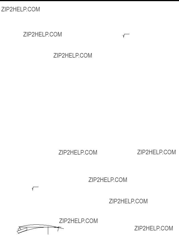
Maximum range
The maximum detecting range of the radar, Rmax, varies considerably depending on several factors such as the height of the antenna above the waterline, the height of the target above the sea, the size, shape and material of the target, and the atmospheric conditions.
Under normal atmospheric conditions, the maximum range is equal to the radar horizon or a little shorter. The radar horizon is longer than the optical one by about 6% because of the diffraction property of the radar signal. The Rmax is given in the following equation.
Rmax= 2.2 x ( h1 + h2 )
Where;
Rmax: Radar horizon (nautical miles)
h1: antenna height (m)
h2: target height (m)
Radar horizon
Optical horizon
Figure
For example, if the height of the antenna above the waterline is 9 meters and the height of the target is 16 meters, the maximum radar range is;
Rmax= 2.2 x ( 9 + 16 ) = 2.2 x (3 + 4) = 15.4 nm
It should be noted that the detection range is reduced by precipitation (which absorbs the radar signal).
Radar resolution
There are two important factors in radar resolu- tion (discrimination): bearing resolution and range resolution.
Bearing resolution
Bearing resolution is the ability of the radar to display as separate pips the echoes received from two targets which are at the same range and close together. It is proportional to the antenna length and reciprocally proportional to the wavelength.
Range resolution
Range resolution is the ability to display as separate pips the echoes received from two targets which are on the same bearing and close to each other. This is determined by pulselength only. Practically, a 0.08 microsecond pulse offers the discrimination better than 35 m as do so with all FURUNO radars.
Test targets for determining the range and bearing resolution are radar reflectors having an echoing area of 10 m2.
15

Bearing accuracy
One of the most important features of the radar is how accurately the bearing of a target can be measured. The accuracy of bearing measurement basically depends on the narrowness of the radar beam. However, the bearing is usually taken relative to the ship???s heading, and thus, proper adjustment of the heading line at installation is an important factor in ensuring bearing accuracy. To minimize error when measuring the bearing of a target, put the target echo at the extreme position on the screen by selecting a suitable range.
Radar antenna
Radar mast
Shadow sector
Figure
Range measurement
Measurement of the range to a target is also a very important function of the radar. Generally, there are two means of measuring range: the fixed range rings and the variable range marker (VRM). The fixed range rings appear on the screen with a predetermined interval and provide a rough estimate of the range to a target. The variable range marker???s diameter is increased or decreased so that the marker touches the inner edge of the target, allowing the operator to obtain more accurate range measurements.
3.2 False Echoes
Occasionally echo signals appear on the screen at positions where there is no target or disappear even if there are targets. They are, however, recognized if you understand the reason why they are displayed. Typical false echoes are described in this paragraph.
Shadow sectors
Funnels, stacks, masts, or derricks in the path of the antenna block the radar beam. If the angle subtended at the antenna is more than a few degrees, a
Multiple echoes
Multiple echoes occur when a transmitted pulse returns from a solid object like a large ship, bridge, or breakwater. A second, a third or more echoes may be observed on the display at double, triple or other multiples of the actual range of the target as shown below. Multiple reflection echoes can be reduced and often removed by decreasing the gain (sensitivity) or properly adjusting the [STC] key.
True echo
Target
Own ship
Multiple echo
Figure
16

Sidelobe echoes
Every time the radar pulse is transmitted, some radiation escapes on each side of the beam, called sidelobes. If a target exists where it can be detected by the side lobes as well as the main lobe, the side lobe echoes may be represented on both sides of the true echo at the same range. Sidelobes show usually only on short ranges and from strong targets. They can be reduced through careful reduction of the gain or proper adjustment of the [STC] key.
Target A
Target B 
(Spurious) Target B
(True)
Figure
Virtual image
A relatively large target close to your ship may be represented at two positions on the screen. One of them is the true echo directly reflected by the target and the other is a false echo which is caused by the mirror effect of a large object on or close to your ship as shown in the figure below. If your ship comes close to a large metal bridge, for example, such a false echo may temporarily be seen on the screen.
Target ship
Own ship
True echo
Figure
17

3.3 SART
Note: The SART (Search and Rescue Transponder) information below is excerpted from IMO SN/Circ 197 Operation of Marine Radar for SART Detection.
A Search and Rescue Transponder (SART) may be triggered by any
When the range to the SART is reduced to about 1 nm, the radar display may show also the 12 responses generated during the fast sweeps. These additional dot responses, which also are equally spaced by 0.64 nm, will be interspersed with the original line of 12 dots. They will appear slightly weaker and smaller than the original dots.
Position of
SART
Low speed sweep signal
Sweep start
High speed sweep signal
Figure
General procedure for detecting SART response
1.Use the range scale of 6 or 12 nm as the spacing between the SART responses is about 0.6 nm (1125 m) to distinguish the SART.
2.Turn off the automatic clutter suppression.
3.Turn off the Interference Rejector.
General remarks on receiving SART
SART range errors
When responses from only the 12 low frequency sweeps are visible (when the SART is at a range greater than about 1 nm), the position at which the first dot is displayed may be as much as 0.64 nm beyond the true position of the SART. When the range closes so that the fast sweep responses are seen also, the first of these will be no more than 150 meters beyond the true position.
Radar bandwidth
This is normally matched to the radar pulselength and is usually switched with the range scale and the associated pulselength. Narrow bandwidths of
Any radar bandwidth of less than 5 MHz will attenuate the SART signal slightly, so it is preferable to use a medium bandwidth to ensure optimum detection of the SART.
18
Radar side lobes
As the SART is approached, sidelobes from the radar antenna may show the SART responses as a series of arcs or concentric rings. These can be removed by the use of the
Gain
For maximum range SART detection the normal gain setting for long range detection should be used, that is, with background noise speckle visible.
STC control
For optimum range SART detection, this control should be set to the minimum. Care should be exercised as a wanted target in sea clutter may be obscured. Note also that in clutter conditions the first few dots of the SART response may not be detectable, irrespective of the setting of the
Some sets have automatic/manual
FTC control
This should be used normally (to break up areas of rain) when trying to detect a SART response which, being a series of dots, is not affected by the action of the
Some sets have automatic/manual
When the range to the SART is reduced to about 1 nm, the radar display may show also the 12 responses generated during the fast sweeps. These additional dot responses, which also are equally spaced by 0.64 nm, will be interspersed with the original line of 12 dots. They will appear slightly weaker and smaller than the original dots.
19

3.4 Racon (Radar Beacon)
A racon is a radar transponder which emits a characteristic signal when triggered by a ship???s radar (usually only the 3 centimeter band). The signal may be emitted on the same frequency as that of the triggering radar, in which case it is superimposed on the ship's radar display automatically.
The racon signal appears on the PPI as a radial line originating at a point just beyond the position of the radar beacon or as a Morse code signal (see figure below) displayed radially from just beyond the beacon.
Racon
Figure
20

4. MAINTENANCE,
TROUBLESHOOTING
 WARNING
Do not open the equipment.
Hazardous voltage which can cause electrical shock exists inside the equipment. Only qualified personnel should work inside the equipment.
4.1 Maintenance
Regular maintenance is important for good performance. A maintenance program should be established and should at least include the items listed in Table
Table
4.2 Replacing the Fuse
The fuse (5A) in the power cable protects the equipment against reverse polarity of ship???s mains, overcurrent and equipment fault. If the fuse blows, find the cause before replacing it.
 CAUTION
Use the proper fuse.
Use of a fuse of the wrong amperage will damage the equipment and void the warranty.
21
4.3 Troubleshooting
Table
Table
4.4 Magnetron Replacement
When the magnetron has expired distant targets cannot be seen on the display. If this occurs, contact a FURUNO agent or dealer about replacement of the magnetron.
4.5 Antenna Motor Belt Replacement
When the antenna motor belt has worn out, the sweep is not synchronized with antenna rotation, which results in abnormal picture. If this occurs, contact a FURUNO agent or dealer about replacement.
22
SPECIFICATIONS OF MARINE RADAR
MODEL 1712
SP - 1
SP - 2
SP - 3

INDEX

Nishinomiya
Pub. No.
( TATA ) MODEL 1712
The paper used in this manual is elemental chlorine free.
Your Local Agent/Dealer
FIRST EDITION : MAY 2000
H3 :MAR. 11, 2005
*00080898400*
*00080898400*
* 0 0 0 8 0 8 9 8 4 0 0 *
*OME34890H30*
*OME34890H30*
* O M E 3 4 8 9 0 H 3 0 *