INSTALLATION MANUAL
COLOR GPS/PLOTTER


 SAFETY INSTRUCTIONS
Safety Instructions for the Installer
 WARNING
Do not work inside the equipment unless totally familiar with electrical circuits.
Hazardous voltage which can shock, burn or cause serious injury exists inside the equip- ment.
Turn off the power at the mains switchboard before beginning the installation.
Post a sign near the switch to indicate it should not be turned on while the equipment is being installed.
Fire, electrical shock or serious injury can result if the power is left on or is applied while the equipment is being
 CAUTION
Ground the equipment to prevent electrical shock and mutual interference.
Confirm that the power supply voltage is compatible with the voltage rating of the equipment.
Connection to the wrong power supply can cause fire or equipment damage. The voltage rating appears on the label at the rear of the display unit.
Use the correct fuse.
Use of a wrong fuse can cause fire or equipment damage.
Keep the following compass safe distance.
Standard Steering
Display unit 0.8 m 0.5 m

SYSTEM CONFIGURATION
The
(for
Antenna unit
Receives signal from GPS satellite and beacon reference station
Display unit
Ship's position is calculated in longitude and latitude from signal received from the an- tenna unit and displayed on the screen.
(for
Category of Units
Ship's mains
External equipment (Autopilot, etc.)
DGPS beacon receiver
:Option
:Local Supply
Rectifier
Ship's mains 100/110/115/220/230 VAC 1 , 50/60 Hz
i

EQUIPMENT LISTS
Standard supply
*: Refer to Packing list at the end of this manual.
Optional equipment
ii
EQUIPMENT LISTS
Optional equipment (con???t)
iii
EQUIPMENT LISTS
This page is intentionally left blank.
iv

1.INSTALLATION
1.1Installation of Display Unit
Mounting considerations
The display unit can be installed on a tabletop, on the overhead or flush mounted in a console or panel.
Tabletop, overhead mounting methods
When selecting a mounting location for the display unit keep the following in mind:
???Keep the display unit out of direct sunlight.
???The temperature and humidity should be moderate and stable.
???Locate the unit away from exhaust pipes and vents.
???The mounting location should be well ventilated.
???Mount the unit where shock and vibration are minimal.
???Keep the unit away electromagnetic field generating equipment such as motor, generator.
???For maintenance and checking purposes, leave sufficient space at the sides and rear of the unit and leave slack in cables.
???A magnetic compass will be affected if placed too close to the display unit. Observe the following compass safe distances to prevent disturbance to the magnetic compass:
Standard compass: 0.8 meters
Steering compass: 0.5 meters
1

1. INSTALLATION
Mounting procedure
Follow the procedure below to mount the display unit on a tabletop or the overhead.
Tabletop, overhead mounting
1.Fix the hanger by four pan head screws 5 X 16.
2.Screw knob bolts in display unit, set it to hanger, and tighten knob bolts.
3.Attach hard cover to protect LCD.
Tabletop, overhead mounting of display unit
Flush mounting
Note: Use supplied pan head screws when the thickness of the bulkhead is from 11 to 14 mm. For bulkhead which exceeds 14 mm in thickness the length of the pan head screws should be bulkhead thickness+7.8??1.5 mm. Also the length of B should max. 8mm.
B A
1.Prepare a cutout in the mounting location whose dimensions are as shown on the next page.
2.Fix the display unit by six pan head screws M4 X 20. Refer to the outline drawing on page
2
1. INSTALLATION
4.5
Flush mount
Flush mounting of display unit
1.2Installation of Antenna Unit
Mounting considerations
Install the antenna unit referring to the installation diagram on page
???Select a location out of the radar beam. The radar beam will obstruct or prevent reception of the GPS satellite signal.
???The location should be well away from a VHF antenna. A GPS receiver is interfered by a harmonic wave of a VHF antenna.
???There should be no interfering object within the
???Mount the antenna unit as high as possible. Mounting the antenna unit as high as possible keeps it free of interfering objects and water spray, which can interrupt reception of GPS satellite signal if the water freezes.
???Do not shorten the antenna cable.
???If the antenna cable is to be passed through a hole which is not large enough to pass the connector, you may unfasten the connector with a needle nose pliers and
Shield
Clamp nut
Center pin (soldered)
Connector shell
How to assemble the connector
3

2.WIRING
All wiring are terminated at the rear of the display unit.
Earth terminal
Antenna unit
Displa unit
External equipment
Display unit, rear view
Power cable
Connect the power cable to the power connector. Connect the leads to the battery (12 or 24 VDC); white to plus(+) terminal and black to
Cable connector
Power cable w/fuse (3A)
Lead wire
Black White
BATTERY
Connecting the power cable to the battery
4

2. WIRING
Antenna unit
Connect the antenna unit cable to the ANT connector.
Ground
The display unit contains several CPUs. While they are operating, they radiate noise, which can interfere with radio equipment. Ground the unit to prevent interference. The grounding wire should be 1.25 sq or larger and as short as possible. Connect the grounding wire to ship's ground. On a fiberglass boat, it is best to install a ground plate that measures about 20 cm by 30 cm on the outside of the hull bottom to provide a ground point. If this is not practical, the engine block can be used.
 CAUTION
Ground the equipment to prevent electrical shock and mutual interference.
Note: Use a ???closed??? lug to make the ground connection at the display unit. Do not use an  ).
).
Extending antenna cable length
The standard cable is 10 m long. For extension, in case of the
5

2. WIRING
Extension cable
Fabricate the end of the antenna cable and attach the coaxial connector. Details are shown on the next page.
Antenna unit
Conversion: Connector cable assy.
Fabricate locally. (See the next page.)
Cable extension
Antenna unit
: Connector
Antenna cable
To display unit
15 m
Cable extension
Waterproofing connector
Wrap connector with vulcanizing tape and then vinyl tape. Bind the tape end with
Waterproofing connector
6

2. WIRING
How to attach the
Cover with
Remove outer sheath and armor by the dimensions shown left.
Expose inner sheath and shield by the dimensions shown left.
Cut off insulator and core by 10mm.
Trim shield here.
Insulator
Trim aluminum tape foil here.
Twist shield end.
Ship on clamp nut, gasket and clamp as shown left.
Fold back shield over clamp and trim.
Cut aluminum foil at four places, 90?? from one another.
Fold back aluminum foil onto shield and trim.
1
5
Pin
Clamp nut
Shell
Solder through the hole.
Expose the insulator by 1mm.
Expose the core by 5mm.
Slip the pin onto the conductor. Solder them together through the hole on the pin.
Insert the pin into the shell. Screw the clamp nut into the shell.
(Tighten by turning the clamp nut. Do not tighten by turning the shell.)
Fabrication of coaxial cable
7

3.INITIAL SETTINGS
3.1NMEA Setting
NMEA port
This setting should be done when connecting with other equipment, autopilot, radar or remote display.
1.Press the [MENU] key.
2.Press the CONFIGURATION soft key.
3.Press the SETUP NMEA PORT1 soft key.
4.Press the cursor pad to select FORMAT.
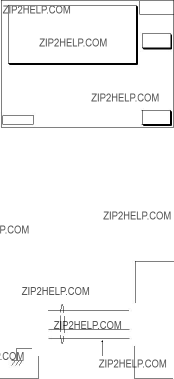
5.Press the EDIT soft key to display the following window.
Output format window (PORT 1)
6.Select NMEA version depending on the specification of the equipment connected. The selected item is indicated by black button.
7.Press the ENTER soft key.
8.Press the [PLOT] key to return to the plotter display.
8

3. INITIAL SETTINGS
DGPS port
Set the following when connecting with DGPS beacon receiver
Note: Signal level for DGPS port is RS232C.
1.Press the [MENU] key.
2.Press the CONFIGURATION soft key.
3.Press the SETUP NMEA/DGPS PORT 2 soft key.
4.Select FORMAT, and then press the EDIT soft key.
The following window appears.
Output format window (PORT 2)
5. Select NMEA version. The selected item is indicated by black button.
Note 1: Note that you cannot setup sentences when you select RTCM104 at the format.
Note 2: For
6.Press the ENTER soft key.
7.Press the [PLOT] key to finish.
9

3. INITIAL SETTINGS
3.2Output Data Sentences
Select output data sentences for external equipment as follows.
1.Press the [MENU] key.
2.Press the CONFIGURATION soft key.
3.Press the SETUP NMEA PORT1 soft key.
4.Press the SELECT SNTNC. soft key to display the SELECT SENTENCE window.
*: BWR for Rhumb line BWC for Great circle
Select sentence window
5.Select data sentence you want to output.
6.Press the ON/OFF soft key. To output data, select ON.
7.Repeat to select other sentences.
8.Press the RETURN soft key.
9.Press the [PLOT] key to return the plotter display.
10

*1: Cannot be input consecutively.
*2: Output automatically when LC or LA is selected.
3.3Antenna Height
Enter height of antenna above water. (Default setting: 5 m)
1.Press the [MENU] key.
2.Press the GPS/DGPS/TD OPTIONS soft key.
3.Press the GPS SETUP OPTIONS soft key.
4.Select ANT. HEIGHT.
5.Press the EDIT soft key.
ANT. HEIGHT
0 0 5 m
Ant. height window
6.Enter the height (3 digits) of the antenna above sea level using the numeric keys.
If you enter wrong antenna height, press the CLEAR soft key.
7.Press the ENTER soft key.
8.Press the [PLOT] key to return the plotter display.
11
3. INITIAL SETTINGS
3.4DGPS Setting
When external DGPS beacon receiver
1.Press the [MENU] key.
2.Press the GPS/DGPS/TD OPTIONS soft key.
3.Press the DGPS/WAAS SETUP OPTIONS soft key.
DGPS options window
4.Select DGPS/WAAS MODE and press the EDIT soft key.
5.Select DGPS or AUTO and press the ENTER soft key. WAAS: WAAS data can be received.
AUTO: DGPS, WAAS or GPS data can be automatically received, The order of priority is DGPS, WAAS and GPS.
Note: If the external DGPS beacon receiver
Connection with
<1 <
<3 <
<7 < GND
12
3. INITIAL SETTINGS
6.Select BEACON FREQUENCY by the cursor pad.
7.Press the EDIT soft key to display the following window.
BEACON FREQUENCY
???
AUTO
MANUAL
???
???
284.0 kHz
Beacon frequency window
8.Select AUTO or MANUAL by the cursor pad. When you select MANUAL, operate the cursor pad to move the cursor to frequency dialog box. And press the arrow key to select the frequency desired.
9.Press the [ENTER] key.
10.Select BEACON BAUD RATE by the cursor pad.
11.Press the EDIT soft key to display the following window. Beacon baud rate cannot be set when BEACON FREQUENTRY is set to AUTO.
BEACON BAUD RATE
???
200  100
100  50
50
???
Beacon baud rate window
12.Select beacon baud rate corresponding to DGPS reference station to use.
13.Press the [ENTER] key.
14.Press the [PLOT] key to return the plotter display.
13

4.INCORPORATION OF DGPS
BEACON RECEIVER KIT (for
The DGPS beacon receiver
14

4. INCORPORATION OF DGPS BEACON RECEIVER KIT (for
Disassembly
Procedure
1.Turn off the power. Wait at least one minute before opening the cover, to allow capacitors to discharge.
2.Remove nuts attached to DGPS, NMEA and power supply connectors at the rear of the display unit.
Screws X 6 B
Screws X 6 A
 WARNING
Do not connect the power cable with the cover re- moved.
Panel/chassis assembly
Connector gasket
Removing cover assembly
3.Remove nuts and washer attached to ANT connector.
4.Remove twelve screws at rear of the display unit to detach panel/chassis assembly from cover assembly.
Discard six screws A (3X12).
15

4. INCORPORATION OF DGPS BEACON RECEIVER KIT (for
Installation of beacon receiver
Procedure
1. Disconnect 8P connector as shown in the figure below.
Chassis assembly
A
 Connector
Dismounting chassis assembly
2.Dismount chassis assembly from panel assembly by disconnecting connector shown in the figure above.
3.Cut the cable ties as shown in the figure below.
J8
Cut cable tie.
Cutting cable ties
16

4.INCORPORATION OF DGPS BEACON RECEIVER KIT (for
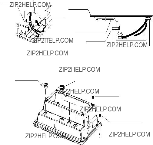
4.Dismount heat sink from chassis assembly by unfastening four screws on the ANLG board and disconnecting the connector of the mini pin coaxial cable.
Handling of Coaxial Cable
???Do not touch the connector with bare hands; use gloves.
???Use radio pincers to remove, and pull out straightly.
???Plug in connector straightly.
Screws X 4
ANLG board
Mini pin connector
A
Mini pin coax. cable
Heat sink
Chassis assembly
5.Take off the mini pin coaxial cable from J2 on the
6.Open the lid of
7.Connect cable assy.
17

4. INCORPORATION OF DGPS BEACON RECEIVER KIT (for
Notch
Beacon receiver
Cable assy.
Beacon receiver
8.Connect cable assy.
9.Close the lid of the
10.Connect connector assy.
11.Fasten the
M3X10, 4 pcs.
Connect to
J8 on ANLG
Board.
Connect to
J2 on
Connect to
J106 on
MAIN Board.
Connect to J107 on MAIN Board
Cable Assy.
Cover of
Notch
Beacon Receiver Board
Heat sink
Installation of DGPS beacon receiver
18

4.INCORPORATION OF DGPS BEACON RECEIVER KIT (for
12.Connect the cable assy.
13.Pass the mini pin coaxial cable of J1 on the
14.Mount the ANLG board on the heat sink.
Mini pin coxial cable
Heat sink
Connect cable assy. J1 of
to J8 of ANLG board
to J106 of MAIN board
Cable tie
Clamp
Connect mini pin coaxial cable between J1 of
Wiring the Cable assembly
15.Mount chassis assembly on the panel assembly. Connect 8P connector and 6P connector to Main board as shown in the figure below.
Chassis assembly
A
 Connector
Panel assembly
Attaching chassis assembly
19
4. INCORPORATION OF DGPS BEACON RECEIVER KIT (for
16.Fasten 8P connector cable and 6P connector cable by cable tie as shown in the figure below. Fasten mini pin coaxial cable by cable tie
Note: After connecting, pull up cable to remove slack so as not to pinch the cable between cover panel assembly.
Cable tie
ANLG board
PH8P
J106
J8
Mini pin coax. cable
PH6P
J107
Cable tie
Attaching cable tie
17.Reassemble the display unit.
Use new screws size 3X12 (supplied).
Nut, washer Torque: 1.37~1.57 N??m
Cover assembly
Screws X 6
Torque:
0.74~0.78 N??m
New screws X 6
Torque:
0.74~0.78 N??m
Remounting the cover
Note: When reattaching the cover, confirm the following parts are attached. Shield gasket, cover gasket (See the next page.)
Connector gasket (See the page 15.)
20

4. INCORPORATION OF DGPS BEACON RECEIVER KIT (for
Cover gasket
Shield gasket(1)
Shield gasket (2)
Gaskets
21

4. INCORPORATION OF DGPS BEACON RECEIVER KIT (for
Checking the beacon receiver
1.Press the [MENU] key.
2.Press the CONFIGURATION soft key.
3.Press the SYSTEM MENU soft key.
4.Press the SELF TEST soft key.
5.Press the MEMORY???I/O TEST soft key to display the following message.
*Special connections are required to check these ports. Otherwise, NG appears.
Memory, I/O Test Display
6.Confirm that BEACON RECEIVER: OK is displayed.
7.Press the RETURN soft key.
8.Press the [PLOT] key to return the plotter display.
22
DOUBLE ASTERISK DENOTES COMMONLY USED EQUIPMENT.
?????????????????????????????????????????? DIMENSIONS IN DRAWING FOR REFERENCE ONLY.???
DOUBLE ASTERISK DENOTES COMMONLY USED EQUIPMENT.
?????????????????????????????????????????? DIMENSIONS IN DRAWING FOR REFERENCE ONLY.???

????????????????????? ????????????
DOUBLE ASTERISK DENOTES COMMONLY USED EQUIPMENT.
?????????????????????????????????????????? DIMENSIONS IN DRAWING FOR REFERENCE ONLY.???

???????????????
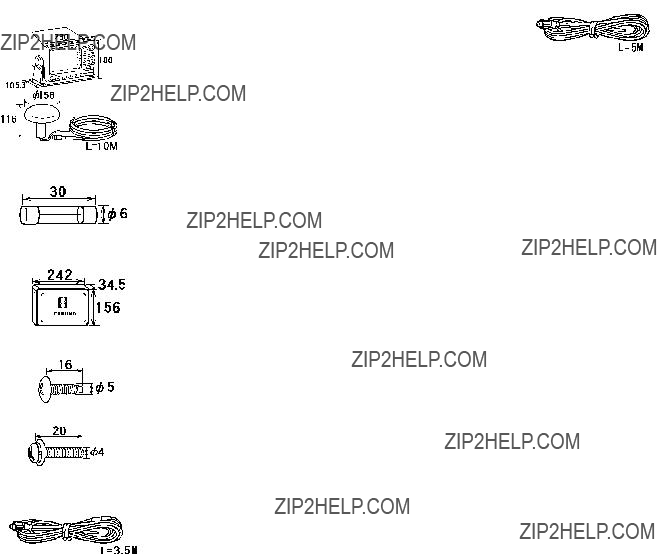
INSTALLATION MATERIALS
?????????????????? ???????????????????????? ?????? ???????????????.
?????????????????????????????????????????? DIMENSIONS IN DRAWING FOR REFERENCE ONLY.???

?????????????????? ???????????????????????? ?????? ???????????????.
?????????????????????????????????????????? DIMENSIONS IN DRAWING FOR REFERENCE ONLY.???


The paper used in this manual is elemental chlorine free.
Nishinomiya,
Pub. No.
(KAMI )
???FURUNO Authorized Distributor/Dealer
A : AUG . 2002
A1 : JUL . 21, 2004
*00080935910*
*00080935910*
* 0 0 0 8 0 9 3 5 9 1 0 *