GPS NAVIGATOR
DGPS NAVIGATOR
GPS NAVIGATOR
DGPS NAVIGATOR

Nishinomiya, Japan
Telephone :
Telefax :
PUB.No.
( YOSH )
Your Local Agent/Dealer
FIRST EDITION : MAY. 1999
K : APR. 26,2002
*00080877701*
*00080877701*
* 0 0 0 8 0 8 7 7 7 0 1 *
*OME43990K00*
*OME43990K00*
* O M E 4 3 9 9 0 K 0 0 *

 SAFETY INSTRUCTIONS
Safety Instructions for the Operator
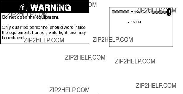
 WARNING
Do not open the equipment.
Only qualified personnel should work inside the equipment.
Do not disassemble or modify the equipment.
Fire, electrical shock or serious injury can result.
Immediately turn off the power at the switchboard if the equipment is emitting smoke or fire.
Continued use of the equipment can cause fire or electrical shock. Contact a FURUNO agent for service.
Keep heater away from equipment.
A heater can melt the equipment???s power cord, which can cause fire or electrical shock.
Use the proper fuse.
A 1A fuse is provided in the power/data cable. Use only a 1A
 CAUTION
Do not use the equipment for other than its intended purpose.
Improper use of the equipment can result in personal injury or equipment damage.
No one navigation device should ever be solely replied upon for the navigation of a vessel.
Always confirm position against all avail- able aids to navigation, for safety of vessel and crew.
GPS position and velocity accuracies are controlled by the U.S. Department of Defense. Position may be degraded
up to 100 meters.
i
Safety Instructions for the Installer
 WARNING
Do not open the cover unless totally familiar with electrical circuits and service manual.
Improper handling can result in electrical shock.
Turn off the power at the switchboard before beginning the installation.
Fire or electrical shock can result if the power is left on.
Be sure that the power supply is compatible with the voltage rating of the equipment.
Connection of an incorrect power supply can cause fire or equipment damage. The voltage rating of the equipment appears on the label above the power connector.
DO NOT CUT THE ANTENNA CABLE.
See the instructions on the CAUTION SHEET and the chapter on installation.
 CAUTION
Ground the equipment to prevent mutual interference.
Observe the following compass safe distances to prevent interference to a magnetic compass:
ii

TABLE OF CONTENTS
2.PLOTTER DISPLAY
OVERVIEW
3. WAYPOINTS (MARKS)
4. ROUTES
5. NAVIGATION
6. ALARMS
7. OTHER FUNCTIONS
8.MAINTENANCE &
TROUBLESHOOTING
9. INSTALLATION
APPENDIX
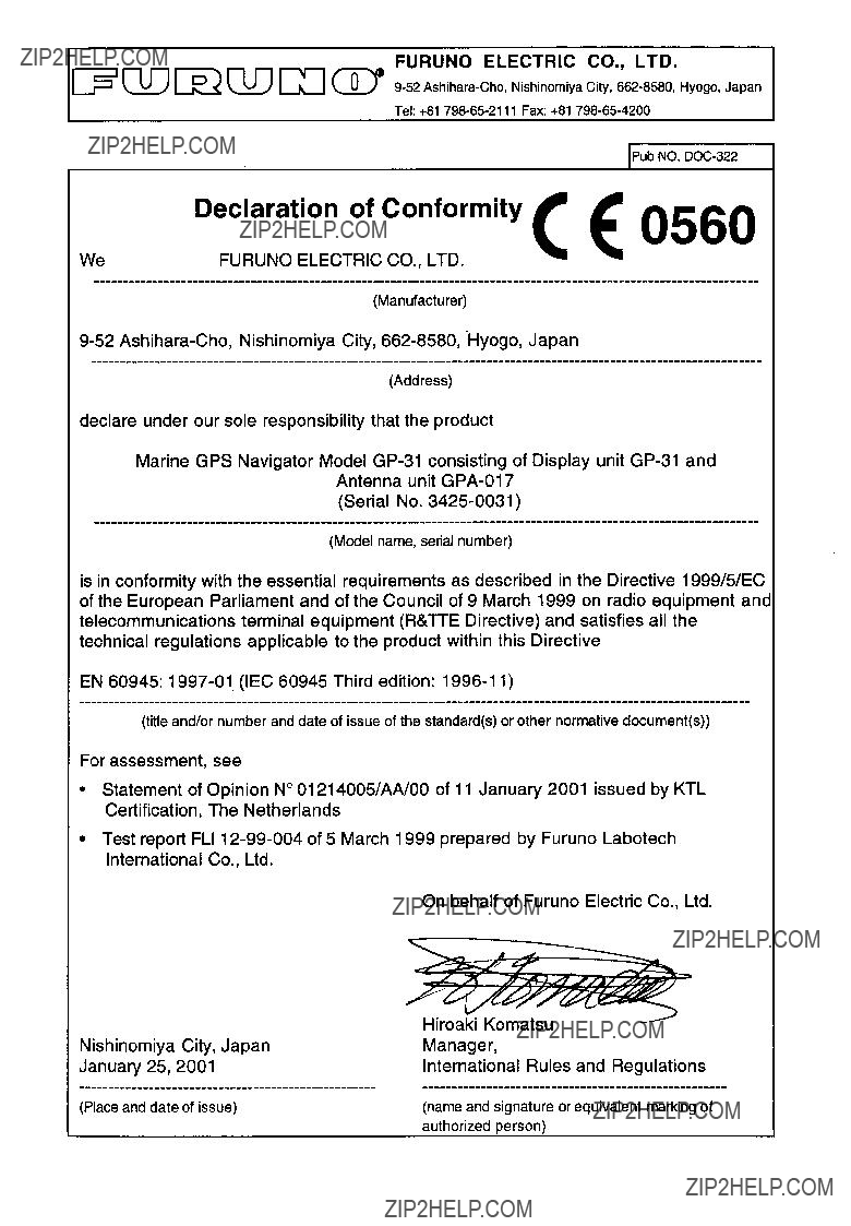
Declaration of Conformity
iii

FOREWORD
A Word to
Congratulations on your choice of the GP- 31 GPS Navigator,
For over 50 years FURUNO Electric Com- pany has enjoyed an enviable reputation for innovative and dependable marine electron- ics equipment. This dedication to excellence is furthered by our extensive global network of agents and dealers.
Your navigator is designed and constructed to meet the rigorous demands of the marine environment. However, no machine can per- form its intended function unless installed, operated and maintained properly. Please carefully read and follow the recommended procedures for installation, operation, and maintenance.
We would appreciate hearing from you, the
Thank you for considering and purchasing FURUNO equipment.
Features
The
The
The main features of the
???A DGPS beacon receiver (external) may be connected to the
???Comprehensive navigation data displays
???Storage for 950 waypoints and 50 routes
???Alarms: Arrival, Anchor Watch, XTE
???Man overboard feature records latitude and longitude or TD (Loran C or Decca) coordinates at time of man overboard and provides continuous updates of range and bearing when navigating to the MOB po- sition.
???
???Bright 95 x 60 mm LCD with adjustable contrast and brilliance
???Autopilot (option) may be connected, and steering data output to the autopilot.
???Unique ???Highway??? display provides a graphic presentation of ship???s progress toward a waypoint.
???Own ship???s position may be shown in lati- tude and longitude or TD (Loran C or Decca).
???Waypoint and route data can be uploaded from a PC or downloaded to a PC.
iv

SYSTEM CONFIGURATION
v
Optional equipment
vi

1.OPERATIONAL OVERVIEW
1.1Control Description
Press once: Zoom, centering, or escapes from current opera- tion, depending on display in use.
Press twice: Opens menu.
Selects display mode.
MENU ENT
DISP GOTO
MARK
MOB
DIM
PWR
Cursor Pad
 Shifts cursor and display.
  Selects items on menus.
Registers items on menus.
Sets/cancels destination.
Inscribes mark, MOB mark on the display.
Long press: Turns power off.
Touch and release: Turns power on. Opens the display for adjustment of dimmer and contrast.
Figure
Removing the hard cover
To remove the hard cover, squeeze it at its top and bottom right (or left) corners and pull it toward you.
Pressure
Pressure

1.2Turning On and Off the Power
Turning on the power
Press the [DIM/PWR] key. The unit beeps and then starts up with the
Your equipment takes about two minutes to find its position when turned on for the very first time.
The equipment shows receiver status indi- cations at the top
Table
DOP: Dilution of Precision. The index for
Note: Position accuracy also depends on satellite position.
Turning off the power
Press and hold down the [DIM/PWR] key until the screen goes blank, approx. three seconds. The time remaining until power off is counted down on the display.
1.3Adjusting Display Dimmer and Contrast
1.Press the [DIM/PWR] key with a touch-
D I M M E R ( 1 ~ 8 )
???  ??? 4
??? 4
C O N T R A S T ( 0 ~ 6 3 )
t

 s 4 1
s 4 1
E X I T : [ E N T ]
Figure
2.To adjust the dimmer, press ??? or ???. Cur- rent setting is shown to the right of ?????????.
3.To adjust the contrast, press t or s.
Current setting is shown to the right of
???s???.
4.Press the [ENT] key to finish.
Note: If you turn off the power with minimum contrast,nothing appears on the display when you turn on the power again.Adjust the contrast as described above.
1.4 Display Modes
Your unit has five display modes: Plotter Display, Highway Display, Steering Display, Nav Data Display and User Display (digital data or speedometer). Press the [DISP] key to select a display mode. Each time the key is pressed, the display mode changes in the sequence shown below.
Figure
Note: Position data can be shown in latitude and longitude or TDs (Loran C or Decca).
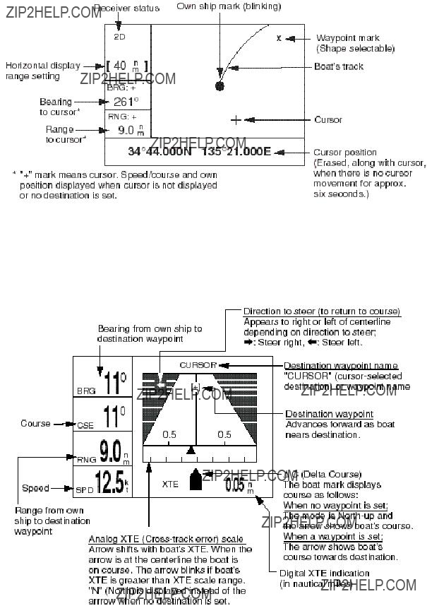
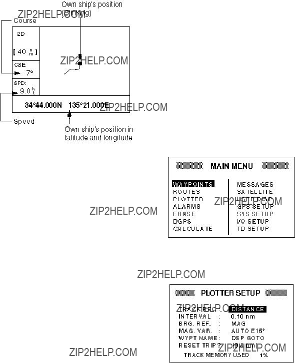
Plotter display
The plotter display traces own ship???s track, and shows position, course, speed, and hori- zontal display range setting.
Figure
Highway display
The highway display provides a
Figure
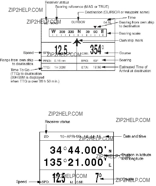
Steering display
The steering display provides steering information such as ship???s speed, course; range, bearing, ETA and TTG
Figure
Nav data display
The nav data display shows position in latitude and longitude (or TDs), course, speed, date and time.
Figure
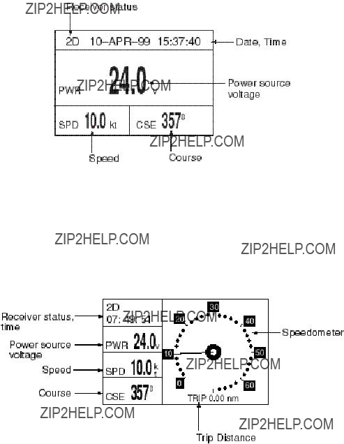
User displays
Two user displays are available, digital and speedometer, and the operator may select which to display. The default display is the digital display.
Digital display
The digital display shows digital navigation data. The user may choose what data to dis- play in the three cells below the receiver status, date and time indications. The choices of data are speed, course, range, bearing,
Figure
Speedometer display
The speedometer display provides both digital and analog speed readouts. Additionally it provides three cells of data (below the receiver status and time indication) which the user may choose. The choices are the same as those for the digital display.
Figure
1.5 Basic Menu Operation
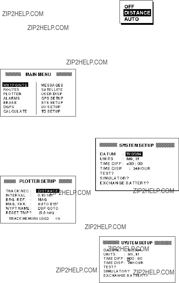
Most operations of the your unit are car- ried out through the menu. Below is a quick introduction to how to select a menu and change menu settings. If you get lost in op- eration, press the [MENU] key to return to the MAIN menu. A complete menu tree appears in the Appendix.
1.Press the [MENU] key once or twice to display the menu.
Figure
Once: At the steering display, nav data display, user display.
Twice: At the plotter display, highway display.
2.Operate the cursor pad to select a menu and press the [ENT] key. For example, select PLOTTER and press the [ENT] key.
Figure
3.Press ??? or ??? to select menu item. For example, select the TRACK REC field.
4.Press the [ENT] key. A window showing options appears. (The figure below shows the options available for TRACK REC.)
Figure
5.Press ??? or ??? to select option desired.
6.Press the [ENT] key.
7.Press the [MENU] key twice to finish.
How to enter alphanumeric data
In some instances it is necessary to enter alphanumeric or character data. The ex- ample below shows how to enter a time dif- ference of
1.Press the [MENU] key once or twice to display the menu.
2.Select SYS SETUP and press the [ENT] key.
Figure
3.Press ??? to select the TIME DIFF field.
4.Press the [ENT] key. A cursor circum- scribes ???+???. This cursor appears when- ever selected data can be changed with the cursor pad.
Figure
5.Press ??? to display
6.Press  to send the cursor to the next digit.
7.Press ??? or ??? to display 0.
8.Press  to send the cursor to the next digit.
9.Press ??? or ??? to display 6.
10.Press  to send the cursor to the next digit.
11.Press ??? or ??? to display 3.
12.Press  to send the cursor to the last digit.
13.Press ??? or ??? to display 0.
14.Press the [ENT] key.
15.Press the [MENU] key twice to finish.
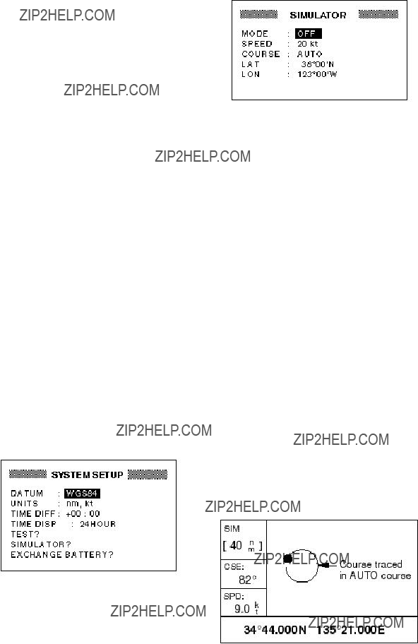
1.6 Simulator Display
The simulator display provides simulated operation of this unit. You may set the speed manually and the course manually or auto- matically. All controls are operative ??? you may enter marks, set destination, etc.
1.Press the [MENU] key twice to display the menu.
2.Select SYS SETUP and press the [ENT] key.
Figure
4.Press the [ENT] key. A window appears which shows the choices ON or OFF.
5.Select ON and press the [ENT] key.
6.Press the [ENT] key, enter speed to use for the simulation with the cursor pad, and press the [ENT] key.
7.Press the [ENT] key.
8.Select course entry method (AUTO or MANU) and press the [ENT] key. For manual entry of course, press the [ENT] key again, enter course with the cursor pad, and press the [ENT] key again. (The AUTO course tracks a circular course.)
9.Press the [ENT] key, enter latitude (usu- ally current latitude) with the cursor pad, and press the [ENT] key.
10.Press the [ENT] key, enter longitude (usually current longitude), and press the [ENT] key.
11.Press the [MENU] key twice.
12.Select the PLOTTER display with the [DISP] key. SIM appears at the upper
Figure
3.Select ???SIMULATOR???? and press the [ENT] key.
Figure
13.To turn off the simulator display, select OFF at step 5 in this procedure, press the [ENT] key, and press the [MENU] key twice to finish.
Note: If the power is reset while the simu- lator display is in use, the indication SIMU- LATION MODE appears at the top of the screen at the next power up, in addition to the indication SIM. SIMULATION MODE disappears when any key is pressed.
This page is intentionally left blank.
2. PLOTTER DISPLAY OVERVIEW
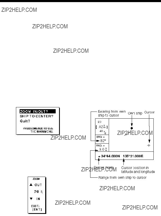
2.1Enlarging/Shrinking the Display Range
You may increase or decrease the display range on the plotter and highway displays. The horizontal range in the plotter display is available among .02 (40 yd), .05 (101 yd), 0.1 (202 yd), 0.2 (405 yd), 0.5, 1, 2, 5, 10, 20, 40, 80, 160 and 320 nautical miles. (Nautical mile is the default unit of display range. Display range may also be shown in kilometers or miles. Ranges shorter than the value 0.5 are also shown in yards or meters.) The horizontal range in the high- way display is available among 0.2, 0.4, 0.8, 1, 2, 4, 8 and 16 nautical miles.
1.Press the [MENU] key. The zoom, ship centering window appears.
2.2 Shifting the Cursor
Use the cursor pad to shift the cursor. The cursor moves in the direction of the arrow or diagonal pressed on the cursor pad.
Cursor state and data
Cursor state determines what data is shown on the display.
Cursor turned on
Cursor position is displayed in latitude and longitude or TDs (depending on menu set- ting) at the bottom of the plotter display when the cursor is on. The range and bear- ing from own ship to the cursor appear at the
Figure
Note: The prompt ???SHIP TO CENTER???? does not appear when the highway display mode is active.
2.Press the [ENT] key. The zoom window appears.
Figure
3.Press ??? (increase) or ??? (decrease) to select range desired.
4.Press the [ENT] key to finish.
Figure
Cursor turned off
The cursor is erased when there is no cur- sor pad operation for about six seconds. Ship???s position, speed and course appear at the left side of the plotter display when the cursor is off.
Figure
2.3 Shifting the Display
The display can be shifted on the plotter display. Operate the cursor pad to place the cursor at an edge of the screen. The dis- play shifts in the direction opposite to cur- sor pad operation.
2.4Centering Own Ship???s Position
When own ship tracks off the display the own ship mark is automatically returned to the screen center. You can also return it manually as follows:
1.Press the [MENU] key.
2.Select SHIP TO CENTER?.
3.Press the [ENT] key.
2.5Changing Track Plotting Interval, Stopping Plotting of Track
To trace the ship???s track, the ship???s position is stored into the memory at an interval of distance or automatic recording (memory capacity: 1,000 points). For distance, a shorter interval provides better reconstruc- tion of the track, but the storage time of the track is reduced. When the track memory becomes full, the oldest track is erased to make room for the latest.
1.Press the [MENU] key once or twice to display the menu.
Figure
2.Select PLOTTER.
3.Press the [ENT] key.
Figure
4.The cursor should be on the TRACK REC field. Press the [ENT] key. The track recording method selection win- dow appears.
Figure
5.Select OFF, DISTANCE or AUTO and then press the [ENT] key.
OFF: Track is neither recorded or plot- ted. This setting is useful when you do not need to record track, for example, when returning to port.
DISTANCE: Track is recorded and plot- ted at the distance interval set. AUTO: Plotting and recording interval changes with chart scale selected.
If you selected DISTANCE, enter the re- cording interval as follows:
a)Press the [ENT] key.
b)Press  or
or  to select digit to change.
c)Press ??? or ??? to change value.
d)Press the [ENT] key after setting.
6.Press the [MENU] key twice to finish.
2.6 Erasing Track
All track can be erased. Track cannot be restored once erased, therefore be abso- lutely sure you want to erase all track.
1.Press the [MENU] key once or twice to display the menu.
2.Select ERASE and press the [ENT] key to display the ERASE menu.
Figure
3.Select ???TRACK???? and press the [ENT] key. The message shown in Figure
Figure
4.Press the [ENT] key to erase all track.
5.Press the [MENU] key twice to finish.
This page is intentionally left blank.

3. WAYPOINTS (MARKS)
3.1 Entering Waypoints
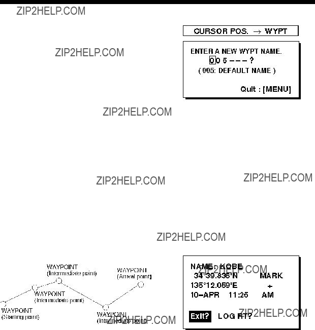
In navigation terminology a waypoint is a particular location on a voyage whether it be a starting, intermediate or destination waypoint. Your unit can store 950 waypoints. Waypoints can be entered on the plotter display four ways: at cursor po- sition, at own ship???s position, through the menu (manual input of L/L or TD), and by MOB position.
Entering a waypoint by the cursor
1.On the plotter display, use the cursor pad to place the cursor on the location you want to make a waypoint.
2.Press the [ENT] key. The following win- dow appears.
Figure
3.The cursor is on the second line of the display. This is where you may enter waypoint name, which may consist of six characters. (The number shown is the youngest empty waypoint number. If you would rather have the unit regis- ter the waypoint under that number, and you do not need to change mark shape or enter a comment, press the [ENT] key twice to register the waypoint and fin- ish.) To enter KOBE as the waypoint name, for example, do the following:
a)Press ??? or ??? to display K.
b)Press  to move the cursor to the next column and press ??? or ??? to dis- play O.
c)Press  to move the cursor to the next column and press ??? or ??? to dis- play B.
d)Press  to move the cursor to the next column and press ??? or ??? to dis- play E.
e)Press the [ENT] key. The following window appears.
Figure
4.This window is where you can select mark shape, enter a comment, and log the waypoint to a route. (If you do not need to change mark shape, enter a comment, or save waypoint to a route, select ???Exit???? and press the [ENT] key to finish.) How to log waypoints to a route will be discussed in the chapter on routes.
a)Use the cursor pad to place the cur- sor under MARK.
b)Press the [ENT] key.
c)Select mark desired with ??? or ???.
Figure
d) Press the [ENT] key.
e)The cursor is on the date/time field. Press the [ENT] key.
f)Enter a comment (max. 16 charac- ters) with the cursor pad (the same as you did when entering waypoint name) and press the [ENT] key. To create a space, select ???blank??? char- acter. To remove all characters which follow the cursor, select the underline.
g)The cursor is on ???Exit?.??? Press the [ENT] key.
h)Press the [ENT] key again to finish.
Note: ???LOG RT???? function is explained in the chapter on routes.
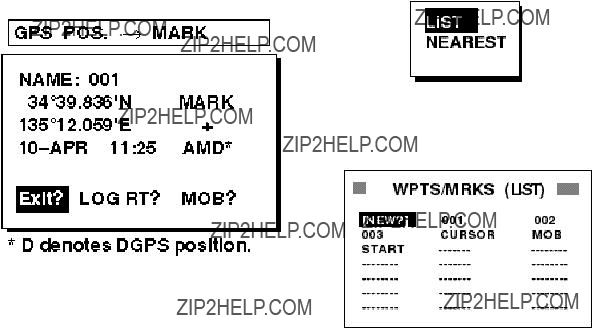
Entering a waypoint at own ship???s position
1.Press the [MARK/MOB] key on any dis- play. The following window appears.
5.The cursor is on the date/time field. To change the date to a comment, press the [ENT] key, enter a comment with the cursor pad, and press the [ENT] key again.
6.Place the cursor on ???Exit?.??? Press the [ENT] key to finish.
Entering a waypoint through the waypoint list
1.Press the [MENU] key once or twice to display the menu.
2.Select WAYPOINTS.
3.Press the [ENT] key. The following win- dow appears. Select LIST. (NEAREST displays waypoints from nearest to fur- thest; however, waypoints cannot be entered from this display.)
Figure
4.Press the [ENT] key. The WPTS/MRKS list appears.
Figure
2.If you want to register the waypoint un- der the number shown, and you do not need to change mark shape, enter a comment, or log the waypoint to a route, press the [ENT] key to finish.
3.To change name, select the NAME field, press the [ENT] key, select name with the cursor pad, and press the [ENT] key.
4.To change mark shape, place the cur- sor under MARK. Press the [ENT] key, select mark shape with the cursor pad, and press the [ENT] key again.
Figure
CURSOR: Cursor position when destination is set with cursor. MOB: Man overboard position. START: Starting point when destina- tion is selected.
5.The cursor is on NEW. Press the [ENT] key.

Figure
6.Enter name (if desired) with the cursor pad and press the [ENT] key.
Figure
7.Use the cursor pad to place the cursor on the second line (latitude or TD) and press the [ENT] key. Enter latitude (TD) and press the [ENT] key.
8.Press the [ENT] key, enter longitude (TD) in similar fashion as you did with latitude and press the [ENT] key.
Note: To enter position by TDs, see paragraph 7.7 ???Displaying Position in TDs.???
9.To change mark shape, select mark shape currently shown and press the [ENT] key. Select mark desired with the cursor pad and press the [ENT] key.
10.To change date and time to the com- ment of your choice, press the [ENT] key, enter comment, and press the [ENT] key again.
11.Place the cursor on ???Exit?.??? Press the [ENT] key.
12.Press the [MENU] key twice to finish.
3.2 Entering the MOB Mark
The MOB mark denotes man overboard po- sition. Only one MOB mark may be entered. Each time the MOB mark is entered the pre- vious MOB mark and its position data are written over.
1. Press the [MARK/MOB] key.
Figure
2. Press  to select ???MOB?.???
Note: Pressing the [ENT] key instead of  at step 2 saves the position as a waypoint. ???LOGRT???? function is explained in the chapter on routes.
3. Press the [ENT] key.
Figure
4.To set MOB position as destination, press the [ENT] key. Then, the plotter display marks MOB position as shown in Figure
Note: Selecting ???NO??? and pressing the [ENT] key at step 4 saves the position as a waypoint.

Figure
3.3 Displaying Waypoint Name
You may display on the plotter display all waypoint names or only the GOTO waypoint name as follows:
1.Press the [MENU] key once or twice to display the menu.
2.Select PLOTTER and press the [ENT] key.
3.Place the cursor on the WYPT NAME field and press the [ENT] key. The fol- lowing window appears.
Figure
selection window
4.Select DSP GOTO or DSP ALL as ap- propriate and press the [ENT] key.
5.Press the [MENU] key twice to finish.
3.4Editing Waypoints on the WPTS/MRKS List
Waypoint position, waypoint name, mark shape and comment can be edited on the WPTS/MRKS List.
1.Press the [MENU] key once or twice to display the menu.
2.Select WAYPOINTS and press the [ENT] key.
3.Select LIST or NEAREST and press the [ENT] key.
4.Select waypoint to edit and press the [ENT] key.
Note: CURSOR, MOB or START are automatically updated according to destination setting or MOB setting.Therefore,editing these items has no meaning.
5.Select the NAME field and press the [ENT] key.
6.Change name with the cursor pad and press the [ENT] key. You are then asked if you want to create or rename the waypoint, or quit (escape) this display.
Figure
7.Select objective and press the [ENT] key.
8.Change position, mark shape, comment as desired.
9.Select ???Exit???? and press the [ENT] key. 10.Press the [MENU] key twice to finish.

3.5 Deleting Waypoints
1.Press the [MENU] key once or twice to display the menu.
2.Select ERASE and press the [ENT] key.
Figure
3.The cursor is on the ???WAYPOINTS/ MARKS???? field. Press the [ENT] key.
Figure
4. Select the waypoint you want to erase.
Note: You cannot erase CURSOR, MOB or START.
5.Press the [ENT] key. A screen showing position and other particulars of the waypoint selected appears.
Figure
6.Select ???ERASE???? and press the [ENT] key.
7.Press the [MENU] key twice to finish.
This page is intentionally left blank.
4. ROUTES
In many cases a trip from one place to an- other involves several course changes, re- quiring a series of waypoints which you navigate to, one after another. The se- quence of waypoints leading to the ultimate destination is called a route. Your unit can automatically advance to the next waypoint on a route, so you do not have to change the destination waypoint repeatedly.
4.1 Creating a Route
You can store up to 50 routes (numbered 01 to 50) and one LOG route, and each route may contain up to 30 waypoints. A route may be constructed four ways: by the cursor, through the waypoints list, current position
Note: Be sure to record all important routes in a separate log. This unit is not a
Figure
Creating a route with cursor positions
This is probably the easiest method by which to create a route.
1.Use the cursor pad to place the cursor on position desired. (Cursor position is shown at the bottom of the screen.)
2.Press the [ENT] key. The following win- dow appears.
Figure
The cursor is on the second line of the display. This is where you may enter waypoint name. The number shown is the youngest empty waypoint number. If you would rather have the unit register the waypoint under that num- ber, and you do not need to change mark shape or enter a comment, press the [ENT] key to register the waypoint and proceed to step 5.
3. If desired, change the waypoint name.(See page
Figure
4.If necessary, change waypoint, position, mark shape, and comment (date and time).
5.Select the item ???LOG RT???? and press the [ENT] key.
6.Repeat steps 1 through 5 to complete the route.
7.When you have entered all the waypoint positions desired, press the [MENU] key twice, select ROUTES and press the
[ENT] key.
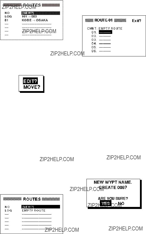
4.Select ???NEW???? and press the [ENT] key. The screen shown in Figure
Figure
8.The LOG field shows the first and last waypoints entered for the log route you are currently creating. Select the LOG field and press the [ENT] key. The EDIT/ MOVE window appears.
Figure
9.Select ???MOVE???? and press the [ENT] key. The route is moved from the LOG field and is registered under the next se- quential route number.
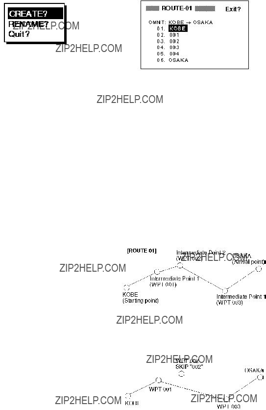
Creating a route with preregistered waypoints from the route menu
The procedure which follows describes how to create a route from two preregistered waypoints, KOBE and OSAKA, on the ROUTE screen.
1.Press the [MENU] key once or twice to display the menu.
2.Select ROUTES.
3.Press the [ENT] key. The screen shown in Figure
Figure
5.Press ??? and the [ENT] key to change route name, if desired. (If no name is entered the name of the first and last waypoints in the route will become the route name, although you may change the name at a later time.) Enter route name and press the [ENT] key.The cur- sor is on line 01 and press the [ENT] key.
6.Press [ENT] key and press ??? or ??? to display waypoint name. (In the example, KOBE.)
7.Press the [ENT] key. The cursor moves to the next line.
8.Repeat steps 6 and 7 until you have en- tered all waypoints desired.
Note: If you enter a waypoint which has not been registered, the display will look something like the one below. Select YES to create a new waypoint; NO to return to the route entry screen.
4.Select a waypoint and press the [ENT] key. Your screen should look something like the one in Figure
Figure
9. Select ???Exit?.???
10.Press the [ENT] key to register the route.
Then, ROUTES list shows the name of the first and last waypoints, next to route number.
Figure
11.Press the [MENU] key twice to finish.
Figure
5.Select ???LOG RT???? and press the [ENT] key.
6.Repeat steps 4 and 5 to complete the route.
7.Press the [MENU] key once.
8.Select ROUTES and press the [ENT] key. Your screen should now look some- thing like the one shown in Figure
Creating a route with preregistered waypoints from the waypoint list
1.Press the [MENU] key once or twice to display the menu.
2.Select WAYPOINTS and press the [ENT] key.
3.Select LIST or NEAREST and press the [ENT] key.
Figure
Figure
9.Select the LOG field and press the [ENT] key. The EDIT/MOVE window appears.
Figure
10.Select ???MOVE???? and press the [ENT] key. The route is moved from the LOG field and assigned the next sequential route number.

Creating a
This method stores current position at ap- propriate intervals. It is useful for retracing previous ship???s track.
1. Press the [MARK/MOB] key.
Note: You can create a route using a com- bination of current positions and waypoint positions (including cursor position). The route can be started from a waypoint posi- tion or current position. The former method allows you to select the route name before- hand.
Figure
2.Change name, comment, mark shape if desired. Select ???LOG RT???? and press the [ENT] key.
3.Repeat steps 1 and 2 at appropriate in- tervals.
4.When you have entered all the waypoint positions desired, press the [MENU] key twice, select ROUTES and press the [ENT] key.
4.2 Editing Routes
Replacing waypoints in a route
1.Press the [MENU] key once or twice to display the menu.
2.Select ROUTES and press the [ENT] key.
3.Select the route to edit.
4.Press the [ENT] key.
5.Place the cursor on the waypoint to re- place.
6.Press the [ENT] key. The following win- dow appears.
Figure
5.Select the LOG field and press the [ENT] key. The EDIT/MOVE window appears.
Figure
6.Select ???MOVE???? and press the [ENT] key. The route is moved from the LOG field and is registered under the next se- quential route number.
Figure
7.???CHANGE????is selected; press the [ENT] key.
Figure
8.Press the [ENT] key. Use the cursor pad to select waypoint.
9.Press the [ENT] key.
Note: If the name selected at step 8 has not been used, the window shown in Figure
5.Select the waypoint which will come af- ter the waypoint to be inserted. In Fig- ure
Figure
10.Select ???Exit?.???
11.Press the [ENT] key.
12.Press the [MENU] key twice to finish.
Permanently deleting a waypoint from a route
1.Press the [MENU] key or twice to dis- play the menu.
2.Select ROUTES and press the [ENT] key.
3.Select the route from the ROUTES list.
4.Press the [ENT] key.
5.Select the waypoint you want to delete.
6.Press the [ENT] key.
7.Select ???REMOVE?.???
8.Press the [ENT] key.
9.Press the [MENU] key twice to finish.
Inserting a waypoint in a route
To insert a waypoint in a route, do the fol- lowing:
1.Press the [MENU] key once or twice to display the menu.
2.Select ROUTES and press the [ENT] key.
3.Select the route from the ROUTES list.
4.Press the [ENT] key.
Figure
6.Press the [ENT] key.
7.Select ???INSERT?.???
8.Press the [ENT] key.
9.Use the cursor pad to select waypoint. 10.Press the [ENT] key.
11.Press the [MENU] key twice to finish.
Temporarily deselecting a waypoint in a route
You can temporarily deselect an unneces- sary waypoint from a route. Using the route created in Figure
Figure
If you reconstruct the route without the 2nd intermediate point it would look like Figure
Figure
1.Press the [MENU] key once or twice to display the menu.
2.Select ROUTES and press the [ENT] key.
3.Select a route from the ROUTES list, and press the [ENT] key.
4.Place the cursor on the waypoint to skip.
5.Press the [ENT] key.
6.Select ???SKIP???? and press the [ENT] key. X appears to the left of the waypoint.
Figure
7. Press the [MENU] key twice to finish.
To restore a waypoint to a route, select ???SKPoFF ????at step 6 and press the [ENT] key.
Changing route comment (name)
When a waypoint- or
1.Press the [MENU] key or twice to dis- play the menu.
2.Select ROUTES and press the [ENT] key.
3.Select route number and press the [ENT] key.
4.Select the CMNT field and press the
[ENT] key.
5.Enter comment with the cursor pad and press the [ENT] key.
6.Press the [MENU] key twice to finish.
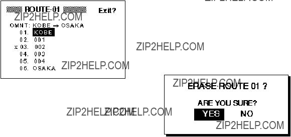
4.3 Deleting a Route
1.Press the [MENU] key or twice to dis- play the menu.
2.Select ERASE and press the [ENT] key.
3.Select ???ROUTES???? and press the [ENT] key.
4.Select the route you want delete. If you want to delete all routes, select ???ALL?.???
5.Press the [ENT] key. You are asked if you are sure to delete the route.
Figure
6.Press the [ENT] key again.
7.Press the [MENU] key twice to finish.

5. NAVIGATION
Destination can be set four ways: by cur- sor, by waypoint, by route, and by MOB po- sition. Previous destination is cancelled whenever a destination is newly set.
5.1Setting Destination by Cursor
1.Press the [GOTO] key to display the GOTO window.
 GOTO
GOTO 
ROUTE?
CURSOR?
OFF?
Figure
2.Select ???CURSOR?.???
3.Press the [ENT] key. The plotter display appears with ??????? shown to the right of the cursor.
Cursor appears with "?".
+GOTO?
BRG: +
72??
RNG: +
54.5mn
34?? 44.000N 135?? 21.000E
Figure
4.Place the cursor on the location desired for destination.
5. Press the [ENT] key.
A dashed line connects own ship and the destination, which is marked with CURSOR and an X, as shown in Figure
CURSOR
x
Figure
5.2Setting Destination by Waypoint
1.Press the [GOTO] key.
2.Select
3.Press the [ENT] key. The SELECT GOTO WYPT list appears.

 SELECT GOTO WYPT


 SELECT GOTO WYPT

Figure

4.Select a waypoint.
5.Press the [ENT] key.
Own ship???s position becomes starting point and a dashed line runs between it and the waypoint selected, which is shown in re- verse video.
5.3Setting Route as Destination
1.Press the [GOTO] key.
2.Select ROUTE?.
3.Press the [ENT] key.

 SELECT GOTO ROUTE

Figure
4.Select a route.
5.Press the [ENT] key. The following win- dow appears.
[ROUTE 01] Intermediate Point 2 OSAKA
KOBE
(Starting point)Intermediate Point 1 (WPT 003)
Figure
Current position becomes the starting point. A dotted line runs between the starting point and all route waypoints. Next destination waypoint is shown in reverse video. The destination waypoint is automatically switched when the boat enters the arrival alarm range or the boat passes an imagi- nary perpendicular line passing through the center of the destination waypoint. For how to set the arrival alarm, see page
WPT 2
Waypoint switched at this point.
WPT 1
Perpendicular
FORWARD?
REVERSE?
Figure
prompt
6.Select ???FORWARD???? or ???REVERSE????, the order in which to traverse the route waypoints, and press the [ENT] key.
WPT 2
Waypoint switched at this point.
WPT 1
Arrival Alarm Circle
5.4 Canceling Destination
You can cancel destination as follows:
1.Press the [GOTO] key.
2.Select OFF?.
3.Press the [ENT] key.
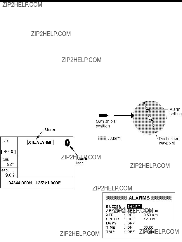
6. ALARMS
There are seven alarm conditions which generate both aural and visual alarms: Ar- rival alarm, Anchor watch alarm, XTE
When an alarm setting is violated, the buzzer sounds, and the name of the offend- ing alarm and the alarm icon appear on the display. You can silence the buzzer and remove the alarm name indication by press- ing any key; the alarm icon remains on the screen until the reason for the alarm is cleared.
You can see which alarm(s) is sounding by displaying the message board by the fol- lowing keying sequence: [MENU] (once or twice) MESSAGE, [ENT]. The message board is discussed in paragraph 8.2 ???Dis- playing the Message Board.???
6.1Arrival Alarm, Anchor Watch Alarm
You may activate the arrival alarm or the anchor watch alarm; they cannot be acti- vated together.
Arrival alarm
The arrival alarm informs you that own ship is approaching a destination waypoint. The area that defines an arrival zone is that of a circle which you approach from the out- side of the circle. The alarm will be released if own ship enters the circle.
Figure
1.Press the [MENU] key once or twice to open the menu.
2.Select ALARMS.
3.Press the [ENT] key. The ALARMS menu appears.
Figure
Figure
4.If ARV is not selected from the ARV/ANC field, select the ARV/ANC field and press the [ENT] key. The display shown in Fig- ure  .)
.)
Figure
5.Press the [ENT] key. Enter the alarm range
6.Press the [ENT] key.
7.Press the [MENU] key twice to finish.
When own ship nears the GOTO waypoint by the range set here, the buzzer sounds and the message ARV ALARM! and the alarm icon appear. To disable the alarm, se- lect OFF at step 4.
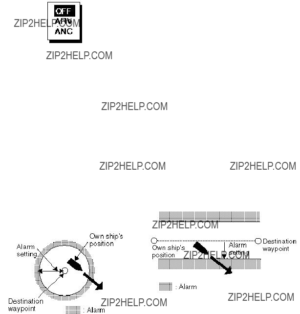
Anchor watch alarm
The anchor watch alarm sounds to warn you that own ship is moving when it should be at rest.
Figure
Before setting the anchor watch alarm, set current position as destination waypoint.
1.Press the [MENU] key once or twice to open the menu.
2.Select ALARMS.
3.Press the [ENT] key.
4.If ANC is not selected from the ARV/ANC field, select the ARV/ANC field and press the [ENT] key. The display shown in Fig- ure  .)
.)
5.Press the [ENT] key. Enter the alarm range
6.Press the [ENT] key.
7.Press the [MENU] key twice to finish.
When own ship drifts more than the range set here, the buzzer sounds and the mes- sage ANC ALARM! and the alarm icon ap- pear. To disable the alarm, select OFF at step 4.
6.2XTE (Cross Track Error) Alarm
The XTE alarm warns you when own ship is off its intended course.
Figure
1.Press the [MENU] key once or twice to open the menu.
2.Select ALARMS.
3.Press the [ENT] key.
4.Select the XTE field and press the [ENT] key.
5.Select ON or OFF as appropriate and press the [ENT] key.
6.For ON, press the [ENT] key again.
7.Enter alarm range (range:
8.Press the [ENT] key.
9.Press the [MENU] key twice to finish.
When own ship strays from the intended track by the range set here, the buzzer sounds and message XTE ERROR! and the alarm icon appear. To disable the alarm, select OFF at step 5.
6.3 Speed Alarm
The speed alarm sounds when ship???s speed is higher (or lower) the alarm range set.
1.Press the [MENU] key once or twice to open the menu.
2.Select ALARMS.
3.Press the [ENT] key.
4.Select the SPEED field and press the [ENT] key.
5.Select OFF, LO or HI as appropriate.
OFF: Disables the speed alarm.
LO: Alarm sounds when speed is lower than speed set.
HI: Alarm sounds when speed is higher than speed set.
6.For LO or HI, Press the [ENT] key twice.
7.Enter speed (range:
8.Press the [ENT] key.
9.Press the [MENU] key twice to finish.
When the speed alarm setting is violated, the buzzer sounds and the message SPD ALARM! and the alarm icon appear. To dis- able the alarm, select OFF at step 5.
6.4 DGPS Alarm
This alarm alerts you by aural and visual alarms when the DGPS beacon signal is lost.
1.Press the [MENU] key once or twice to open the menu.
2.Select ALARMS.
3.Press the [ENT] key.
4.Select the DGPS field and press the [ENT] key.
5.Select ON or OFF as appropriate.
6.Press the [ENT] key.
7.Press the [MENU] key twice to finish.
When the DGPS alarm setting is violated, the buzzer sounds and the message DGPS ALARM! and the alarm icon appear. To dis- able the DGPS alarm select OFF at step 5.
6.5 Time Alarm
This alarm alerts you by aural and visual alarms when the time entered has come.
1.Press the [MENU] key once or twice to open the menu.
2.Select ALARMS.
3.Press the [ENT] key.
4.Select the TIME field and press the [ENT] key.
5.Select ON or OFF as appropriate and press the [ENT] key.
6.For ON, press the [ENT] key again.
7.Enter time desired with the cursor pad.
8.Press the [ENT] key.
9.Press the [MENU] key twice to finish.
When the time entered has come, the buzzer sounds and the message TIME ALARM! and the alarm icon appear. To dis- able the timer alarm select OFF at step 5.

6.6 Trip Distance Alarm
This alarm alerts you by aural and visual alarms when your boat has traveled a greater distance than the preset trip alarm distance.
1.Press the [MENU] key once or twice to open the menu.
2.Select ALARMS.
3.Press the [ENT] key.
4.Select the TRIP field and press the [ENT] key.
5.Select ON or OFF as appropriate and press the [ENT] key.
6.For ON, press the [ENT] key again.
7.Enter distance desired (range:
8.Press the [ENT] key.
9.Press the [MENU] key twice to finish.
When the boat has traveled further than the preset trip distance, the buzzer sounds and the message TRIP ALARM! and the alarm icon appear. To disable the trip alarm se- lect OFF at step 5.
6.7 Buzzer Type Selection
The buzzer sounds whenever an alarm setting is violated. You can select the type of buzzer to use as follows:
1.Press the [MENU] key once or twice to open the menu.
2.Select ALARMS.
3.Press the [ENT] key.
4.Select the BUZZER field and press the [ENT] key. The following display ap- pears.
Figure
5.Select buzzer type desired and press the [ENT] key.
SHORT: Two short beeps
LONG: Three long beeps
CONSTANT: Continuous beeps
6. Press the [MENU] key twice to finish.
7. OTHER FUNCTIONS
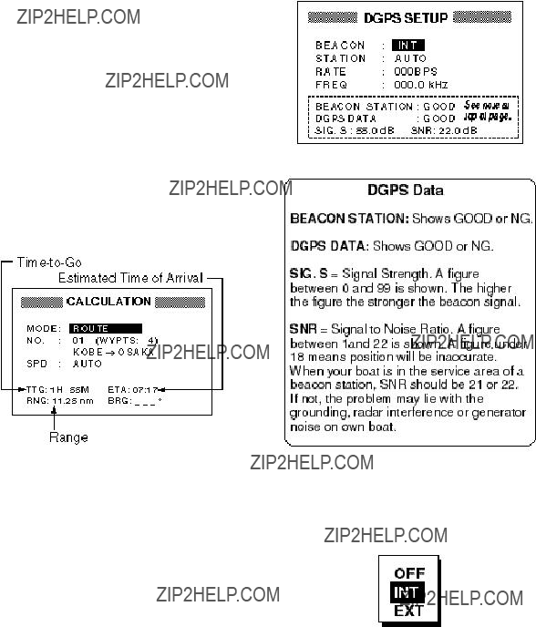
7.1Calculating Range, Bearing and TTG
Range and bearing between two waypoints
1.Press the [MENU] key once or twice to open the menu.
2.Select CALCULATE.
3.Press the [ENT] key.
Figure
4.Press the [ENT] key to display the win- dow shown in Figure
Figure
5.Select WAYPOINTS and press the [ENT] key.
6.Press the [ENT] key.
7.Enter the FROM waypoint and press the [ENT] key.
8.Press the [ENT] key, enter the TO waypoint and press the [ENT] key.
9.Press the [ENT] key. The window shown in Figure
Figure
10.Select AUTO or MANU. AUTO uses ship???s average speed; MANU is for manual entry of speed.
11.Press the [ENT] key.
12.If you selected MANU, press the [ENT] key again. Enter speed with the cursor pad and press the [ENT] key.
Figure
Figure
13.Press the [MENU] key twice to finish.
Range, TTG, ETA between first and final waypoints of a route
You can easily find the range, TTG and ETA between the first and final waypoints of a route as follows:
1.Press the [MENU] key once or twice to open the menu.
2.Select CALCULATE and press the [ENT] key.
3.Press the [ENT] key.
4.Select ROUTE and press the [ENT] key.
5.Press the [ENT] key.
6.Select route number from the route list with the cursor pad.
7.Press the [ENT] key to display the win- dow shown in Figure
8.Select AUTO or MANU. AUTO uses ship???s average speed to calculate time-
9.Press the [ENT] key. If you selected AUTO no further operation is necessary. For MANU, press the [ENT] key again. Enter speed with the cursor pad and press the [ENT] key.
Figure
Figure
7.2 DGPS Setup, DGPS Data
The
1.Press the [MENU] key once or twice to open the menu.
2.Select
Figure
3.The cursor is on the BEACON field. Press the [ENT] key.
4.A window showing the choices INT, EXT and OFF appears. Select one of those items and press the [ENT] key.
Figure
INT: For internal DGPS beacon receiver
EXT: For external DGPS beacon receiver
OFF: Disables DGPS function. When the DGPS function turns off,it takes about 1 minute to fix GPS position.
Note: When connecting a FURUNO external DGPS beacon receiver (such as
5.The cursor is on the STATION field. Press the [ENT] key.
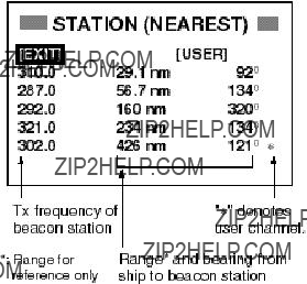
6.Choose DGPS beacon station selection method: AUTO, MANUAL or LIST.
AUTO: Automatically searches for best of five nearest DGPS beacon station. It first searches DGPS beacon stations from closest to furthest. If unsuccessful it searches stations by signal strength. This procedure is repeated until a suitable station is found.
MANUAL: Manually enter DGPS beacon station specifications in the RATE and FREQ fields, referring to a DGPS beacon station list.
LIST: Lists 5 of the closest DGPS beacon stations, including
7.Press the [ENT] key. If you selected AUTO no further operation is required; press the [ENT] key to finish. For MANUAL or LIST do one of the follow- ing:
MANUAL
a)The cursor is now on the RATE field. Press the [ENT] key.
b)Select the transmission rate of the DGPS beacon station to be used, among 50, 100 or 200 bps. Press the [ENT] key.
c)The cursor is now on the FREQ field. Press the [ENT] key.
d)Enter the transmission frequency of the DGPS beacon station to be used and press the [ENT] key.
LIST
a)The following display appears after pressing the [ENT] key at step 7.
Figure
b)Select desired station with the Cursor Pad.
c)Press the [ENT] key.
11.Press the [MENU] key twice to finish. Note that the STATION field in the DGPS menu now shows MANUAL.
Programming user channels (stations)
The user may program 20 DGPS beacon stations from which to use in DGPS bea- con station selection. Whenever a new sta- tion is constructed you include it in the list.
1.Press the [MENU] key twice to open the menu.
2.Select DGPS and press the [ENT] key.
3.Select STATION and press the [ENT] key.
4.Select LIST and press the [ENT] key. The display shown in Figure
5.Select USER and press the [ENT] key. The following display appears.
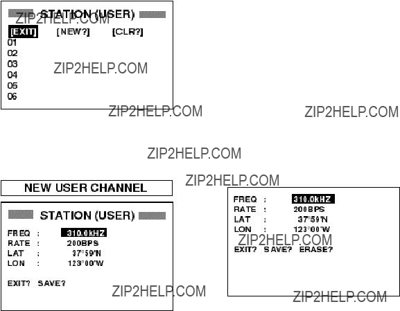
Figure
6.Select ???NEW???? and press the [ENT] key. The following display appears.
Figure
CHANNEL display
7.Press the [ENT] key, enter frequency of the station, and press the [ENT] key.
8.Press the [ENT] key, enter baud rate of the station, and press the [ENT] key.
9.Press the [ENT] key, enter latitude of the station, and press the [ENT] key.
10 Press the [ENT] key, enter longitude of the station, and press the [ENT] key.
11.Select ???SAVE???? and press the [ENT] key.
12.Press the [MENU] key twice to finish.
Editing user channels
1.Press the [MENU] key twice to open the menu.
2.Select DGPS and press the [ENT] key.
3.Select STATION and press the [ENT] key.
4.Select LIST and press the [ENT] key.
5.Select USER and press the [ENT] key.
6.Select a station from the list and press the [ENT] key. The display looks some- thing like the one below.
Figure
7.Select item, press the [ENT] key, edit data, and press the [ENT] key.
8.Select ???SAVE???? and press the [ENT] key.
9.Press the [MENU] key twice to finish.
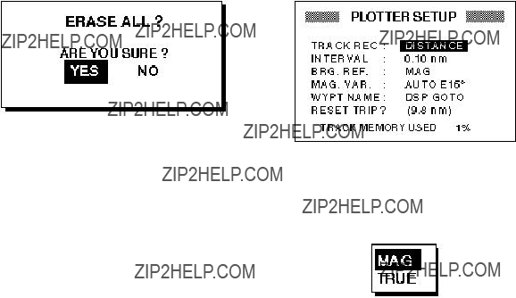
Erasing all user channels
1.Press the [MENU] key twice to open the menu.
2.Select DGPS and press the [ENT] key.
3.Select STATION and press the [ENT] key.
4.Select LIST and press the [ENT] key.
5.Select USER and press the [ENT] key.
6.Select CLR? and press the [ENT] key. The following message appears.
Figure
7.Press the [ENT] key to erase all user channels.
Erasing individual user channels
1.Press the [MENU] key twice to open the menu.
2.Select
3.Select STATION and press the [ENT] key.
4.Select LIST and press the [ENT] key.
5.Select USER and press the [ENT] key.
6.Select a channel from the list and press the [ENT] key.
7.Select ???ERASE????.
8.Press the [ENT] key to erase channel selected.
7.3 Bearing Reference
Ship's course and bearing to a waypoint may be displayed in true or magnetic bear- ing. Magnetic bearing is true bearing plus
(or minus) earth???s magnetic deviation. Use the bearing reference according to com- pass interfaced: magnetic for magnetic compass, true for gyrocompass.
The default setting displays magnetic bear- ings.
1.Press the [MENU] key once or twice to open the menu.
2.Select PLOTTER.
3.Press the [ENT] key.
Figure
4.Select the BRG. REF. field.
5.Press the [ENT] key. The following win- dow appears.
Figure
6.Select MAG or TRUE.
7.Press the [ENT] key.
8.Press the [MENU] key twice to finish.
7.4 Magnetic Variation
The location of the magnetic north pole is different from the geographical north pole. This causes a difference between the true and magnetic north direction. This differ- ence is called magnetic variation, and var- ies with respect to the observation point on earth. Your unit is preprogrammed with all the earth's magnetic variation. However, you may wish to enter variation manually to refine accuracy. When the option MAG is selected on the item BRG REF., use magnetic variation.
1.Press the [MENU] key once or twice to open the menu.
2.Select PLOTTER and press the [ENT] key.
3.Select the MAG. VAR. field.
4.Press the [ENT] key.

5.Select AUTO or MANU and press the [ENT] key. For automatic magnetic variation, current magnetic variation appears to the right of AUTO.
6.If you selected AUTO, no further opera- tion is necessary; press the [MENU] key twice to finish. For MANU, press the [ENT] key and enter magnetic variation as follows:
a)If necessary, change coordinate from east to west or vice versa by press- ing ??? or ???.
b)Enter variation in two digits with the cursor pad, referring to a nautical chart.
c)Press the [ENT] key.
d)Press the [MENU] key twice to fin- ish.
7.5 Geodetic Chart System
Your unit is preprogrammed to recognize most of the major chart systems of the world. Although the
1.Press the [MENU] key once or twice to open the menu.
2.Select SYS SETUP and press the [ENT] key.
Figure
3.Press the [ENT] key.
4.Select WGS84, (GPS standard) WGS72 or OTHER as appropriate and press the [ENT] key.
5.If you selected WGS72 or WGS84, press the [MENU] key twice to finish. For OTHER, do the following:
a)Press the [ENT] key.
b)Select chart number referring to the geodetic chart list on page
c)Press the [ENT] key.
d)Press the [MENU] key twice to fin- ish.
7.6 Units of Measurement
Distance/speed can be displayed in nauti- cal miles/knots, kilometers/kilometers per hour, or miles/miles per hour.
1.Press the [MENU] key once or twice to open the menu.
2.Select SYS SETUP and press the [ENT] key.
3.Select UNITS.
4.Press the [ENT] key.
5.Choose combination desired; nm, kt; nm, km/h; mi, mi/h.
6.Press the [ENT] key.
7.Press the [MENU] key twice to finish.
7.7 Position Display Format
Position may shown in Lat./Long., TDs (Lo- ran C or Decca) as follows. Decca and Lo- ran C chain data is preprogrammed.
1.Press the [MENU] key once or twice to open the menu.
2.Select TD SETUP and press the [ENT] key.
Figure

3.The cursor is on the first line. Press the [ENT] key. The following window ap- pears.
XX.XXX'
XX'XX.X"
LC TD
DE TD
Figure
DE TD selection window
4.Select XX.XXX???, XX???XX.X???, LC TD (Lo- ran C) or DE TD (Decca).
XX.XXX???: Shows position with no sec- onds.
XX???XX.X???: Displays position with sec- onds.
5.Press the [ENT] key. If you selected lati- tude and longitude go to step 7.
6.For Loran C or Decca, do one of the fol- lowing:
For Loran C TD;
a)The cursor is on the LORAN C field.
Press the [ENT] key.
b)Use the cursor pad to choose GRI code and secondary codes, referring to the Loran C chain list on page
c)Press the [ENT] key.
d)If necessary enter TD offsets in ap- propriate TD field(s) to refine position accuracy.
For Decca TD;
a)Select the DECCA field and press the
[ENT] key.
b)Use the cursor pad to choose Decca chain number and lane pair (R, Red,
G, Green, P, Purple), referring to the
Decca chain list on page
c)Press the [ENT] key.
d)If necessary enter TD offsets in ap- propriate TD field(s) to refine position accuracy.
7.Press the [MENU] key twice to finish.
7.8Time Difference (using local time)
GPS uses UTC time. If you would rather use local time, enter the time difference (range:
1.Press the [MENU] key once or twice to open the menu.
2.Select SYS SETUP and press the [ENT] key.
3.Press ??? to select the TIME DIFF field and press the [ENT] key.
4.Press ??? or ??? to display + or
5.Enter time difference with the cursor pad.
6.Press the [ENT] key.
7.Press the [MENU] key twice to finish.
7.9 GPS Setup
The GPS SETUP menu smooths position and course, averages speed, applies posi- tion offset, and deactivates unhealthy sat- ellites.
1.Press the [MENU] key once or twice to open the menu.
2.Select GPS SETUP and press the [ENT] key.
 GPS SETUP
Figure
3.Select item and press the [ENT] key.
4.Change setting with the cursor pad and press the [ENT] key.
5.Press the [MENU] key twice to finish.
GPS SETUP menu description
SMOOTH POS (Smoothing position)
When the DOP (Dilution of Precision, the index for
SMOOTH S/C (Smoothing speed/ course)
During position fixing, ship???s velocity (speed and course) is directly measured by receiv- ing GPS satellite signals. The raw velocity data may changes randomly depending on receiving conditions and other factors. You can reduce this random variation by in- creasing the smoothing. Like with latitude and longitude smoothing, the higher the speed and course smoothing the more smoothed the raw data. If the setting is too high, however, the response to speed and course change slows. The setting range is from 0 (no smoothing) to 999 seconds.
AVR. SPEED (Speed averaging)
Calculation of ETA and TTG, etc. is based on average ship's speed over a given pe- riod. If the period is too long or too short calculation error will result. Change this setting if calculation error occurs. The de- fault setting is one minute. The setting range is from 0 (no averaging) to 99 minutes.
LAT/LON OFFSET (L/L position offset)
You may apply an offset to latitude and lon- gitude position generated by the GPS re- ceiver, to increase position accuracy.
DISABLE SV (Disable satellite)
Every GPS satellite is broadcasting abnor- mal satellite number(s) in its Almanac, which contains general orbital data about all GPS satellites. Using this information, the GPS receiver automatically eliminates any malfunctioning satellite from the GPS satellite schedule. However, the Almanac sometimes may not contain this informa- tion. You can disable an inoperative satel- lite manually. Enter satellite number in two digits and press the [ENT] key. To restore a satellite enter ???00???.
FIX MODE
Selects position fixing method; 2D or 2/3D. 2D requires three satellites in view of the GPS receiver; 2/3D requires three or four satellites in view of the GPS receiver, which- ever is available. When the 2D mode is selected, enter the antenna height above the waterline, to obtain accurate position data. The default setting is 5 m. The table provides common feet equivalents.
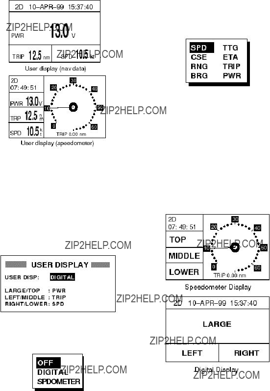
7.10 User Display Setup
The user display, which appears when the [DISP] key is pressed several times, may be either digital data (default display) or the speedometer display.
4.Select OFF (no user display), DIGITAL or SPDOMETER as appropriate and press the [ENT] key.
5.The cursor is now on the LARGE/TOP field. LARGE means the center indica- tion on the digital display; TOP is the indication below receiver status and time on the speedometer display. Press the [ENT] key. The following display ap- pears.
Figure
The user may choose three items of navi- gation data to display on each user display. The default items are battery power, speed and course.
1.Press the [MENU] key once or twice to open the menu.
2.Select USER DISP and press the [ENT] key. The following display appears.
Figure
6.Select item desired to display and press the [ENT] key. (SPD: Speed, TTG: Time-
7.Select the items LEFT/MIDDLE and RIGHT/LOWER and set their options like you did for LARGE/TOP, referring to Figure
Figure
3.Press the [ENT] key. The following dis- play appears.
Figure
Figure
9. Press the [MENU] key twice to finish.
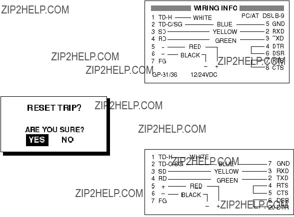
7.11 Resetting Trip Distance
1.Press the [MENU] key once or twice to open the menu.
2.Select PLOTTER and press the [ENT] key.
3.Select the RESET TRIP? field and press the [ENT] key. The following display appears.
Figure
4.Press the [ENT] key to reset trip dis- tance.
5.Press the [MENU] key twice to finish.
7.12 Uploading, Downloading
Waypoint, Route Data
Waypoint and route data may be down- loaded to a PC or uploaded from a PC to your unit.
Wiring
Your equipment provides a wiring diagram which shows how to connect to a PC using a DSUB
1.Press the [MENU] key once or twice to open the menu.
2.Select I/O SETUP and press the [ENT] key.
3.Select WIRING INFO and press the [ENT] key to display the wiring diagram
Figure
A DSUB
Figure
Setting for communication software on PC
Downloading/Uploading between PC and
The following data can be downloaded/up- loaded between a personal computer and the
???Waypoint data (In alphanumerical order)
???Route data ( In order of route number)
Note 1: There are two kinds of data for route
data: route data and route comment data.
Note 2: DPGS position fix is not available when uploading or downloading data.
Downloading data to a PC
1.Press the [MENU] key once or twice to open the menu, select I/O SETUP and press the [ENT] key.
Figure
2.Select SAVE WP/RTE ??? PC?.
3.Press the [ENT] key.
Figure
4. Press the [ENT] key.
Figure
5.Setup the computer to receive data.
6.Press the [ENT] key.
Figure
7. Press any key to escape.
Uploading data from a PC
Note that all waypoint and route data stored in
1.Press the [MENU] key once or twice to open the menu, select I/O SETUP and press the [ENT] key.
2.Select LOAD WP/RTE ??? PC?.
3.Press the [ENT] key.
Figure
4. Press the [ENT] key.
Figure
5. Set up the computer to output data.
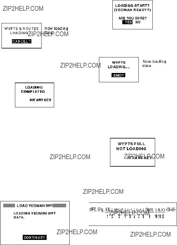
6. Press the [ENT] key.
Note: The waypoint and route data are deleted when the [ENT] key is pressed.
Figure
7.When the loading is completed, the fol- lowing message appears.
Figure
8. Press any key to escape.
Loading data from a YEOMAN
Waypoint data from a YEOMAN has the same format as does the NMEA 0183 data sentences WPL.
1.Press the [MENU] key twice, select I/O SETUP and press the [ENT] key.
2.Select LOAD WP ??? YEOMAN?.
3.Press the [ENT] key.
Figure
4. Press the [ENT] key.
Figure
5.Set up the YEOMAN to output data.
6.Press the [ENT] key.
Figure
7.Press the [ENT] key to start the load- ing. Data is loaded to empty location and the buzzer sounds twice to signify suc- cessful loading. If there is not enough memory free to store the waypoints the message below appears.
Figure
Waypoint data format
Figure
1: Waypoint latitude
2: N/S
3: Waypoint longitude
4: E/W
5: Waypoint name (Number of characters is fixed to 6 and space code is placed

when the number of characters are less than 6.)
6: Waypoint color (This field is always kept NULL.)
7: Waypoint comment (2 byte for mark code + 16 characters of comment.)
1st byte of mark code: Fixed to '@'. 2nd byte of mark code:Internal mark code + 'a' (0 x 61). See Note 1. Number of characters for comment is less than 16 (variable length). See Note 2.
8: Flag making waypoint. Always set to ???A???.
???A???: Displayed
???V???: Not displayed
9: UTC (Always NULL)
10: Day (Always NULL)
11: Month (Always NULL)
12: Year (Always NULL)
Note 1: Internal mark code is 0 x 10 through 0 x 18. 0 x 71 through 0 x 79 are always placed at 2nd byte of mark code.
Note 2: Following characters can be used for comments:
Figure
Route data format
Figure
1: Number of sentences required for one complete route data (1 to 4). See Note.
2: Number of sentences currently used (1 to 4)
3: Message mode (Always set to C).
4: Route No. (01 to 51 (51 is LOG route, 2 digits required)
5 through 12: Waypoint name (Max. 8 names, length of each waypoint name is fixed to 7 byte)
1st byte: Skip code
After 2nd byte: Waypoint name (fixed to 6 bytes)
Note: A route can contain max. 30 waypoints and GPRTE sentence for one route data may exceed 80 byte limitation. In this case, route data is divided into sev- eral GPRTE sentences (Max. 4 sentences). This value shows the number of sentences route data has been divided.
Route comment data format
Figure
1: Route No. (01 to 51, 2 digits required)
2: Route comment (Max. 16 characters, variable length)
The same characters of the comment for waypoint comment can be used.
End of sentence
Figure
7.13 Time Display
You may display the time in
1.Press the [MENU] key once or twice to open the menu.
2.Select SYS SETUP and press the [ENT] key.
3.Select TIME DISP and press the [ENT] key.
4.Select 12HOUR or 24HOUR as appro- priate.
5.Press the [ENT] key followed by the [MENU] key.
8.MAINTENANCE & TROUBLESHOOTING
3.Press the [ENT] key.
8.1 Maintenance
Check the following points regularly to maintain performance:
???Check that connectors on the rear panel are firmly tightened and free of rust.
???Check that the ground system is free of rust and the ground wire is tightly fas- tened.
???Check that battery terminals are clean and free of rust.
???Check the antenna for damage. Replace if damaged.
???Dust and dirt on the keyboard and dis- play screen may be removed with a soft cloth. Do not use chemical cleaners to clean the equipment; they may remove paint and markings.
8.2Displaying the Message Board
The message board displays error mes- sages and alerts. You can display it as fol- lows:
1.Press the [MENU] key once or twice to open the menu.
2.Select MESSAGES.
Figure
4.Press the [MENU] key twice to quit the message board.
Messages
Table
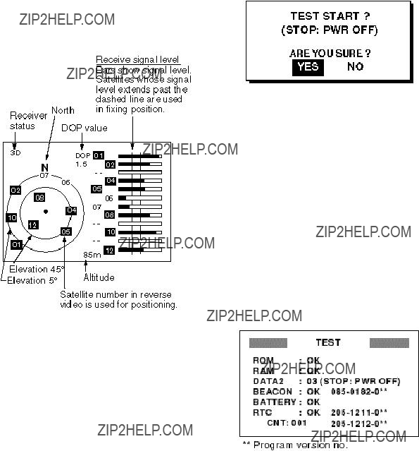
8.3Displaying the GPS Satellite Monitor Display
The GPS satellite monitor display shows information about GPS satellites.
1.Press the [MENU] key once or twice to open the menu.
2.Select SATELLITE.
3.Press the [ENT] key.
Number, bearing and elevation angle of all satellites in view of the GPS receiver appear. Satellites being used in fixing position are displayed in reverse video; satellites not being used are shown in normal video.
8.4 Diagnostic Test
The diagnostic test checks ROM, RAM, data port, beacon receiver, battery, RTC, keyboard and LCD for proper operation.
1.Press the [MENU] key once or twice to open the menu.
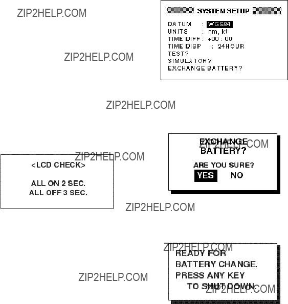
2.Select SYS SETUP and press the [ENT] key.
3.Select ???TEST???? and press the [ENT] key. You are asked if you are ready to start the test.
Figure
4.Press the [MENU] key twice to quit the SATELLITE display.
Figure
4.Press the [ENT] key to start the test.
5.The equipment tests ROM, RAM, data port, beacon receiver, internal battery and RTC. The results are individually displayed as OK or NG (No Good).
Note 1: NONE appears next to BEA- CON when no beacon receiver is con- nected to the
Note 2: DATA2 requires a special con- nector to check. 03 appears as the re- sult when no connector is connected.
Note 3: No program number shown for BEACON in case of the
Note 4: CNT is the number of times test has been consecutively executed.
Figure
6.After the equipment has checked the items shown in Figure
7.Press each key one by one. The name of the key pressed momentarily appears at the top
Note: If no key is pressed within approx. five seconds, the equipment automati- cally proceeds to step 8.
8.The equipment displays the following message to inform you that it is now go- ing to check the LCD:
Figure
9.The LCD is checked as shown in the message in Figure
8.5When ???BATTERY ALARM!??? Appears
A lithium battery (type: TZ6580553A, code
no.:
The life of the battery is about
1.Press the [MENU] key once or twice to open the menu.
2Select SYS SETUP and press the [ENT] key.
Figure
3.Select ???EXCHANGE BATTERY???? and press the [ENT] key. The display shows the following:
Figure
4.Press the [ENT] key. Then, the follow- ing display appears.
Figure
5.Press any key to automatically turn off the unit.
Then, important items in the RAM area are transferred to a temporary area in the flash memory to prevent loss of data.
Note : When it is expected that the

8.6 Clearing Data
You may clear GPS data, menu settings and all backup data to start afresh.
1.Press the [MENU] key once or twice to open the menu.
2.Select ERASE and press the [ENT] key.
3.Select GPS DATA?, MENU SETTINGS, or ALL BACKUP DATA as appropriate and press the [ENT] key. One of the fol- lowing messages appears.
Figure
4.Press the [ENT] key. The following dis- play appears.
Figure
5.Hit any key to erase item selected. A beep sounds while the selected item is being erased, and then the plotter dis- play appears.
9. INSTALLATION
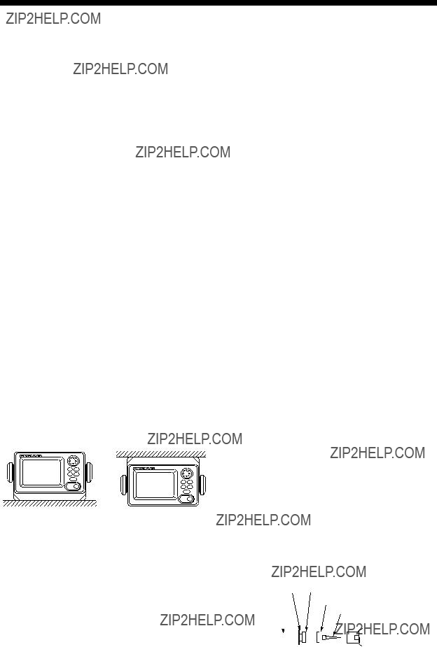
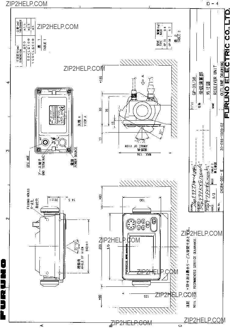
9.1 Installation of Display Unit
Mounting considerations
The display unit can be installed on a table- top, on the overhead, or in a panel (optional flush mounting kit required). Refer to the outline drawings at the end of this manual for installation instructions. When selecting a mounting location, keep in mind the fol- lowing points:
???Locate the unit away from exhaust pipes and vents.
???The mounting location should be well ventilated.
???Mount the unit where shock and vibra- tion are minimal.
???Locate the unit away from equipment which generates electromagnetic fields such as a motor or generator.
???Allow sufficient maintenance space at the sides and rear of the unit and leave sufficient slack in cables, to facilitate maintenance and servicing.
???Observe the following compass safe dis- tances to prevent deviation of a magnetic compass. Standard compass, 0.5 m, Steering compass, 0.3 m.
Tabletop and overhead mounting
Figure
Flush mounting
There are two types of flush mounting kits. For details, see the outline drawings at the end of this manual for details.
9.2 Installation of Antenna Unit
Mounting considerations
Install the antenna unit referring to the an- tenna installation diagram at the end of this manual. When selecting a mounting loca- tion for the antenna unit, keep in mind the following points:
???Do not shorten the antenna cable.
???Select a location out of the radar beam. The radar beam will obstruct or prevent reception of the GPS signal.
???The location should be well away from a VHF/UHF antenna. A GPS receiver is in- terfered by a harmonic wave of a VHF/
UHF antenna.
???There should be no interfering object within the
???Mount the antenna unit as high as pos- sible. Mounting the antenna unit as high as possible keeps it free of interfering objects and water spray, which can in- terrupt reception of GPS satellite signal if the water freezes.
???The length of the whip antenna for the
???If the antenna cable is to be passed through a hole which is not large enough to pass the connector, you may unfas- ten the connector with a needle nose pliers and
Washer Gasket (reddish brown)
Figure

9.3 Wiring
The figure below shows where to connect cables on the rear of the display unit. Please review the WARNING SHEET at the front of this manual before wiring the equipment.
ANTENNA UNIT
(Shown:
GPS ANT
DISPLAY
UNIT
POWER Ground
 CAUTION
Ground the equipment to prevent mutual interference.
Figure
Note: The fuse holder contains a spring which fixes the fuse. To prevent detachment of the spring, which would cause loss of power, tie the line as shown in Figure
Fuse holder
+ line (red)
 Tie here.
Figure
Grounding
The display unit contains a CPU. While it is operating, it radiates noise, which can in- terfere with radio equipment. Ground the unit as follows to prevent interference:
???The ground wire should be 1.25sq or larger.
???The ground wire should be as short as possible.
???The signal ground and frame ground are separated, however the power line is not isolated. Therefore, do not connect the signal ground to the frame ground when connecting other equipment to a posi- tive ground battery.
???The antenna unit
???The power of this equipment is not iso- lated, thus the earth lamp may light when the antenna unit
0.1mF) in parallel to the antenna earth line.
External equipment
The power supply port is commonly used for connection of external equipment such as navigation equipment or a PC. Refer to the interconnection diagram on page
9.4 Initial Settings
This equipment can output navigation data to external equipment, in NMEA 0183 for- mat. For example, it can output position data to a radar or echo sounder for display on its display screen.
Output data format, data sentences
NMEA 0183 version 1.5 or 2.0 can be se- lected through the menu.
DATA1: Current loop data
No Waypoint
*Output when LC TD is displayed.
RMA: Ver. 2.0 only
GTD: Ver. 1.5 only
AP: Autopilot
DATA2:
With Waypoint
*Output when LC TD is displayed.
RMA: Ver. 2.0 only
GTD: Ver. 1.5 only
DATA2
Data sentence description
AAM: Arrival alarm
APB: Autopilot data (XTE and bearing to waypoint)
BOD: Bearing from own ship to destination
BWC: Range and bearing to waypoint (great circle navigation)
GGA: GPS position fixing condition (time of fix, latitude, longitude, receiving condition, number of satellites used,
DOP)
GLL: Latitude and longitude
GTD:
RMA: Generic navigational information (latitude, longitude,
RMB: Generic navigational information
(cross track error, steering direction, starting waypoint no., destination waypoint no., latitude and longitude of starting waypoint, latitude and lon- gitude of destination waypoint, range and bearing to waypoint, range and bearing from present position to des- tination waypoint, velocity to desti- nation, arrival alarm)
RMC: Generic navigational information (UTC time, latitude, longitude, ground speed, true course, day, month, year)
VTG: Actual track and ground speeds
XTE: Course error amount and direction to steer
ZDA: UTC time (day, month, year)

Output setting
1.Press [MENU] once or twice to open the menu.
2.Operate the cursor pad to select I/O
SETUP.
3.Press the [ENT] key.
I/O SETUP
WIRING INFO?
Figure
4.To change setting, press ??? to select DATA1, DATA2 or NMEA VER as ap- propriate.
5.Press the [ENT] key. One of the follow- ing screens appears depending on the item selected at step 4.
*BEACON displayed when DGPS setting is EXT.
Figure
6. Select desired option with ??? or ???.
VER 1.5, 2.0: Select NMEA version of external equipment. If you are unsure of NMEA version no., try both and se- lect the one which successfully outputs data.
7.Press the [ENT] key.
8.Press the [MENU] key to finish.

Menu Tree
Default settings shown in boldface italic.


Loran C Chains

Decca Chains

Geodetic Chart List


INDEX
A
Alarms
anchor watch
time
Anchor watch alarm
B
Battery replacement (technicians only)
Buzzer type
C
Centering own ship's position
Control description
D
Data clear
cancelling
DGPS alarm
station (channel) editing
station (channel) erasure (individual)
Diagnostic test
Display modes
G
Geodetic chart list
GPS satellite monitor display
H
Highway display
I
Installation
L
Loran C chains
Loran C TDs
M
Magnetic bearing
Magnetic variation
Main menu
Maintenance
Menu tree
Message board
MOB mark
N
Nav data display
P
Plotter display
Position offset
Power on/off
R
Range and bearing calculation
changing route comments
deleting waypoints from
temporarily deselecting waypoints
S
Satellites disabling
GPS satellite monitor display
Smoothing
Speedometer display
T
TDs (Loran C or Decca) setup
Time difference
erasing
starting/stopping plotting
Trip distance reset
U
Units of measurement
examples
W
Waypoints deleting
entry at own ship's position
name display
X
XTE alarm
Z
Zoom in/out