MULTI DISPLAY

Nishinomiya, Japan
Telephone :
PUB.No.
( DAMI )
Your Local Agent/Dealer
FIRST EDITION : MAR. 2001
H :: MAR. 03,2004
*00080917705*
*00080917705*
* 0 0 0 8 0 9 1 7 7 0 5 *
*OME44130H00*
*OME44130H00*
* O M E 4 4 1 3 0 H 0 0 *


 SAFETY INSTRUCTIONS
 WARNING
Do not open the equipment.
Only qualified personnel should work inside the equipment.
Do not disassemble or modify the equipment.
Fire, electrical shock or serious injury can result.
Immediately turn off the power at the switchboard if the equipment is emitting smoke or fire.
Continued use of the equipment can cause fire or electrical shock. Contact a FURUNO agent for service.
Keep heater away from equipment.
A heater can melt the equipment's power cord, which can cause fire or electrical shock.
 CAUTION
Do not use the equipment for other than its intended purpose.
Improper use of the equipment can affect performance and void the warranty.
i

TABLE OF CONTENTS
ii

FOREWORD
A Word to the Owner of the
FURUNO Electric Company thanks you for purchasing the
For over 50 years FURUNO Electric Company has enjoyed an enviable reputation for quality and reliability throughout the world. This dedication to excellence is furthered by our extensive global network of agents and dealers.
Your Multi Display is designed and constructed to meet the rigorous demands of the marine environment. However, no machine can perform its intended function unless properly installed and maintained. Please carefully read and follow the operation and maintenance procedures set forth in this manual.
We would appreciate feedback from you, the
Thank you for considering and purchasing FURUNO.
Features
The
The main features of the
???Compact display unit features
???Five user programmable displays.
???Highway display provides graphic presentation of ship???s progress toward destination waypoint.
???Ten alarm functions: Arrival/anchor watch, speed, water temperature, depth,
???Offset function for refining accuracy of data.
???AIRMAR Co. depth, temperature and speed sensors available.
iii

SYSTEM CONFIGURATION
GPS RECEIVER
MULTI DISPLAY
FURUNO
IEC
: Supplied  (NMEA 0183) NAV
: Option
EQUIPMENT

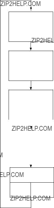
Example of single display unit connection
FURUNO
*
PWR
IEC
 (NMEA 0183)
NAV EQUIPMENT
FURUNO
*
PWR
MULTI DISPLAY
FURUNO
Note: Additonal power supply may be added to maintain minimum voltage.
IEC
: Supplied  (NMEA 0183)
NAV EQUIPMENT
: Option

Example of multiple display unit connection
iv

1.OPERATION
This chapter covers operation of the equipment, from turning on and off the equipment to how to set up the various displays.
1.1Controls
* key: Displays Rx data.
DISP key: Selects a display.
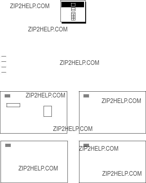
How to remove the cover
Press here and pull toward you to remove cover.

1. OPERATION
1.2Turning On/Off the Power
Turning on: Press the [PWR] switch. Release it when you hear a beep. The screen shows the
Turning off: Press the [PWR] switch. Release it when the screen becomes blank.
1.3Adjusting Key Panel Dimmer, Display Contrast
1. Press the [DIM] key to show the dimmer, contrast window.
D I M M E R ( 1 ~ 8 )
??? 

 ??? 4
??? 4
C O N T R A S T ( 0 ~ 6 3 )
4 5
E X I T : [ E N T ]
Dimmer, contrast window
2.Press ??? or ??? to adjust key panel dimmer.
3.Press ??? or ??? to adjust display contrast.
4.Press the [ENT] key to close the dimmer, contrast window.
Note: If you turn off the power with a contrast setting of less than 36, contrast is automatically set to 36 when you turn on the power again.
1. OPERATION
1.4Selecting a Display
The
Press the [DISP] key consecutively to select a display. Below is the default display sequence and default digital data items.
[DISP] key
DEPTH (FT)
210.2
[DISP] key
TEMP (?? F)
55.24
[DISP] key
SOG (KT)
10.2
DEPTH 210.2
FT
TEMP (?? F) SOG (KT)
55.24 10.2
Displays (default setting)
1. OPERATION
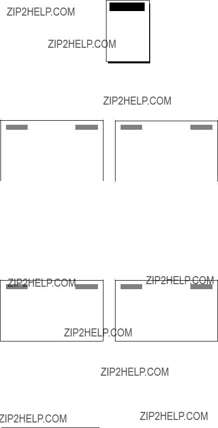
1.4.1Sample displays
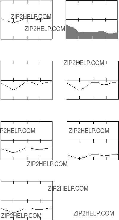
Graph displays
Water temperature, depth, speed over ground, speed through water, wind, current data and atmospheric pressure can be shown in graph form.
(5 MIN )
Speed over ground graph
(5 MIN )
Speed through water graph
Wind graph
Current graph
(120 H )
Atmospheric pressure graph
Graph displays
1. OPERATION
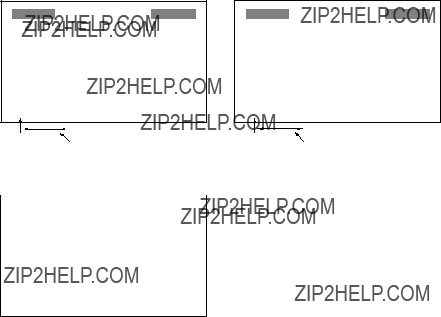
Graphic displays
The graphic display presents speed, temperature, wind, compass and current data in analog and digital formats.
SOG: SPEEDOMETER1 or
STW: SPEEDOMETER2
STW 0 9.3 KT 60
Speedometer graphic display
TEMP 0 39.10
39.10 ?? F
?? F
60
Water temperature graphic display
* = True bearing shown as "?? "; magnetic bearing as "?? M".
Compass graphic display
Current graphic display
Filled arrow indicates direction.
Graphic displays
1. OPERATION
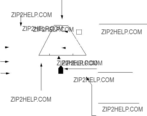
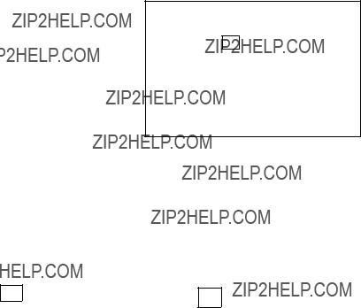
The highway display
The highway display provides a graphic presentation of ship???s progress towards a destination, together with range and bearing to the destination, and ship???s course and speed. To choose this display, select HIGHWAY from the USER DISPLAY SETUP menu, referring to the procedure on page
Destination waypoint name
Range from own ship to destination
waypointAnalog XTE
if ship's XTE is greater than the XTE scale range. "N" (North) is displayed instead of the arrow when no destination is set.
Direction to steer (flashing)
Appears on left or right side depending on direction to steer;  : Steer right,
 : Steer left.
Destination waypoint
"[+]" advances forward as own ship nears destination.
Intended course line ??? C (Delta Course)
The own ship marker displays course as follows:
When no waypoint is set; The mode is
When a waypoint is set; The own ship marker shows
ship's course towards destination.
Digital XTE indication
Highway display

1. OPERATION
Selecting the display range for the highway display
You may select the display range for the highway display among 0.2, 0.4, 0.8, 1, 2, 4, 8 and 16 nautical miles. (Nautical miles is the default range unit; kilometer and statute mile are also available. See page
1.Press the [DISP] key to show the highway display and then press the [MENU] key to show the zoom window.
ZOOM IN/OUT?
Quit?
PRESS [MENU] TO SEE
THE MAIN MENU.
Zoom window
2. Press the [ENT] key to show the zoom setting window.
ZOOM
???O U T
0 . 2 mn
???I N
E X I T : [ E N T ]
Zoom setting window
3.Press ??? or ??? to select zoom range desired. Setting range is shown in the table below.
4.Press the [ENT] key to finish.
1. OPERATION
1.5Setting up the Displays
Four display types are available: digital, graph, graphic, and highway. You may freely select and arrange what data to display in the digital, graph and graphic displays. The order in which displays are shown may also be changed. Note that the highway display cannot be adjusted.
1.5.1Choosing display type
1.Press the [MENU] key once (twice when Highway display is shown) to open the main menu.
Accessible only when heading sensor
Main menu
2. Use the cursor pad to select USER DISP and then press the [ENT] key.
USER DISPLAY SETUP 
1: DIGITAL
2: DIGITAL
3: DIGITAL
4: DIGITAL
5: DIGITAL
User display setup menu
Note:
3.Use the cursor pad to select display number desired and then press the [ENT] key.
User display options
4.Select display type among DIGITAL, GRAPH, GRAPHIC, HIGHWAY and OFF as appropriate and then press the [ENT] key.
5.For digital, graph and graphic follow one of the procedures on the next several pages to choose the data to display.
1. OPERATION
1.5.2Setting up digital displays
1.Select DIGITAL referring to paragraph 1.5.1.
2.Press the [ENT] key to show the digital display division options window.
Digital display division options window
3.Select the display division desired, that is, the number of indications to show on a digital display, and then press the [ENT] key.

 : 1 indication
 : 2 indications

 : 3 indications
  : 4 indications
4.One of the following displays appears depending on the display division type you selected at step 3.
USER DISPLAY SETUP 
A: DEPTH
B: NONE
C: NONEA
D: NONE
USER DISPLAY SETUP 
1 indication
USER DISPLAY SETUP 
2 indications
USER DISPLAY SETUP 
User display setup menus (default settings)
1.OPERATION
5.Use the cursor pad to select ???A??? and then press the [ENT] key. The data available for display is shown.
Digital display options
6.Select data desired and then press the [ENT] key. (All data require appropriate sensors.)
7.For
Note 1: A digital display shows bars
Note 2: ETA display requires the sentences ZDA and ZTG or ZTG and RMC.
8.Press the [MENU] key twice to close the menu.
1.5.3Setting up graph displays
1.Select GRAPH referring to paragraph 1.5.1.
2.Press the [ENT] key to show the graph display options window.
1. OPERATION
TEMP
DEPTH
SOG
STW
WIND
CURRENT
PRESSURE
Graph display options window
3.Choose the graph display option desired and then press the [ENT] key. One of the following graph display setup menus appears depending on your selection.
GRAPH
GRAPH
GRAPH
GRAPH
CURRENT GRAPH SETUP
Atmospheric pressure graph setup menu
Graph display setup menus
Note: The setting of PERIOD of each graph setup is linked, that is, it can not be set individually for each graph setup.

1.OPERATION
4.Use the cursor pad to select an item and then press the [ENT] key. The
To enter numeric data: Use ??? or ??? to select location and ??? or ??? to enter value and change from plus to minus and vice versa.
For
Graph setup menus
*= Every second
5.Press the [ENT] key to register setting.
6.Press the [MENU] key twice to close the menu.
TEMP (-
55
Range


 45 (5 MIN)
period (5 min.)
1. OPERATION
1.5.4Setting up graphic displays
1.Select GRAPHIC referring to paragraph 1.5.1.
2.Press the [ENT] key to show the graphic display options window.
Graphic display options window
3.Select graphic display desired and then press the [ENT] key. For water temperature, speedometer1 or speedometer2 one of the following displays appears; go to step 4. For wind, compass, current or RAI no further operation is necessary; press the [MENU] key twice to close the menu. For ROT, choose ROT max. range among 30??, 60??, 90??/min.
GRAPHIC
GRAPHIC
ROT display setup menu
Speedometer and water temperature graphic menus
4.Press the [ENT] key.
5.Use ??? or ??? to select location and ??? or ??? to enter value and switch from plus to minus and vice versa. The setting range is
6.Press the [ENT] key, and the cursor shifts to INTERVAL.
7.Press the [ENT] key.
8.Enter scale interval: Use ??? or ??? to select location and ??? or ??? to enter value. The setting range is 1 to 99.
9.Press the [ENT] key.
10.Press the [MENU] key twice to close the menu.
Note: The settings of START FROM and INTERVAL on the SPEEDOMETER and TEMPMETER SETUP are linked. Therefore they can not be set individually.

1. OPERATION
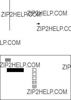
1.6Displaying Rx Data
Data currently being received can be shown by using the [*] key. Below is a sample Rx data display.
3/4
[*] Key
ODOMETER 4.33NM
TRIPMETER 2.88NM
4/4
*1 = True bearing shown as "?? "; magnetic bearing as "?? M".
*2 = True direction shown as "T"; apparent direction shown as "A".
Rx data display
1. OPERATION
1.7Alarms
The
Note: You can not turn off the no position fixing alarm nor the no position data alarm.
1.7.1Audio alarm type
Audio and visual alarms are released whenever an alarm setting is violated. You can select the audio alarm type as follows:
1.Press the [MENU] key once or twice to show the main menu.
2.Select ALARM1 and then press the [ENT] key.
ALARM1
ALARM1 menu
3. Press the [ENT] key to open the buzzer options window.
SHORT
LONG
CONTIN.
Buzzer options window
4.Use the cursor pad to select alarm type desired and then press the [ENT] key.
SHORT: Two short beeps
LONG: Three long beeps
CONTIN.: Continuous beep
5. Press the [MENU] key twice to close the menu.

1. OPERATION
1.7.2Speed alarm
The speed alarm warns when your boat???s speed is lower or higher than the speed setting, or is inside or outside of the speed range setting.
1.Press the [MENU] key once or twice to show the main menu.
2.Select ALARM1 and then press the [ENT] key.
3.Select SPEED and then press the [ENT] key to show the speed alarm options window.
OFF
LOW
HIGH
INSDE
OUTSD
Speed alarm options window
4. Select alarm type desired and then press the [ENT] key.
OFF: Turns off the speed alarm.
LOW: Alarm triggered when speed is lower than the speed setting.
HIGH: Alarm triggered when speed is higher than the speed setting.
INSDE: Alarm triggered when speed is inside the speed range setting.
OUTSD: Alarm triggered when speed is outside of the speed range setting.
5.If you turned on the alarm, press the [ENT] key and then use the cursor pad to enter the alarm setting: Use ???or ???to select location, and press ??? or ???to enter value. For INSDE and OUTSD, enter lower value on top, higher value below.
6.Press the [ENT] key.
7.Press the [MENU] key twice to close the menu.
1.7.3Water temperature alarm
The water temperature alarm warns when the water temperature is lower or higher than the temperature setting, inside or outside of the temperature range setting, or the temperature varies by the temperature set within one minute (shear).
1.Press the [MENU] key once or twice to show the main menu.
2.Select ALARM1 and then press the [ENT] key.
3.Select TEMP and then press the [ENT] key to show the water temperature alarm options window.
OFF
LOW
HIGH
INSDE
OUTSD
SHEAR
Temperature alarm options window

1. OPERATION
4. Select alarm type desired and then press the [ENT] key.
OFF: Turns off the water temperature alarm.
LOW: Alarm triggered when the water temperature is lower than the water temperature setting.
HIGH: Alarm triggered when the water temperature is higher than the water temperature setting.
INSDE: Alarm triggered when the water temperature is inside the water temperature range setting.
OUTSD: Alarm triggered when the temperature is outside of the water temperature range setting.
SHEAR: Alarm triggered when the water temperature varies more than the temperature setting within one minute.
5.If you turned on the alarm, press the [ENT] key and then use the cursor pad to enter the alarm setting: Use ??? or ??? to select location, and press ???or ???to enter value. For INSDE and OUTSD, enter lower value on top, higher value below.
6.Press the [ENT] key.
7.Press the [MENU] key twice to close the menu.
1.7.4Depth alarm
The depth alarm warns when the depth is lower or higher than the depth setting, or is inside or outside of the depth range setting.
1.Press the [MENU] key once or twice to show the main menu.
2.Select ALARM1 and then press the [ENT] key.
3.Select DEPTH and then press the [ENT] key to show the depth alarm options window.
OFF
LOW
HIGH
INSDE
OUTSD
Depth alarm options window
4. Select alarm type desired and then press the [ENT] key.
OFF: Turns off the depth alarm.
LOW: Alarm triggered when the depth is shallower than depth setting.
HIGH: Alarm triggered when the depth is deeper than depth setting.
INSDE: Alarm triggered when the depth is inside the depth range setting.
OUTSD: Alarm triggered when the depth is outside of the depth range setting.
5.If you turned on the alarm, press the [ENT] key and then use the cursor pad to enter the alarm setting: Use ??? or ??? to select location, and press ???or ???to enter value. For INSDE and OUTSD enter lower value on top, higher value below.
6.Press the [ENT] key.
7.Press the [MENU] key twice to close the menu.

1. OPERATION
1.7.5Arrival alarm, anchor watch alarm
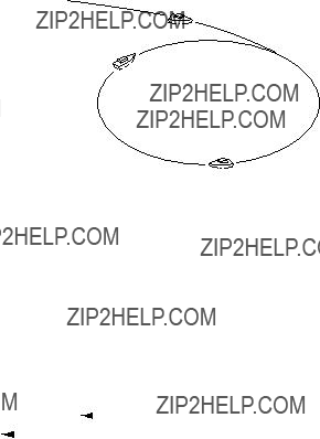
The arrival alarm informs you that your boat is approaching a destination waypoint. The area that defines an arrival zone is that of a circle which you approach from the outside of the circle. The alarm will be released if your boat enters the circle.
The anchor watch alarm informs you that your boat is moving when it should be at rest.
The arrival alarm and anchor watch alarm cannot be activated together. RMB, BWR or BWC data sentence required for these alarms.
Alarm setting
Your ship's position where you start the anchor watch alarm.
 : Alarm
area
Alarm range
Own ship
Anchor watch alarm
Arrival alarm
How the arrival alarm works
1.Press the [MENU] key once or twice to show the main menu.
2.Select ALARM2 and then press the [ENT] key.
ALARM2
ALARM2 menu
3.Select ARV/ANC and then press the [ENT] key to show the arrival alarm/anchor watch alarm options window.
OFF
ARV
ANC
Arrival/anchor watch alarm options window

1. OPERATION
5.If you turned on the alarm, press the [ENT] key and then use the cursor pad to enter the alarm setting: Use ??? or ??? to select location, and press ??? or ??? to enter value.
6.Press the [ENT] key.
7.Press the [MENU] key twice to close the menu.
1.7.6XTE (Cross Track Error) alarm
The XTE alarm, which requires the XTE data sentence, warns you when your boat is off its intended course.
 : Alarm
How the XTE alarm works
1.Press the [MENU] key once or twice to show the main menu.
2.Select ALARM2 and then press the [ENT] key.
3.Select XTE and then press the [ENT] key to show the XTE alarm options window.
4.Select OFF or ON as appropriate and then press the [ENT] key.
5.For ON, press the [ENT] key and then use the cursor pad to enter the alarm setting: Use ??? or ??? to select location, and press ??? or ??? to enter value.
6.Press the [ENT] key.
7.Press the [MENU] key twice to close the menu.
1.7.7Trip alarm
The trip alarm informs you when you have traveled a certain distance.
1.Press the [MENU] key once or twice to show the main menu.
2.Select ALARM2 and then press the [ENT] key.
3.Select TRIP and then press the [ENT] key to show the trip alarm options window.
4.Select OFF or ON as appropriate and then press the [ENT] key.
5.For ON, press the [ENT] key and then use the cursor pad to enter the alarm setting: Use ??? or ??? to select location, and press ??? or ??? to enter value.
6.Press the [ENT] key.
7.Press the [MENU] key twice to close the menu.
Note: Speed through water must be more than 0.09 kt to calculate trip distance.
1. OPERATION
1.7.8Odometer alarm
The odometer alarm informs you when your vessel has traveled the distance you have set. Its function is similar to the trip alarm except its maximum setting is 999 (nm).
1.Press the [MENU] key once or twice to show the main menu.
2.Select ALARM2 and then press the [ENT] key.
3.Select ODOMETER and then press the [ENT] key to show the odometer alarm options window.
4.Select OFF or ON as appropriate and then press the [ENT] key.
5.For ON, press the [ENT] key and then use the cursor pad to enter the alarm setting: Use ??? or ??? to select location, and press ??? or ??? to enter value.
6.Press the [ENT] key.
7.Press the [MENU] key twice to close the menu.
Note: Speed through water must be more than 0.09 kt to calculate odometer distance.
1.7.9Time alarm
The time alarm works like an alarm clock, generating visual and audio alarms when the preset time arrives. Requires ZDA or GGA data sentence.
1.Press the [MENU] key once or twice to show the main menu.
2.Select ALARM2 and then press the [ENT] key.
3.Select TIME and then press the [ENT] key to show the time alarm options window.
4.Select OFF or ON as appropriate and then press the [ENT] key.
5.For ON, press the [ENT] key and then use the cursor pad to enter the time you want for the alarm: Use ??? or ??? to select location, and press ??? or ??? to enter value.
6.Press the [ENT] key.
7.Press the [MENU] key twice to close the menu.
1.7.10Countdown alarm
The countdown alarm generates audio and visual alarms when the preset time has elapsed.
1.Press the [MENU] key once or twice to display the main menu.
2.Select ALARM2 and then press the [ENT] key.
3.Select COUNTDOWN and then press the [ENT] key to show the countdown alarm options window.
4.Select OFF or ON as appropriate and then press the [ENT] key.
5.For ON, press the [ENT] key to show the countdown alarm options window.
6.Select 5, 10 or 15 (minutes) as appropriate and then press the [ENT] key.
7.Press the [MENU] key twice to close the menu.

1. OPERATION
1.7.11Alarm messages
When an alarm setting is violated the audio alarm sounds and the name of the offending alarm and a flashing exclamation mark appear at the top of the display. You can silence the audio alarm and erase the alarm name by pressing any key. The exclamation mark remains on the screen until the offending alarm is turned off or the cause of the alarm is eliminated.
You can see which alarm has been violated by displaying the message display, which can show up to ten messages.
1.Press the [MENU] key once or twice to display the main menu.
2.Select MESSAGES and then press the [ENT] key.
 MESSAGES
 ARRIVAL ALARM!
Messages display
3. Press the [MENU] key twice to close the menu.
Note: ???NO FIX!??? appears when a navigation device connected to the

1.OPERATION
1.8Resetting Indications to Zero
You may individually reset the trip, odometer and graph indications to zero as follows:
1.Press the [MENU] key once or twice to display the main menu.
2.Select RESET and then press the [ENT] key.
RESET
TRIP?
ODOMETER?
GRAPH?
ALL BACKUP DATA?
Reset menu
3.Select TRIP, ODOMETER or GRAPH as appropriate and then press the [ENT] key. One of the following displays appears depending on your selection.
Windows for resetting trip, odometer and graph displays
4.For TRIP and ODOMETER, press ??? to select YES and then press the [ENT] key.
For GRAPH, select specific display number (USER
ERASE GRAPH DATA
ARE YOU SURE?
YES NO
Reset graph prompt
5. Press the [MENU] key twice to close the menu.
Note: For ???ALL BACKUP DATA???? see page
1. OPERATION
1.9Choosing Units of Measurement
You may choose the units of measurement for water temperature, distance/speed, depth and wind speed as follows:
1.Press the [MENU] key once or twice to display the main menu.
2.Select UNITS and then press the [ENT] key.
 UNITS SETUP
TEMP : ??F XX.XX
DIST/SPD : NM, KT
DEPTH : FT
WIND SPD: KT
Units setup menu
3.Select TEMP, DIST/SPD, DEPTH or WIND SPD and WIND (wind speed averaging and wind direction reference) as appropriate and then press the [ENT] key. One of the following displays appears depending on the selection you made.
unit options
Unit options
4.Use the cursor pad to select unit desired and then press the [ENT] key. For items other than WIND, go to step 5. For WIND, do the following:
a)Choose an averaging time and then press the [ENT] key. Wind speed is averaged every two seconds during the period chosen. This setting also is effective for the graph and graphic displays and the wind speed shown by pressing the [*] key.
b)Press the [ENT] key again.
c)Choose TRUE or APPARENT and then press the [ENT] key.
TRUE: The speed and direction of the wind felt or measured when stationary.
APPARENT: The direction and speed of the wind as it appears to those on board, relative to the speed and direction of the boat; combination of the true wind and the wind caused by the boat's movement.
5. Press the [MENU] key twice to close the menu.

1. OPERATION
1.10Applying an Offset to Data
An offset may be applied to speed, water temperature, depth and wind data to refine their accuracy. Further, you can use local time by entering the time difference between it and UTC time.
1.Press the [MENU] key once or twice to display the main menu.
2.Select OFFSETS and then press the [ENT] key.
 OFFSETS
Offsets menu
3.Select appropriate item and then press the [ENT] key.
4.Use the cursor pad to enter an offset: Use ??? or ??? to select location, press ??? or ??? to enter value and switch from plus to minus and vice versa.
5.Press the [ENT] key.
6.Press the [MENU] key twice to close the menu.
1. OPERATION
1.11Choosing Time Display Format
Time may be displayed in 12 hour or 24 hour notation as follows:
1.Press the [MENU] key once or twice to display the main menu.
2.Select SYS SETUP and then press the [ENT] key.
SYSTEM SETUP
TIME DISP : 24HOUR
BRG READ : MAGNETIC
MAG VAR. : AUTO E00
SIMULATOR: OFF
TEST?
EXCHANGE BATTERY?
SYSTEM SETUP menu
3. Select TIME DISP and then press the [ENT] key.
12HOUR
24HOUR
Time display options
4.Select 12HOUR or 24HOUR as appropriate and then press the [ENT] key.
5.Press the [MENU] key twice to close the menu.
1. OPERATION
1.12Choosing Position Data Format
Position may be shown in latitude and longitude or Loran/ Decca TDs. Choose L/L position format and Loran/ Decca chain and station pair as follows:
1.Press the [MENU] key once or twice to display the main menu.
2.Select TD SETUP and then press the [ENT] key.
TD SETUP
DISPLAY : XX.XXX'
LORAN C : 7980:
DECCA : 25:
???TD1 +0.00 ??? TD2 +0.00
LORAN A :
???TD1 +00.0 ??? TD2 +00.0
TD setup options
3. Select DISPLAY and then press the [ENT] key.
XX.XXX'
XX'XX.X"
LORAN C TD
DECCA TD
LORAN A TD
Position format options
4. Select appropriate option and then press the [ENT] key.
XX.XXX???: Shows latitude and longitude position with no seconds.
XX???XX.X???: Shows latitude and longitude position with seconds.
LORAN C TD: Displays Loran C TDs.
DECCA TD: Displays Decca TDs.
LORAN A TD: Displays Loran A TDs.
5.If you selected one of the latitude and longitude options go to step 6. For ???LORAN C TD???, ???DECCA TD??? or ???LORAN A TD??? do the following to set chain and station pair:
a)Press the [ENT] key.
b)Press ??? or ??? to set chain (See page
c)Press ??? followed by ??? or ??? to set station pair.
d)Press the [ENT] key.
e)If desired you may enter an offset for TD1 and/or TD2 to refine Loran/ Decca position. Select ??? TD1 (??? TD2) and then press the [ENT] key. Use ??? or ??? to select location, and press ??? or ??? to enter value or switch from plus to minus and vice versa.
f)Press the [ENT] key.
6.Press the [MENU] key twice to close the menu.

1. OPERATION
1.13Simulation Mode
A simulation mode, showing internally generated navigation data, is provided to acquaint you with the features of the
1.Press the [MENU] key once or twice to open the main menu.
2.Select SYS SETUP and then press the [ENT] key.
3.Select SIMULATOR and then press the [ENT] key.
4.Select ON or OFF as appropriate and then press the [ENT] key.
5.Press the [MENU] key twice to close the menu.
1.14I/O Port Setup
The I/O SETUP menu sets up the IN/OUT and AUX ports on the
1.Press the [MENU] key once or twice to open the main menu.
2.Select I/O SETUP and then press the [ENT] key.
I/O PORTS SETUP 
IN/OUT PORT : OFF
AUX PORT : OFF
POWER OUT : OFF
< SELECT SENTENCE >
IN/OUT PORT
AUX PORT
I/O PORTS SETUP menu
3.Select IN/OUT, AUX or POWER OUT as appropriate and then press the [ENT] key. One of the following displays appears depending on your selection.
OFF: No output
IN/OUT: Output data which is input through the IN/OUT port
AUX: Output data which is input through the AUX port
BOTH: Output mixed data which is input through the IN/OUT and AUX ports
IN/OUT, AUX and POWER OUT options
Note: If, when BOTH is selected, the data sentence which has an input interval faster than one second (ROT, HDT, etc.) is turned on, some data may not be output.

1.OPERATION
4.Select appropriate option and then press the [ENT] key.
5.If you selected OFF for IN/OUT PORT, AUX PORT or POWER OUT go to step 8. For the option IN/OUT, AUX and BOTH, select IN/OUT PORT or AUX PORT under SELECT SENTENCE as appropriate and press the [ENT] key. One of the following displays appears.
 IN/OUT PORT
 AUX PORT
IN/PUT and AUX BOTH SETUP menu
Note: Sentences currently being received are shown in reverse video.
6.Select sentence to process and then press the [ENT] key. Use ???or??? to scroll the list.
7.Select ON or OFF as appropriate and then press the [ENT] key. You can turn eight sentences ON. The number of sentences currently turned on appears at the top
8.Press the [MENU] key twice to close the menu.
For further details, see the installation manual of
1.15Bearing Reference
Bearings can be displayed in true or magnetic bearing. True bearing is a bearing measured using true North as the reference direction, and it is calculated by the formula True Bearing = Magnetic Bearing +Magnetic Deviation (Variation).
Magnetic bearings are measured with magnetic north as the reference direction.
Magnetic bearing is calculated by adding true bearing to
1.Press the [MENU] key once or twice to open the menu.
2.Choose SYS SETUP and then press the [ENT] key.
3.Choose BRG READ and then press the [ENT] key.
MAGNETIC
TRUE
BRG READ options

1. OPERATION
4.Choose MAGNETIC or TRUE as appropriate and then press the [ENT] key.
5.Press the [MENU] key twice to close the menu.
1.16Magnetic Variation
The location of the magnetic north pole is different from the geographical north pole. This causes a difference between the true and magnetic north direction. This difference is called magnetic variation, and varies with respect to the observation point on earth. Your unit is preprogrammed with all the earth's magnetic variation. However, you may wish to enter variation manually to refine accuracy. To use magnetic variation, ???BRG READ??? on the SYS SETUP menu must be set to ???MAGNETIC.???
1.Press the [MENU] key once or twice to open the menu.
2.Choose SYS SETUP and then press the [ENT] key.
3.Choose MAG VAR. and then press the [ENT] key.
AUTO
MANUAL
MAG VAR. options
4.Choose AUTO or MANUAL as appropriate and then press the [ENT] key. For AUTO go to step 5. For MANUAL, enter magnetic variation as below, referring to a nautical chart:
a)Press the [ENT] key.
b)Use ??? or ??? to choose West or East as appropriate.
c)Press ??? to shift the cursor one place rightward.
d)Use ??? or ??? to enter appropriate numeric.
e)Press ??? to shift the cursor one place rightward.
f)Use ??? or ??? to enter appropriate numeric.
g)Press the [ENT] key.
5.Press the [MENU] key twice to close the menu.
1. OPERATION
1.17Heading Sensor
Set up the heading sensor PG1000,
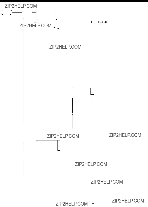
Calibration
Calibrate the heading sensor against magnetic field distortion aboard the boat as below. Do not turn off the power during the calibration.
1.Find a calm and clear area without current, wind, swell or waves.
2.Steer the boat clockwise or counterclockwise in a circular course. Take about two minutes to complete the circle (at about 3 kt). While turning the boat, go to step 3.
2 minutes for a circle (at about 3 kt)
Course to follow for calibration
Notes: Speed higher than 3 kt may result in calibration error.
3.Press the [MENU] key once or twice to open the menu.
4.Choose HDG SETUP and then press the [MENU] key. (It may take several seconds before the HDG SETUP menu appears.)
* = DAMPING shown on
HDG SETUP menu
5. Choose CALIBRATION and then press the [ENT] key.

1. OPERATION
CALIBRATION ?
ARE YOU SURE ?
YES NO
Calibration prompt
6.Choose YES and then press the [ENT] key. The display shows ???CALIBRATION????? during calibration. (To cancel calibration, press the [MENU] key. You cannot cancel calibration except when SAMPLING is showing ????????.)
7.Continue turning the boat in a circle until calibration results, NG (No Good) or OK, appear on the display. This takes about
CALIBRATION
SAMPLING : OK
CALIBRATION : OK
RESULT: OK
Calibration results
8.The display then shows ???PUSH ENT KEY.??? Push the [ENT] key to return to the HDG SETUP menu.
Note: If the results were unsuccessful, NG appears as the results. In this case, press the [MENU] key or the [ENT] key to return to the HDG SETUP menu. Redo the calibration referring to the installation manual for the heading sensor.
9.If you do not need to align heading or enter a damping factor

1. OPERATION
Offset
If there is a difference between sensor bearing and actual bearing, enter it as below. For example, if the sensor shows 70?? and the actual bearing is 75??, enter +5(??).
10.Choose OFFSET and press the [ENT] key.
11.Use ??? or ??? to choose minus or plus respectively, whichever is appropriate.
12.Press ??? to shift the cursor one place.
13.Use ??? or ??? to enter appropriate value.
14.Press ??? to shift the cursor one place.
15.Use ??? or ??? to enter appropriate value.
16.Press the [ENT] key.
17.Press the [MENU] key twice to finish, or go to step 15 to enter damping factor
Damping
Damping determines how sensitively the sensor responds to change of ship???s heading. Use a small value for faster response.???1??? is the default setting. Note that damping value must be received from the
18.Choose DAMPING and press the [ENT] key.
0
1
2
3
Damping options
19.Choose damping value. The larger the number the slower the response.
20.Press the [ENT] key.
21.Press the [MENU] key twice to close the menu.

2.MAINTENANCE,
TROUBLESHOOTING
 WARNING
Do not open the equipment.
Only qualified personnel should work inside the equipment.
2.1Maintenance
Check the following points regularly to maintain performance:
???Check that connections on the rear panel are firmly tightened and free of dust.
???Check that the ground system is free of rust and the ground wire is tightly fastened.
???Dust and dirt on the display unit can be removed with a soft cloth. Do not use chemical cleaners to clean the display unit ??? they can remove paint and markings.
2.2Error Messages
In addition to the alarm messages mentioned in Chapter 1, the

2. MAINTENANCE, TROUBLESHOOTING
2.3Diagnostic Test
The diagnostic test checks the ROM, RAM, AUX port, IN/OUT port, internal battery, keyboard and LCD for proper operation. Additionally it displays power source voltage, contrast and dimmer settings and program version number.
1.Press the [MENU] key once or twice to open the menu.
2.Select SYS SETUP and then press the [ENT] key.
3.Select TEST? and then press the [ENT] key. You are asked if you are ready to start the test.
TEST START ? (STOP: PWR OFF)
ARE YOU SURE ?
TEST START screen
4.Press ??? to select YES and then press the [ENT] key to start the test.
5.The equipment tests the ROM, RAM, AUX port, IN/OUT port and internal battery, displaying the results as OK or NG (No Good). For any NG contact your dealer for advice. ???-
Number of times test executed consecutively
TEST
XX.XX = Program version no.
TEST display
6.After the equipment has checked the items mentioned above, a beep sounds and the message PUSH KEY appears at the top
7.Press each key and cursor pad arrows one by one. The name of the key or cursor pad arrow pressed momentarily appears at the top
Note: If no control is operated within approx. five seconds, the equipment automatically proceeds to step 8.
2. MAINTENANCE, TROUBLESHOOTING
8.The equipment beeps and then displays the following message to inform you that it is now going to check the LCD:
<LCD CHECK>
ALL ON 2 SEC.
ALL OFF 3 SEC.
LCD CHECK screen
9.The LCD is checked and then the entire test is repeated. To stop the test, turn off the power.
2.4When BATTERY ALARM! Appears
A lithium battery (type:
1. Press the [MENU] key once or twice to open the menu. 2 Select SYS SETUP and then press the [ENT] key.
SYSTEM SETUP
TIME DISP : 24HOUR
BRG READ : MAGNETIC
MAG VAR. : AUTO E00
SIMULATOR: OFF
TEST?
EXCHANGE BATTERY?
SYSTEM SETUP menu
3.Select EXCHANGE BATTERY? and then press the [ENT] key. The display shows the following message:
EXCHANGE
BATTERY?
ARE YOU SURE?
YES NO
Exchange battery window
4.Press ??? to select YES and then press the [ENT] key. The following display appears. (At this time, the contents of the RAM are temporarily moved to the flash memory.)

2. MAINTENANCE, TROUBLESHOOTING
READY FOR
BATTERY CHANGE.
PRESS ANY KEY
TO SHUT DOWN.
Battery exchange confirmation window
5.Press any key to shut down the equipment.
6.Have a qualified technician replace the battery.
2.5Clearing Backup Data
You may clear all backup data (menu settings, trip, graph and odometer readings, etc.) to start afresh.
1.Press the [MENU] key once or twice to open the main menu.
2.Select RESET and then press the [ENT] key.
3.Select ALL BACKUP DATA? and then press the [ENT] key.
ERASE ALL BACKUP
DATA? (DEFAULT)
ARE YOU SURE?
YES NO
Prompt for erasure of backup data
4.Press ??? to select YES and then press the [ENT] key. The following display appears.
RESTART FOR
ERASING DATA.
HIT ANY KEY.
Prompt for restarting
5.Hit any key to erase all backup data. A beep sounds and then backup data is cleared.
MENU TREE
ALARM1
DIGITAL (Data Available: NONE, TEMP, POSN, HDG, ODO, CUR, HUM, SOG, DEPTH, TIME, WPT, ROT, XTE, POWER, PRE, STW, WIND, COG, TRIP, TD, TIMER,
ROT (30??, 60??, 90??/min)
RAI
HIGHWAY
BUZZ (SHORT, LONG, CONTIN.)
SPEED (OFF, 30.0 kt, LOW, HIGH, INSDE, OUTSD)
TEMP (OFF, +32.00??F, LOW, HIGH, INSDE, OUTSD, SHEAR) DEPTH (OFF, 0.0 ft, LOW, HIGH, INSDE, OUTSD)

(Continued from previous page)
OFFSETS
SYS SETUP
I/O SETUP
TIME DIFF
DEPTH
WND DIRECT
TIME DISP (12 HOUR, 24 HOUR)
BRG READ (MAGNETIC, TRUE) MAG VAR. (AUTO, MANUAL)
SIMULATOR (OFF, ON) TEST?
EXCHANGE BATTERY?
IN/OUT PORT (OFF, IN/OUT, AUX, BOTH) AUX PORT (OFF, IN/OUT, AUX, BOTH)
POWER OUT (OFF, ON)
IN/OUT PORT
AUX PORT
For selecting data sentence. See * below.
TD SETUP
LANGUAGE
UNITS
HDG SETUP (w/connection of
DISPLAY (XX.XXX', XX'XX.X", LORAN C TD, DECCA TD, LORAN A TD) LORAN C (Set Loran C chain and station pair. Default: 7980:
??? TD1, ??? TD2
DECCA (Set Decca chain and station pair. Default:
LORAN A (Set Loran A chain and station pair. Default:
ENGLISH, Others
TEMP (??C, ??F) (XX.XX, XX.X)
DIST/SPD (NM, KT; KM, KM/H; SM, MPH) DEPTH (M, FT, FA, PB)
WIND SPD (KT, KM/H, MPH, M/S) WIND (OFF, 1, 5, 10 min)
(TRUE, APP)
CALIBRATION (YES, NO) OFFSET
*= APB, BWC, BWR, CUR, DBK, DBS, DBT, DPT, GGA, GLC, GLL, GTD, HDT, HDG, HDM, MDA, MTW, MWV, RMB, RMC, ROT, VBW, VDR, VHW VTG, VWR, VWT, XTE, ZDA

LORAN C/ A CHAINS
Loran C
Loran A
Loran A station pair (Cannot enter same pair.)
1L0, 1L1, 1L4, 1L5, 1L6, 1L7, 1S1, 1S2, 1S3, 1S4, 1S6, 2H5, 2H6, 2S0, 2S1, 2S2, 2S3, 2S4, 2S5, 2S6, 2S7
DECCA CHAINS
FURUNO
SPECIFICATIONS OF
2.2Input/output Data
This page is intentionally left blank.

INDEX
*
A
B
C
D
G
H
I
M
O
P
R
S
T
U
W
X
Z