Nishinomiya, Japan
Telephone :
Telefax :
PUB.No.
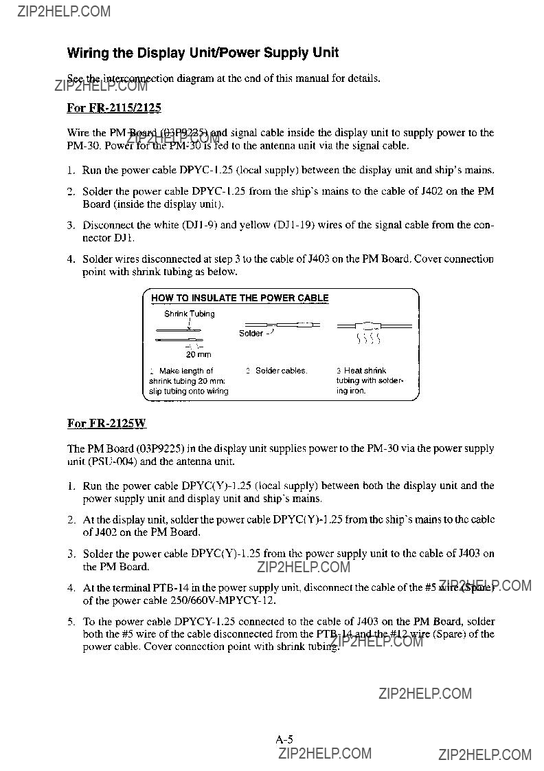
( DAMI )
Your Local Agent/Dealer
FIRST EDITION : JAN. 1988
L : JUL. 05,2002
*00080689900*
*00080689900*
* 0 0 0 8 0 6 8 9 9 0 0 *
*OME30200L00*
*OME30200L00*
* O M E 3 0 2 0 0 L 0 0 *


2.4 Adjustment at Installation
The
Adjustment Procedure
1.Confirm the front cover of the Performance Monitor is firmly secured with 8 fixing screws. (If not, microwave leakage will occur, resulting in misadjustment of attenuator ATT02 and eventual poor indicating accuracy.) Note that it is prohibited to open the front cover.
2.Remove the cap bolts of attenuators ATT01 (RX) and ATT02 (TX) provided on the top side of the Performance Monitor.
3.Put the radar in transmit mode.
4.Set the radar controls as follows:
5.Activate the Performance Monitor by operating the switch on the radar display, or by turning on the POWER switch of the Switch Box. Wait a while (about one minute) until the arc patterns displayed on the radar completely stabilized.
6.Operating the VRM control, measure the range to the innermost arc displayed on the radar screen.
7.Adjust attenuator ATT01 of the receiving circuit so that the innermost arc is displayed within the range 12 ??0.5 nm. Clockwise rotation of ATT01 increases the range; counterclockwise rotation decreases it.
Note: Arcs may disappear or freeze when the attenuator setting is out of the adjustment range, and adjustment of the attenuator alone cannot clear the problem. In this case, turn the attenuator fully counterclockwise, turn it about 1 1/2 turns and then turn the power off and on again. Adjust the attenuator slowly in about 5 degree turns; a slight turn yields large change.
8.Adjust transmitting circuit???s attenuator ATT02 so that the outermost arc (4th from inside) is slightly visible. Clockwise rotation of ATT02 increases the intensity of the arcs; counterclockwise rotation decreases it.
12