Nishinomiya
Pub. No.
( YOSH )
The paper used in this manual is elemental chlorine free.
FURUNO Authorized Distributor/Dealer
FIRST EDITION : JUN. 2004
A3 : OCT. 24, 2006
*00014970000*
*00014970000*
* 0 0 0 1 4 9 7 0 0 0 0 *
*OME20300A30*
*OME20300A30*
* O M E 2 0 3 0 0 A 3 0 *
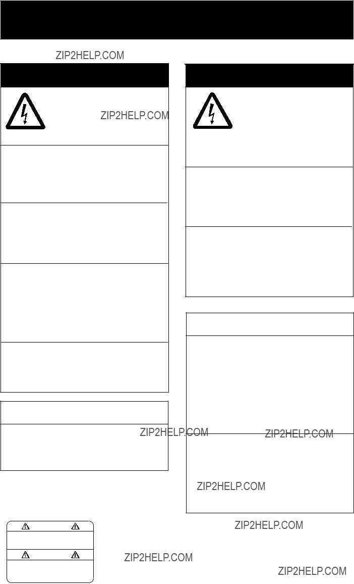

 SAFETY INSTRUCTIONS
 WARNING
Do not open the equipment.
Only qualified personnel should work inside
the equipment.
Do not disassemble or modify the equipment.
Fire, electrical shock or serious injury can result.
Use the proper fuse and power cable.
Fuse rating is shown on the equipment. Use of a wrong fuse can result in damage to the equipment.
Immediately turn off the power at the switchboard if the equipment is emitting smoke or fire.
Continued use of the equipment can cause fire or electrical shock. Contact a FURUNO agent for service.
Do not place any object near the exhaust or intake vent.
Fire may result.
 CAUTION
Do not connect/disconnect the signal cable while turning the power on.
The unit may be damaged.
A warning label is attached to the equipment. Do not remove the label. If the label is missing or damaged, contact a FURUNO agent or dealer.
 WARNING
Do not open the cover unless totally familiar with electrical circuits and service manual.
Improper handling can result in electrical shock.
Turn off the power at the switchboard before beginning the installation.
Fire or electrical shock can result if the power is left on.
Do not install the equipment where it may get wet from rain or water splash.
Water in the equipment can result in fire, electrical shock or damage to the equip- ment.
 CAUTION
Observe the following compass safe distances to prevent interference to a magnetic compass:
When lifting the display unit, hold it together with the hard cover.
Grasping by the hard cover alone may allow the display unit to fall, resulting in possible bodily injury or damage to the equipment.
i

TABLE OF CONTENTS
ii

FOREWORD
A Word to the Owner of the
FURUNO Electric Company thanks you for purchasing the
For over 50 years FURUNO Electric Company has enjoyed an enviable reputation for quality and reliability throughout the world. This dedication to excellence is furthered by our extensive global network of agents and dealers.
Your equipment is designed and constructed to meet the rigorous demands of the marine environment. However, no machine can perform its intended function unless properly installed and maintained. Please carefully read and follow the operation, installation and maintenance procedures set forth in this manual.
We would appreciate feedback from you, the
Thank you for considering and purchasing FURUNO.
Features
???Main or remote display for radars, video sounders, sonars, plotter. Compatible equipment:
???High resolution display of 1024 x 768dot (XGA)
???Brightness of 1,000 cd/m2 (maximum) and 5 cd/m2 (minimum) for comfortable viewing day and night
???Landscape orientation
???Wide viewing angle for observation by more than one person
???
iii
SYSTEM CONFIGURATION
RGB
 About the TFT LCD
The TFT LCD is constructed using the latest LCD techniques, and displays 99.99% of its pixels. The remaining 0.01% of the pixels may drop out or blink, how- ever this is not an indication of malfunc- tion.
iv

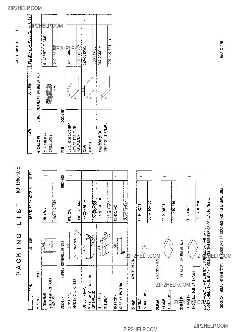
EQUIPMENT LISTS
Standard supply
Option
* = See packing list at the end of this manual.
v

1. MOUNTING
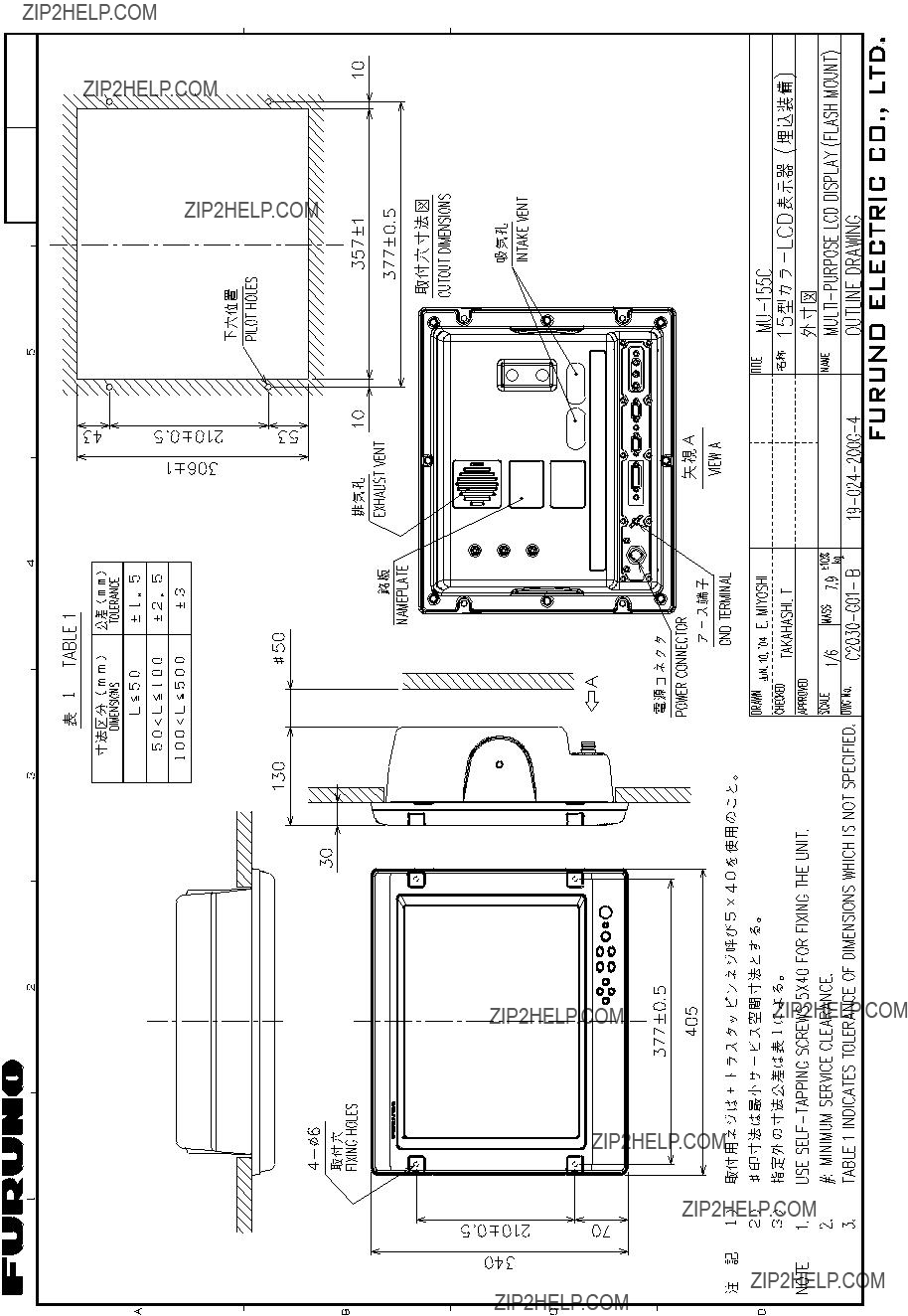
Refer to the outline drawing at the end of this manual for mounting dimensions.
Note: A grass plate covers the LCD. For this reason, handle the unit carefully.
1.1 Display Unit
The display unit may be mounted on a desktop (optional hanger required) or flush mounted in a panel.
When selecting a mounting location, keep in mind the following points:
???Locate the unit out of direct sunlight.
???Select a location where the display can be easily viewed and the controls can be easily operated.
???Leave sufficient space around the unit for servicing and maintenance. See the outline drawing for minimum servicing space.
???The unit weighs 7.9 kg (flush mounting)/9.1 kg (desktop mounting). Be sure the mounting location is strong enough to support the weight of the unit.
???Locate the unit away from areas subject to water splash and rain.
1
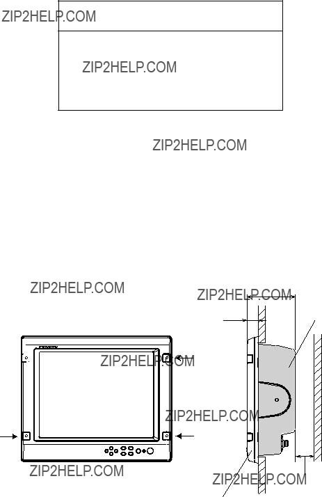
Flush mounting
See the outline drawing at the end of this manual for mounting dimensions.
 CAUTION
Hold the hard cover and display unit together when lifting the display unit.
The display unit may fall out if only the hard cover is held.
1.Remove the hard cover from the unit.
2.Using the paper template supplied in the installation materials, make a cutout in the mounting location.
3.Set the display unit to the cutout, and fasten it with four
Note: Hex head bolts may also be used to fasten the display unit. However, their lengths must be 10 mm longer than the wall thickness.
130
Cosmetic cap 


Minimum: 50
Waterproofing: IPX5
Mounting dimensions
4.Attach the cosmetic caps (supplied as accessories) to the display unit at the locations shown in the drawing above.
5.Attach hard cover to protect the LCD.
2

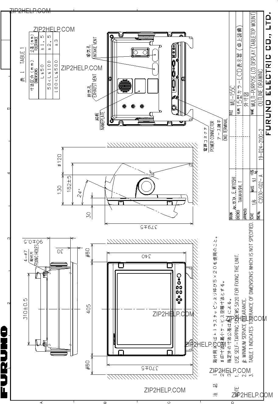
Desktop mounting
The display unit can be mounted on a desktop, using the optional hanger, Type:
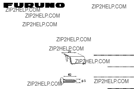
Contents of hanger mounting kit
1. Fasten the hanger to the mounting location with four
Note: Do not mount the unit where the exhaust or intake vent may be obstructed.
Display unit, rear view
2.Screw knob bolts in unit.
3.Set unit to hanger, and then tighten knob bolts.
4.Remove the hard cover from the unit.
5.Attach the cosmetic caps (supplied as accessories) to the unit at the locations shown in the drawing below.
6.Attach hard cover to protect the LCD.
Cosmetic cap 

Knob bolt
Hanger
Desktop mounting
3
1.2 Remote Controller
Write the device name (ex.
VIDEO1 VIDEO2 VIDEO3
RGB 1 :
RGB2 :
DVI :
VIDEO1:
VIDEO2:
VIDEO3:
Sticker
Remote controller
 WARNING
Ensure battery polarity is correct.
Wrong polarity may cause the batteries to explode.
4

2. WIRING
Connect external equipment to the
CCD camera, Video recorder, etc.
RGB2
RGB1
Display unit, rear view
5
Port, cable and connectable equipment
Grounding
Fasten the ground wire (local supply) between the ground terminal on the display unit and the ship???s superstructure. The length should be as short as possible.
Note: Use a 
 ) to make the ground connection at the display unit. Do not use an
  ).
).
6
3. ADJUSTMENTS
Adjust the
Note: The example screens shown in this manual may not match the screens you see on your display. The screen you see depends on your system configuration and equipment settings.
3.1 RGB/DVI Setting
RGB1 and RGB2 screens can be adjusted independently. Also, DVI screen can be adjusted similarly.
1.Press the [MENU] key to show the main menu.
The main menu is erased automatically with no operation for one minute.
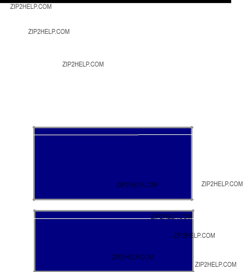
2.Press the [???] or [???] key to select RGB1, RGB2 or DVI as appropriate.
RGB1 RGB2 DVI VIDEO1 VIDEO2 VIDEO3 OSD SYSTEM
RGB1 (RGB2) setting menu
RGB1 RGB2 DVI VIDEO1 VIDEO2 VIDEO3 OSD SYSTEM
DVI setting menu
3.Press the [???] or [???] key to select the item to adjust.
4.Press the [???] or [???] key to adjust.
5.Press the [MENU] key to close the menu.
7
*: Warm color??? 5500K, 6500K, 7000K, 8000K ??? Cold color
**: Select NORMAL to use the SXGA signal from a radar or scanning sonar. Note that both left and right edges may be in black. For VGA and XGA signals, FULL and NORMAL are available.
***: Adjust H_SIZE and V_SIZE properly. Otherwise, unwanted image may appear outside of the display area.
Note: When the characters are not clear, adjust PHASE and SHARPNESS.
8
3.2 VIDEO Setting
VIDEO1, VIDEO2 and VIDEO3 screens; that is, the
1.Press the [MENU] key to show the main menu.
2.Press [???] or [???] to select VIDEO1, VIDEO2 or VIDEO3 as appropriate.
RGB1 RGB2 DVI VIDEO1 VIDEO2 VIDEO3 OSD SYSTEM
VIDEO1 (2 or 3) setting menu
3.Press the [???] or [???] key to select the item to adjust.
4.Press the [???] or [???] key to set.
5.Press the [MENU] key to close the menu.
9

3.3 Menu Window Setting
3.3.1 Adjusting the menu window
The menu window can be moved and translucentized on the OSD (On Screen Display) menu.
1.Press the [MENU] key to show the main menu.
2.Press the [???] or [???] key to select OSD.
RGB1 RGB2 DVI VIDEO1 VIDEO2 VIDEO3 OSD SYSTEM
CUSTOM NAME
RGB1 = RGB1______
RGB2 = RGB2______
DVI = DVI_______
VIDEO1 = VIDEO1____
VIDEO2 = VIDEO2____
VIDEO3 = VIDEO3____
OSD menu
3.Press [???] or [???] to select the menu item you want to adjust.
4.Press [???] or [???] to adjust.
5.Press the [MENU] key to close the menu.
10
3.3.2Changing the signal name
You can change the signal name which is shown on the DISP or PIP window, described in the next chapter. It is useful to use the name of the device connected (ex.
1.Press the [MENU] key to show the main menu.
2.Press the [???] or [???] key to select OSD.
CUSTOM NAME area
RGB1 RGB2 DVI VIDEO1 VIDEO2 VIDEO3 OSD SYSTEM
CUSTOM NAME
RGB1 = RGB1______
RGB2 = RGB2______
DVI = DVI_______
VIDEO1 = VIDEO1____
VIDEO2 = VIDEO2____
VIDEO3 = VIDEO3____
OSD menu
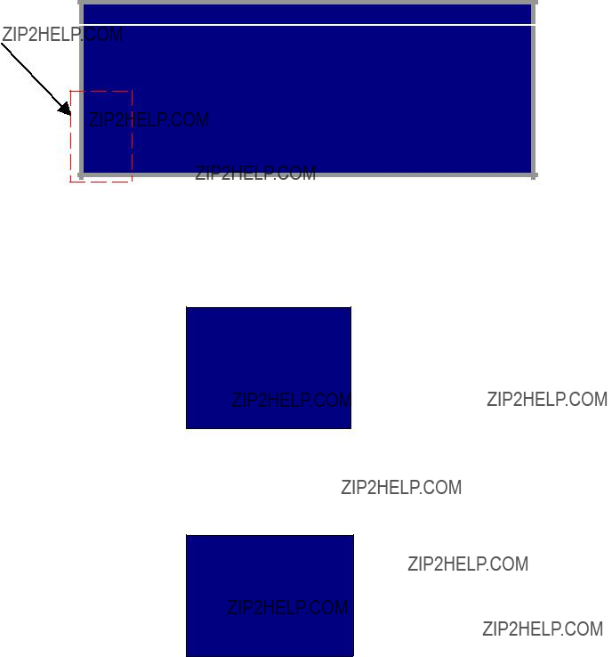
3.Press the [???] or [???] key to select the signal to change its name in CUSTOM NAME area. In the example above, RGB1 is chosen.
4.Press the [???] key to select the character you want to change. In the example below, ???G???
is selected.
CUSTOM NAME
RGB1 = RGB1______
RGB2 = RGB2______
DVI = DVI________
VIDEO1 = VIDEO1____
VIDEO2 = VIDEO2____
VIDEO3 = VIDEO3____
5.Press the [???] or [???] key to select appropriate alphanumeric character. In the example below, ???5??? is selected.
CUSTOM NAME
6.To change another signal name, press [???] and then press [???] or [???] to select it.
7.Press the [MENU] key to close the menu.
11
3.4 Remote Controller Setting
A remote controller can be set to be operative with a specific display unit, in the case of multiple
1.Press the [MENU] key to show the main menu.
2.Press the [???] key to select SYSTEM.
SYSTEM menu
3.Select INFRARED REMOTE.
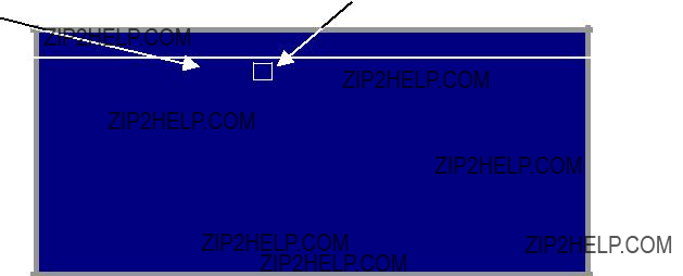
4.Point the remote controller toward the display unit, and press any key on the remote controller. The current setting of remote controller is shown inside the remote controller setting square.
5.Press the [RGB2] and [BRILL +] keys together on the remote controller to change the remote controller ID among A, B, C and D.
Your selection appears inside the square.
6.Press the [???] or [???] key so that the display unit ID is the same as the remote controller ID in the square.
7.Press the [MENU] key to close the menu.
12
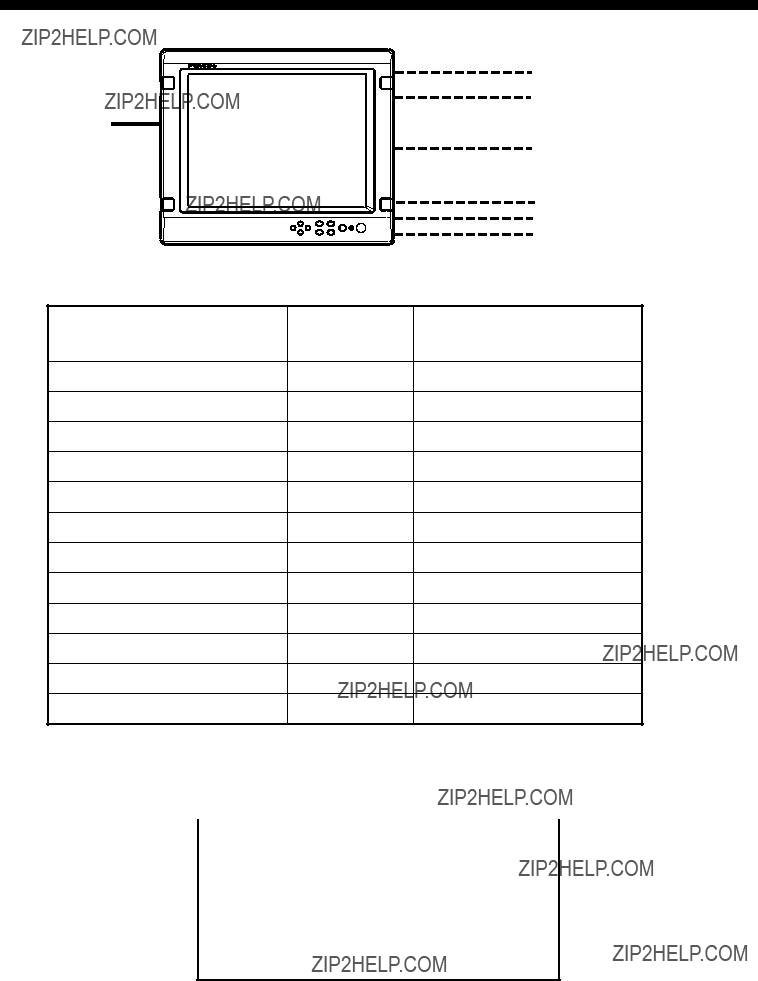
4. OPERATION
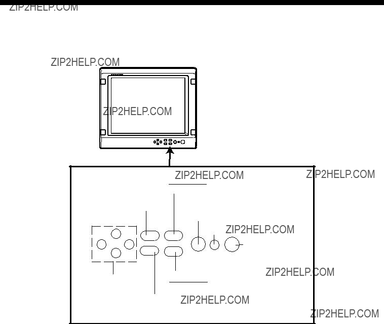
4.1 Controls
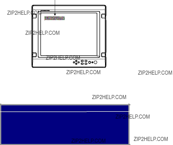
Display unit
DISP key
Shows the DISPLAY selection window.
MENU key
Shows the main menu.
Power key
LED
Optical sensor
Arrow keys Selects menu item.
PIP key
Shows the PIP selection window.
BRILL key
Shows the BRILL adjustment window.
Display unit
Power key: Press the power key ( ) to turn the power on or off.
LED: The LED changes color according to signal status as below.
Green: The selected signal to be displayed is input correctly from the external device.
Orange: The selected signal to be displayed is not input from the external device for five seconds.
13
Remote controller
VIDEO1 VIDEO2 VIDEO3
PIP1 PIP2 PIP3
BRILL + MENU
*: When a
**: When the previous selection is PIP1, 2 or 3, it is erased by pressing these keys.
***: When the previous selection is VIDEO1, 2 or 3, these keys are not available.
For PIP
14

4.2 Adjusting Display Brilliance
The display brilliance can be adjusted as follows.
1. Press the [BRILL] key on the display unit to show the BRILL adjustment window. BRILL 50
BRILL window
2.Press the [???] or [???] key to adjust the brilliance. (Setting range: 1 to 50) You can also adjust brilliance by pressing the [BRILL] key.
3.Press the [???] or [???] key to close the window.
The window is erased when there is no operation within five seconds.
Note: Avoid excessively low brilliance to prevent display irregularities.
15
4.3 Choosing Source for Main Picture
Choose the signal to display on the entire screen as follows:
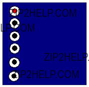
1.Press the [DISP] key to show the DISP selection window.
Signal names can be changed. For detail, see ???3.3.2 Changing the signal name???.
RGB1
RGB2
DVI
VIDEO1
VIDEO2
VIDEO3
DISP selection window
2.Press the [???] or [???] key to select a signal.
You can also select the signal by pressing the [DISP] key continuously.
DVI: The signal from the DVI port is displayed on the entire screen.
3.Press the [???] or [???] key to close the window.
The window is erased when there is no operation within five seconds.
Note: The name of the selected signal appears at the right top corner for five seconds after the DISP selection window is erased.
16

4.4 Choosing Source for
Choose the source for the
Note: The size of the
1.With the RGB1, RGB2 or DVI display shown, press the [PIP] key.
The PIP selection window appears. Signal names can be changed. For detail, see ???3.3.2 Changing the signal name???.
VIDEO1
VIDEO2
VIDEO3
OFF
PIP window
2.Press the [???] or [???] key to select the VIDEO port desired.
VIDEO can be also selected by pressing the [PIP] key continuously. To turn off the
3.Press the [???] or [???] key to close the window.
Note: The
17
5.MAINTENANCE,
TROUBLESHOOTING
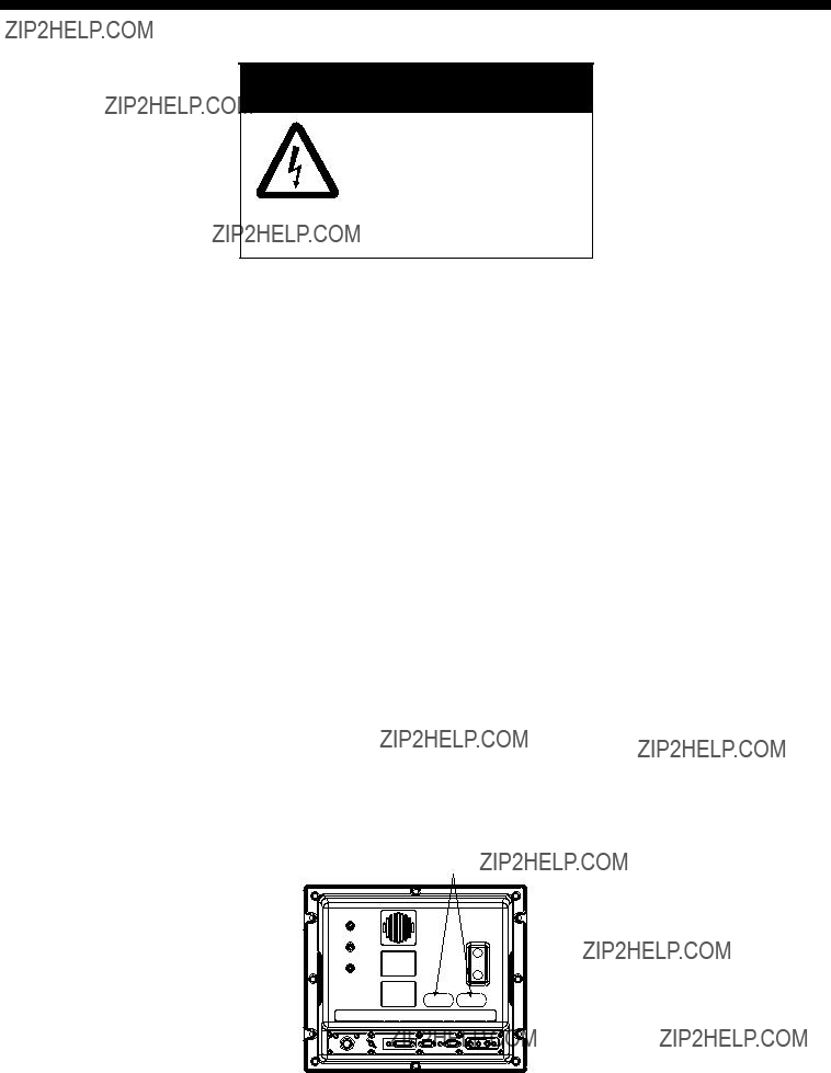
 WARNING
ELECTRICAL SHOCK HAZARD
Do not open the equipment.
Only qualified personnel should work inside the equipment.
5.1 Maintenance
Routine maintenance
Regular maintenance is important for good performance. Check the following on a regular basis to keep the equipment in good operating condition.
???Check that the connectors at the rear of the display unit are tightly fastened.
???Check the ground wire and ground terminal for rust. Clean if necessary. Confirm that the ground wire is tightly fastened.
???Remove dust and dirt from the display unit and LCD with a dry, soft cloth. Do not use chemical cleaners to clean any part of the display unit ??? they can remove paint and markings.
???Wipe the LCD carefully to prevent scratching, using tissue paper and an LCD cleaner. To remove dirt or salt deposits, use an LCD cleaner, wiping slowly with tissue paper so as to dissolve the dirt or salt. Change paper frequently so the salt or dirt will not scratch the LCD. Do not use solvents such as thinner, acetone or benzene for cleaning.
???Clean the filter at the intake vent regularly. To remove the filter, grasp the intake vent with fingers and pull forward. Use an air blower to remove dust and dirt from the filter. If it is particularly dirty, wash it in water or mild detergent and then let it dry. When reattaching the filter, be sure it is not caught in the holes for the intake vent.
Intake vent
Display unit, rear view
18
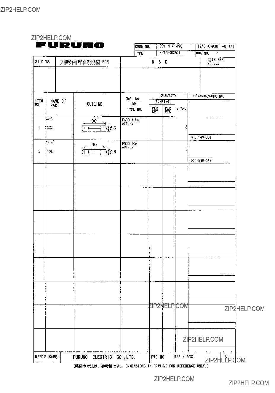
Fuse replacement
The fuse in the power cable protects the equipment from internal fault and overcurrent. If the fuse blows, find the cause before replacing it. If the fuse blows again after replacement, request service.
 WARNING
Use the proper fuse.
Use of a wrong fuse can cause fire or damage to the equipment.
Battery replacement
The remote controller has two AA batteries. If the distance from which the remote controller can be operated has decreased, change the battery.
Note: Replace all batteries together. Do not mix old and new batteries.
 WARNING
Ensure battery polarity is correct.
Wrong polarity may cause the batteries to explode.
5.2 Troubleshooting
The table below provides troubleshooting procedures to use when no picture appears. If you cannot restore the picture, do not attempt to check inside the equipment ??? there are no user serviceable parts inside. Refer any work to a qualified technician.
Troubleshooting table
You can confirm which signals are currently input in the SYSTEM menu.
VIDEO1: NTSC
VIDEO2: PAL
VIDEO3: NO SIGNAL
PROGRAM NO. *****
SYSTEM menu
19

5.3 Clearing the Memory
You may want to clear the memory to start afresh with default settings. You can do this as follows:
1.Press the [MENU] key to show the main menu.
2.Press the [???] keys to open the SYSTEM menu.
3.Select DEFAULT RESET by arrow keys.
4.Press the [???] key to select YES.
VIDEO3: NO SIGNAL
PROGRAM NO. *****
SYSTEM menu
5.Press the [???] key again to select ???reset???.
6.Press the [MENU] key to close the menu.
20
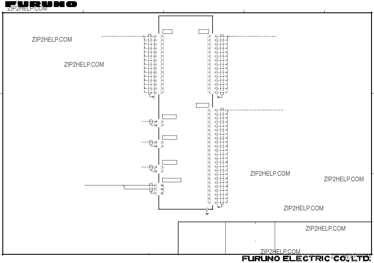
SPECIFICATIONS OF
1.5Input signal
3 ENVIRONMENTAL CONDITION
3.1Ambient temperature
This page is intentionally left blank.
??????/????????????????????????????????????????????????????????????????????????????????????????????????????????????????????????????????? ???????????????????????????????????????
TWO TYPES AND CODES MAY BE LISTED FOR AN ITEM. THE LOWER PRODUCT MAY BE SHIPPED IN PLACE OF THE UPPER PRODUCT.
QUALITY IS THE SAME.
A
?????? ??????????????????????????????
C???????????????????????????
????????????????????????????????????
?????????RCA????????????????????????2.5C2V???3C2V????????????????????? ???????????????????????????
*3
*4
*4
*4
???????????? RADAR
NOTE
*1. USER SUPPLY.
*2. OPTION.
*3. FITTED AT FACTORY.
*4. RECOMMENDED CONNECTOR AND CABLE:
RCA METAL CONNECTOR AND CABLE 2.5C2V, 3C2V OR EQUIVALENT. *5. SHIPYARD SUPPLY.