OWNER???S GUIDE
PLHV42P8KC
READ AND SAVE THESE INSTRUCTIONS
Range Hood
P/N 316 137 200
LI1NUA
OWNER???S GUIDE
PLHV42P8KC
READ AND SAVE THESE INSTRUCTIONS
Range Hood
P/N 316 137 200
LI1NUA

Product Registration
Register your Product
The
Thank you for choosing this appliance. The information contained within this Owner???s Guide will instruct you on how to properly operate and care for your range hood. Please read through the information contained in your literature pack to learn more about your new appliance.
Record Your Model and Serial Numbers
Record in the space provided below the model and serial numbers found on the serial plate located on the right hand side of the range hood.
Model Number: ___________________________________________________
Serial Number: ___________________________________________________
Date of Purchase: _________________________________________________
This Owner???s Guide contains general operatinginstructionsforyourrange hood and feature information for several models. Your range hood may not have all the described features.
Note: The instructions appearing in this Owner???s Guide are not meant to cover every possible condition and situation that may occur. Common sense and caution must be practiced when installing, operating and maintaining any appliance.
2

Important Safety Instructions
READ AND SAVE THESE INSTRUCTIONS
Take care when using cleaning agents or detergents.
Suitable for use in household cooking area
CAUTION - To reduce risk of fire and to properly exhaust air, be sure to duct air outside ??? Do not vent exhaust air into spaces within walls or ceilings or into attics, crawl spaces, or garages.
CAUTION - For General Ventilating Use Only. Do Not Use To Exhaust Hazardous Or Explosive Materials And Vapors.
WARNING ??? TO REDUCE THE RISK OF FIRE, ELECTRIC SHOCK, OR INJURY TO PERSONS, OBSERVE THE
FOLLOWING:
a.Use this unit only in the manner intended by the manufacturer. If you have questions, contact the manufacturer.
b.Before servicing or cleaning unit, switch power off at service panel and lock the service disconnecting means to prevent power from being switched on accidentally. When the service disconnecting means cannot be locked, securely fasten a prominent warning device, such as a tag, to the service panel.
WARNING ??? TO REDUCE THE RISK OF A RANGE TOP GREASE FIRE:
a.Never leave surface units unattended at high settings. Boilovers cause smoking and greasy spillovers that may ignite. Heat oils slowly on low or medium settings.
b.Always turn hood ON when cooking at high heat or when cooking flaming foods.
c.Clean ventilating fans frequently. Grease should not be allowed to accumulate on fan or filter.
d.Use proper pan size. Always use cookware appropriate for the size of the surface element.
WARNING ??? TO REDUCE THE RISK OF INJURY TO PERSONS IN THE EVENT OF A RANGE TOP GREASE FIRE,
OBSERVE THE FOLLOWING:
a.SMOTHER FLAMES with a
b.NEVER PICK UP A FLAMING PAN ??? You may be burned.
c.DO NOT USE WATER, including wet dishcloths or towels ??? a violent steam explosion will result.
d.Use an extinguisher ONLY if:
1.You know you have a Class ABC extinguisher, and you already know how to operate it.
2.The fire is small and contained in the area where it started.
3.The fire department is being called.
4.You can fight the fire with your back to an exit.
WARNING ??? TO REDUCE THE RISK OF FIRE, ELECTRIC SHOCK, OR INJURY TO PERSONS, OBSERVE THE
FOLLOWING:
a)Installation work and electrical wiring must be done by qualified person(s) in accordance with all applicable codes and standards, including
b)Sufficient air is needed for proper combustion and exhausting of gases through the flue (chimney) of fuel burning equipment to prevent back drafting. Follow the heating equipment manufacturer???s guideline and safety standards such as those published by the National Fire Protection Association (NFPA), and the American Society for Heating, Refrigeration and Air Conditioning Engineers (ASHRAE), and the local code authorities.
c)When cutting or drilling into wall or ceiling, do not damage electrical wiring and other hidden utilities.
d)Ducted fans must always be vented to the outdoors.
WARNING - TO REDUCE THE RISK OF FIRE, USE ONLY METAL DUCTWORK.
 WARNING
Electrical Shock Hazard - Can result in serious injury or death. Disconnect appliance from electric power before servicing.
If equipped, the fluorescent light bulb contains small amounts of mercury which must be recycled or disposed of according to Local, State, and Federal Codes.
3
Installation
FOR RESIDENTIAL USE ONLY
NOT TO BE INSTALLED OVER GAS GRILLS
PLEASE READ ENTIRE INSTRUCTIONS BEFORE PROCEEDING.
INSTALLATION MUST COMPLY WITH ALL LOCAL CODES.
IMPORTANT: Save these Instructions for the Local Electrical Inspector???s use. INSTALLER: Please leave these Instructions with this unit for the owner.
OWNER: Please retain these instructions for future reference. Safety Warning: Turn off power circuit at the service entrance and lock out
panel, before wiring this appliance. Requirement: 120 V AC, 60 Hz. 15 or 20 A
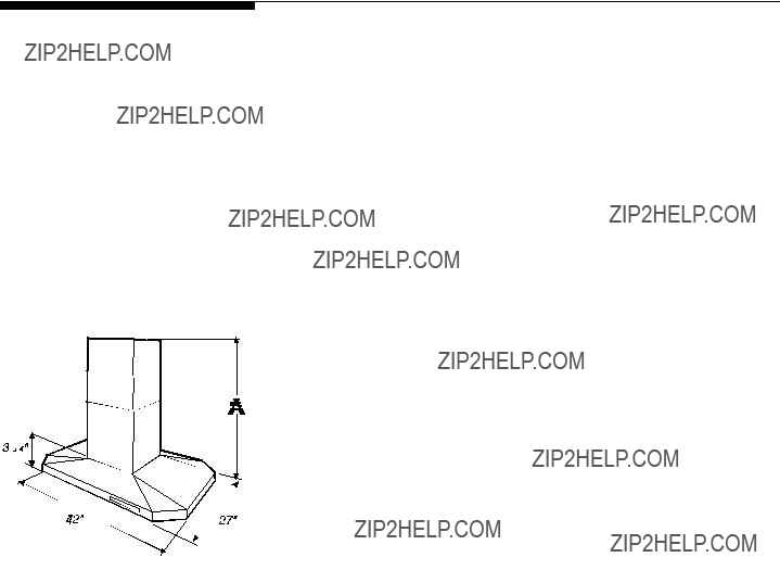
Dimensions - Table 1
max. 48 5/16
Weight: 86 pounds
Diameter of Transition 8???
Diameter of exhaust Duct required 8???
Note: All dimensions are shown in inches.
Figure 1** Dimensions are given from base of hood to ceiling, and include clearance required for installation.
Considerations before installing Hood
1.For the most efficient air flow exhaust, use a straight run or as few elbows as possible.
CAUTION: Vent unit to outside of building, only.
2.If allowed in your area, use metallic flex ducting only to connect rigid duct directly to transitions.
3.COLD WEATHER installations should have an additional backdraft damper installed to minimize backward cold air flow and a nonmetallic thermal break to minimize conduction of outside temperatures as part of the ductwork. The damper should be on the cold air side of the thermal break. The break should be as close as possible to where the ducting enters the heated portion of the house.
4.Hood installation height above cooktop is the users preference P (see Figure 2). The lower the hood above the cooktop, the more efficient the capturing of cooking odors, grease and smoke. Be sure that your hood model fits your installation.
4

Installation
Tools required for installation
Screw driver (pozidrive n??2 , torx 10 and 20) Allen spanner 4mm
Shifting spanner 10mm pipe wrench 3/8
Electric drill with twist bit ?? 10 mm
1.a) Select a hood preference height P (see Figure 2) that is comfortable for the user. (30??? - 36??? recommended, 24??? - 36??? allowed).
b)Calculate Hood height your installation H (see Figure 2). H =
c)Confirm that H is within the range of min to max H found for your hood. If not adjust your installation.
d)Calculate Chimney structure height S (use formulas in Figure 2, and check dimensions of your hood). Save this calculation for use later in the installation.
Preparation of Mounting Surface - Installing supports above ceiling drywall.
Note: Take into consideration the hood depth; your hood could be much deeper than the cooktop.
2.Mark center lines of cooktop or range on ceiling above. Use centerlines marked on ceiling to position the mounting template. Note location of hood front, side, and mounting holes indicated on template.
3.Remove and save template. Cut and remove ceiling drywall. Install suitable length 2" x 4" lumber between joists to provide chimney mounting points as shown in Fig. C and D. Use template for dimensions and required clearance.
Make sure to affix the added lumber firmly and level. Consult a profes- sional if you have difficulties or your installation is unique. Consult template and Figures 3. 4. 5.
Note the weight of the appliance. (see Table1).
4.Install exhaust duct (see Table 1 for size). Female end shall be
5.Install 1/2" electrical conduit in location marked on template and extend length S from ceiling.
6.Install drywall around duct and conduit; then refinish ceiling.
5
Installation
Figure 6
Appliance Installation
(Note: two people may be required for proper installation of model FIJI).
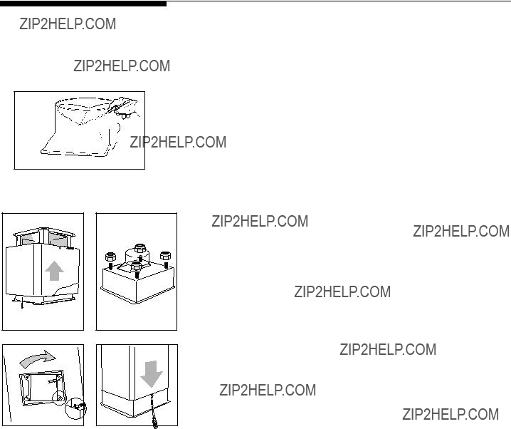
8.Install transition to top of hood (if removed for shipping). Snap damper into transition, foam tape up , with firm pressure at either end. Mark onto exterior of transition the 'V' location of the damper within. See Figure 6.
Note: Duct screws can ONLY go below this line.
9.Adjust chimney mounting structure to S dimension as determined in Step 1, page 5. Use 2 screws per attachment leg. Do not fasten to ceiling now.
10.Set chimney mounting structure on top of hood canopy. Attach nuts loosely. See Figure 8 and 9.
11.Fit duct piece on transition so that top end is
12.Remove chimney structure from hood canopy.
13.Install Ducting. Fasten duct to transition with screws and tape per code. Loosely fasten starter collar (included) flush to top of duct. Note: screws must not hamper the damper (see 8. above for screw location).
Loosely fasten starter collar (included) flush to bottom of duct.
14.To install Chimney Structure to ceiling, use a 10mm or adjustable wrench or flat head screwdriver. Drill pilot holes into ceiling. Attach mounting structure to joists with the 4 lag screws provided. (Keep 1/2" conduit inside structure.) See Figure 3.
15.Remove Chimney Cover's plastic protective film. Reassemble and fasten all 3 covers together with one vertical screw. See Figure 7. Slide over chimney structure and secure with 2 screws near ceiling.
16.To fasten the canopy use a 10mm or adjustable wrench. Affix nuts to top of canopy.
Do not tighten. Raise canopy up to chimney structure and twist in place. See Figure 9. Tighten nuts securely.
17.Ducting for all units: There should be no more than 1" gap between canopy ducting and house ducting. Adjust starting collar over both ducts. Tighten collar. Fasten duct with screws and tape per code. Make final angular adjustment to unit at ceiling if necessary, then securely tighten 4 ceiling lag screws if not already tightened.
6

Installation
Wiring to Power Supply
WARNING!
ELECTRICAL GROUNDING INSTRUCTIONS
THIS APPLIANCE IS FITTED WITH AN ELECTRICAL JUNCTION BOX WITH
3 WIRES, ONE OF WHICH (GREEN/YELLOW) SERVES TO GROUND THE
APPLIANCE. TO PROTECT YOU AGAINST ELECTRIC SHOCK, THE GREEN
AND YELLOW WIRE MUST BE CONNECTED TO THE GROUNDING WIRE
IN YOUR
HOME ELECTRICAL SYSTEM, AND IT MUST UNDER NO CIRCUMSTANCES
BE CUT OR REMOVED.
Warning: Turn off power circuit at the service panel before wiring this unit. 120 VAC, 15 or 20 Amp circuit required.
18.Remove
19.Remove the knockout and install the strain relief (conduit) connector (1/ 2") in junction box.
20.Run 3 wires; black, white and green (#16 AWG) in 1/2" conduit from service panel to junction box.
21.Connect black wire from service panel to black or red in junction box, white to white and green to
22.Close junction box cover, check all light bulbs to make sure they are secure in their sockets, then turn power on in service panel and check lights and blower operation per Care & Use section of this manual and install filters.
FINAL ASSEMBLY
23.For final Chimney Cover installation, DO NOT USE ELECTRIC SCREW
DRIVER.
Raise chimney covers and fasten in place with 2 screws if not already fastened. Figure 7. Remove one vertical screw holding covers together. See Figure 10.
Gently slide the outer and middle covers down and set on canopy. Raise the middle cover, align holes with lower cover and insert pin or wire to temporarily hold up. Fasten covers together using 2 screws through holes to permanently hold up.
NOTE: Do not overtighten and deform metal.
24. Make sure to leave this manual for the home owner.
7

Use and Care
Control Pad Functions
READ THE INSTRUCTIONS CAREFULLY BEFORE USING THE HOOD.
For satisfactory use of your hood, become familiar with the various functions of the hood as described below
Suction power 2 LED, this led is ON when suction power 2 is selected.
Motor OFF button
Suction power 3 LED, this led is ON when suction power 3 is selected.
Light OFF button
Light ON button
Figure 12
I n t e n s i v e Suction power LED, this led is ON when the i n t e n s i v e suction power is selected.
I n t e n s i v e Suction power button - this suction power will function for 10 mins. then the hood set again the p r e s e l e c t e d speed
Grease Filter Saturation LED
The Suction power 2 LED in Figure 12 is marked with an F. This LED will flash to remind you when the grease filter needs to be cleaned after 40 hours use. Follow the instructions for cleaning filters in this booklet. Once the grease filters have been cleaned, reset the reminder by pressing Motor OFF button for about 3 seconds until you hear the signal (beep).
Operating Instructions
The blower should be turned on for about 5 minutes before cooking in order to establish air currents upward through the hood.
Use the low speeds for normal use and the higher speeds for strong odors or fumes. Minimize cross drafts which will reduce the effectiveness of the hood.
8

Hood Cleaning
Be sure lights are cool before cleaning the hood.
To Clean Filters
???The metal grease filters will last forever. They are made of anodized aluminum
???It is recommended that the filters be washed at least once a month; they can be washed by hand or in the dishwasher.
???Drain water through edge holes and let each filter dry thoroughly before replacing it.
To Remove The Metal Grease Filters
???Turn blower and lights off.
???Push each handle towards the center and pull downwards Figure 13.
To Replace The Metal Grease Filters
??? Reverse procedure.
To Clean Hood Surface
???For general care, wipe the outside of the stainless steel, white, black or glass hood with sudsy water or household cleaners such as Fantastic?? or Formula 409??, rinse well and dry with clean soft cloth to avoid water marks.
???Wipe and dry brushed stainless steel in the same direction as the grain.
???Do not use abrasive products.
???To remove finger prints and give added shine use spray cleaners such as Stainless Steel Magic?? and Shimmer??.
9

Lights replacement
NOTE: Turn blower and lights off. Make sure the lights are cool. If new lights do not operate be sure lights are inserted correctly before calling service.
Replace Lights (Figure 14)
???Remove lens cover by removing screw and pulling cover down.
???Pull out fluorescent tube and replace with Philips Type
???Replace cover and secure with screw.
NOTE: Disconnect the hood from the electricity before checking or replacing fuses.
???Fuses are located on the bottom of blower behind filters.
???Remove cover and check fuses. Figure 15.
???Replace with type 5 x 20mm, 3.15A slow blow only. (Examples are Radio Shack Cat #
10
11

RANGE HOOD WARRANTY
Your range hood is protected by this warranty
In the U.S.A., your appliance is warranted by Electrolux Home Products North America, a division of White Consolidated Industries, Inc. We authorize no person to change or add to any of our obligations under this warranty. Our obligations for service and parts under this warranty must be performed by us or an authorized Electrolux Home Products North America servicer. In Canada, your appliance is warranted by WCI Canada,
Inc.
*NORMAL
RESPONSIBILITIES
OF THE CONSUMER
EXCLUSIONS
IF YOU NEED
SERVICE
This warranty applies only to products in ordinary household use, and the consumer is responsible for the items listed below:
1.Proper use of the appliance in accordance with instructions provided with the product.
2.Proper installation by an authorized servicer in accordance with instructions provided with the appliance and in accordance with all local plumbing, electrical and/or gas codes.
3.Proper connection to a grounded power supply of sufficient voltage, replacement of blown fuses, repair of loose connections or defects in house wiring.
4.Expenses for making the appliance accessible for servicing, such as removal of trim, cupboards, shelves,etc., which are not a part of the appliance when it was shipped from the factory.
5.Damages to finish after installation.
6.Replacement of light bulbs and/or fluorescent tubes (on models with these features).
This warranty does not cover the following:
1.CONSEQUENTIAL OR INCIDENTAL DAMAGES SUCH AS PROPERTY DAMAGE AND INCIDENTAL EXPENSES
RESULTING FROM ANY BREACH OF THIS WRITTEN OR ANY IMPLIED WARRANTY.
NOTE: Some states do not allow the exclusion or limitation of incidental or consequential damages, so this limitation or exclusion may not apply to you.
2.Service calls which do not involve malfunction or defects in workmanship or material, or for appliances not in ordinary household use. The consumer shall pay for such service calls.
3.Damages caused by services performed by servicers other than Electrolux Home Products North America or its authorized servicers; use of parts other than genuine Electrolux Home Products parts; obtained from persons other than such servicers; or external causes such as abuse, misuse, inadequate power supply or acts of God.
4.Products with original serial numbers that have been removed or altered and cannot be readily determined.
Keep your bill of sale, delivery slip, or some other appropriate payment record. The date on the bill establishes the warranty period should service be required. If service is performed, it is in your best interest to obtain and keep all receipts. This written warranty gives you specific legal rights. You may also have other rights that vary from state to state. Service under this warranty must be obtained by contacting Electrolux Home Products:
This warranty only applies in the 50 states of the U.S.A., Puerto Rico, and Canada. Product features or specifications as described or illustrated are subject to change without notice. All warranties are made by Electrolux Home Products North America, a division of White Consolidated Industries, Inc. In Canada, your appliance is warranted by WCI Canada, Inc.
12

demanded???assistanceengarantie,s???adresser??ElectroluxHomeProducts: ult??rieurspourrontvous??treconf??r??ssurlabasedelal??gislationenvigueurdanslesdiff??rents.Payspourla devaitser??v??ler.n??cessaireLapr??sentegarantie??critevousconf??redesdroitsl??gaux.sp??cifiquesDesdroits
.imm??diatement .4Produitsdontlesnum??rosdes??rieoriginauxont??t??retir??soualt??r??setnepouvantpas??treidentifi??s emploiimpropre,installationd???alimentationnonappropri??eoucausesdeforce.majeure obtenuesdansdescentresnonappartenant??ElectroluxHomeProducts;causesexternestellesque:abus,
.6Remplacementdeslampeset/outubesfluorescents(surlesmod??les??quip??sdeces.??l??ments) .5Dommagesauxfinitions??lasuitede.l???installation momentdelalivraisondelapartdel???usinede.production comprisleretraitdefournitures,meubles,armoiressuspendues,.etcquinefontpaspartiedel???appareilau .4Fraissoutenusafindegarantirl???acc??s??l???appareilpourlesinterventionsd???entretienouder??paration,y ??lectrique.domestique fusiblesgrill??s,r??parationdesconnexionsinterrompuesourectificationdespannesdel???installation .3Connexion??unesourced???alimentationavecmise??laterreayantunetensionappropri??e,remplacementdes hydrauliqueset/oudu.gaz
ASSISTANCE SIL???ONDEMANDE
EXCLUSIONS
DEL???ACHETEUR *RESPONSABILIT??
GARANTIEDELAHOTTEDECUISINE

11
deslampes Remplacement

10
Nettoyagedesfiltres
la.hotte S???assurerqueleslampessesoientrefroidiesavantd???effectuerlenettoyagede
NettoyagedelaHotte

9
R??duireaumaximumlescourantsdetiragetransversauxsusceptiblesder??duirel???efficacit??dela.hotte .intenses D??finirunevitesser??duitepourlesconditionsd???emploinormalesetunevitesseplus??lev??eencasdefum??eouodeurs tiragedescourantsd???air??traversla.hotte Nousconseillonsd???allumerlerotordeventilationenviron5minutesavantdecommencerlacuisson,afind???activerle Instructionsrelativesaufonctionnement
3secondesenviron,jusqu?????cequelesignal(bip)soit.activ?? l?????tatinitialdudispositifdesignalisationenmaintenantappuy??lepoussoird???extinctionmoteur(OFF)pendant
??teinte(OFF) Poussoirlampe
.s??lectionn??e d???aspiration3est lorsquelapuissance s???allume(ON) d???aspiration.3Ladel DELdepuissance
2,3,1,.... d???aspiration1, puissance poussoirde (ON)et moteurallum?? Poussoir
.s??lectionn??e d???aspiration2est lapuissance s???allume(ON)lorsque d???aspiration.2Ladel DELdepuissance
Figure12
.s??lectionn??e d???aspiration1est puissance lorsquela dels???allume(ON) d???aspiration.1La DELdepuissance
??teint(OFF) Poussoirmoteur
familiariseravectoutessesfonctions: Afindepouvoirutiliserlahottedefa??onsatisfaisanteilfautse LIREATTENTIVEMENTLESINSTRUCTIONSAVANTD???UTILISERLA.HOTTE
descommandes Fonctionsdupanneau
EmploierEntretien

8
.24Laisserlepr??sentmanuel??ladispositiondu.propri??taire
d??formerle.m??tal REMARQUE:Nepasserrerexcessivement,afind?????vitertoutrisquede
2vis,entantquefixation.provisoire entantquefixation.provisoireUnirlesdeuxcouverturesaumoyende aveclacouvertureinf??rieurepuisins??rerungoujonouunfilm??tallique puisins??rerla.hotteSouleverlacouverturecentrale,alignerlestrous Fairedescendrelentementlacouvertureexterneetlacouverturecentrale lescouverturesrestentunies(Figure.10) effectu??e(Figure.7)Retirerl???unedesvisverticalesquifontensorteque positionaumoyende2vis;sicetteop??rationn???apasencore??t??
MONTAGEFINAL
Entretiendupr??sentmanuel,puiseffectuerl???installationdes.filtres ventilation,surlabasedesindicationsfourniesdanslasectionEmploiet de.commandesContr??lerleslampesetlefonctionnementdurotorde douillescorrespondantespuisbrancherl???alimentationdepuislepanneau toutesleslampesafindev??rifierqu???ellessoientcorrectementfix??esaux .22Fermerlecouvercledelabo??tedesconnexions??lectriques,contr??ler
aufilvert/jaune(Figure.11) labo??tedesconnexions??lectriques,lefilblancaufilblancetlefilvert .21Connecterlefilnoirdupanneaudecommandesaufilnoirourougede
connexions.??lectriques ??lectriquesde1/2"entrelepanneaudecommandesetlabo??tedes .20Ins??rerlestroisfilsnoir,blancetvert(#16AWG)dansletubepourc??bles
illustr??danslaFigure.11 .18Retirerlecouvercledelabo??tedesconnexions??lectriques,comme
V,.A.C15ou20.Amp circuitd???alimentationdupanneaude.commandeAlimentationrequise:120 Avertissement:Avantdepr??parerlesconnexions??lectriques,interromprele
Branchementaur??seaud???alimentation??lectrique Installation

7
plafond,sicetteop??rationn???apasencore??t??.effectu??e del???unit??auplafond,puisserreravecforceles4visd???ancragefix??esau le.r??glementSin??cessaire,r??glerd??finitivementlapositionangulaire laconduiteaumoyendesvispuisappliquerlerubancommepr??vupar surlesdeuxconduitespuisserrercedernierdefa??on.appropri??eFixer l???installation.domestiqueAdapterlecollierdefixationpourlemontage espacelibresup??rieur??1"entrelaconduitedelahotteetcellede .17Conduitespourtouteslesunit??s:ilestpr??f??rabledenepaslaisserun
les??crous??.fond
les??croussurlapartielaplushautedela.hotte .16Pourfixerlahotte,utiliserunecl??10.mmouunecl??.r??glableAppliquer
.vis Enfilerlastructuredesupportpuisfixerpr??sduplafondaumoyende2 nouveaupuisfixerles3couverclesavecuneseulevisverticale(Figure.7) .15Retirerlefilmenplastiquedeprotectiondela.chemin??eAssembler??
.3) letubepourc??bles??lectriquesde1/2"??l???int??rieurdelastructure(Figure soliveauxenutilisantles4visd???ancragefourniesavec.l???appareilMaintenir trousdeguidageau.plafondAccrocherlastructuredesupportaux ouunecl??r??glable,oubienuntournevis??t??te.platePercerplusieurs Pourinstallerlastructuredesupportauplafond,utiliserunecl??10.mm
parfaitementalign??aveclefonddela.conduite Fixersansserrerlecollierdeconnexion(compris),enlemaintenant
Retirerlastructuredesupportdela.hotte
??croussansserrer(Figures8et.9) Positionnerlastructuredesupportausommetdela.hotteFixerles
Nepaseffectuerlafixationauplafondlorsdecette.phase d??critauPoint1??page.5Utiliser2vispourchaquesupportde.fixation AdapterlastructuredesupportenfonctiondelacoteS??tabliecomme
.8
personnespourraitser??v??ler.n??cessaire) (Remarque:pourinstallercorrectementlemod??leFIJI,lapr??sencededeux
Installationdel???appareil
Installation

??lectriques,puiseffectuerlefinissagedu.plafond .6Monterleplacopl??treautourdelaconduiteetdutubepourlesc??bles
du.plafond pointmarqu??surlegabaritdeper??ageetprolongerlalongueurSquipart .5Installeruntubepourc??bles??lectriquesde1/2"encorrespondancedu
conduitepluspetiteparrapportau.raccord plafondfinietdoit??tresolidementfix??aux.soliveauxNepasutiliserune
Marquerlepoidsdel???appareil(Tableau.1) gabaritdeper??ageetlesd??tailsreport??sdanslesFigures3,4et.5 interpelleruntechnicien.sp??cialis??Utiliserentantquer??f??rencele parfaitement??.platEncasdedifficult??soud???exigencesparticuli??res, libre.requisS???assurerquel?????l??mentenboissoitmont??solidementet et.DUtiliserlegabaritdeper??agepourd??finirlesdimensionsetl???espace (2"x4")pourl???ancragedelachemin??e,commeillustr??danslesFiguresC Ins??rerentrelesjointsun??l??mentenboisayantunelongueurappropri??e .3Retireretconserverlegabaritde.per??agePerceretretirerle.placopl??tre
.per??age c??t??delahotte,ainsiquedestrousdemontagereport??ssurlegabaritde legabaritde.per??agePrendrenotedespositionsdelapartieavantetdu .2Marquerauplafondl???axedelacuisineouduplandecuisson,enutilisant
nettementsup??rieure??celleduplande.cuisson Remarque:??valuerlaprofondeurdelahotte,quipourraitser??v??ler
plafondenplacopl??tre.
Conserverlescalculspouruneinstallation.ult??rieure report??esdanslaFigure2etenv??rifiantlesdimensionsdela.hotte) d)CalculerlahauteurdelastructuredesupportS(enutilisantlesformules l???installationenfonctiondesconditions.requises ./max.minreport??essurla.hotteDanslecascontraire,adapter c)Veiller??cequelahauteurHsoitcomprisedansl???intervalledesvaleurs
Op??rationspr??liminaires??l???installation(Figure2)
Installation

5
appropri??pour.l???installation fum??esera.efficaceVeiller??cequelemod??ledelahottechoisiesoit l???aspirationdesvapeursetdesodeursdecuisson,delagraisseetdela ??lafigure.2)Pluslahotteseraplac??eenbas,parrapport??lacuisine,plus ??tablieenfonctiondesexigencesdel???utilisateur(voiraussidimensionsP .4Lahauteurpourl???installationdelahottesurleplandelacuisinedoit??tre .l?????difice possibledupointd???entr??edescanalisationsdanslapartier??chauff??ede froiddelaprotectionthermiqueetdeplacerlaprotectionlepluspr??s des.canalisationsIlestopportund???installerleclapetsurlec??t??del???air pourminimiserl???influencedelatemp??ratureexterne??traversler??seau del???airfroidderetour,outre??uneprotectionthermiquenonm??tallique unclapetderetenuedesfum??espourr??duireaumaximuml?????coulement .3Les??quipementsinstall??sdansdesr??gionsauCLIMATFROIDdoiventavoir de.raccordement uniquementpourconnecterlaconduiterigidedirectementauxdispositifs .2Utiliserdescanalisationsflexiblesenm??tal,siautoris??esdansvotrer??gion, .l?????difice ATTENTION:??vacuerl???airdel???unit??exclusivement??l???ext??rieurde conduitelin??aireour??duireaumaximumlenombredescoudes.pr??sents .1Afind???obteniruneefficacit??maximumd?????vacuationdel???air,utiliserune Avantd???effectuerl???installationdelahotte
Diam??trerequispourlaconduited?????vacuation:8??? Diam??trederaccordement:8??? Poids:86pounds
Dimensions
4
conform??mentauxr??glementsmunicipauxainsiqu???auxloisprovincialeset.f??d??rales
 Avertissement
Informationsimportantesrelatives??las??curit??(suite)

3
Aptitude??l???emploidansl???environnementdomestique/cuisine desubstancesnettoyantesou.d??tergentes Faireextr??mementattentionlorsdel???emploi
LIREETVERCONSERLESPR??SENTESINSTRUCTIONS
??las??curit?? Informationsimportantesrelatives

2
Dated???achat:_____________________________________________________ Num??rodes??rie:_________________________________________________ Num??rodemod??le:_______________________________________________
.rangement plaquesignal??tiquesitu??esurlec??t??droitducadreavant,dansletiroirde
cette.hotte lesdocumentsquiaccompagnentl???appareilpourensavoirdavantagesur guidedel???utilisateurexpliquentcommentutiliseretentretenirla.hotteLire Mercid???avoirchoisicet.appareilLesrenseignementscontenusdansce
retourn??e??Frigidaire.Canada remplieenentier,sign??eet pr??alablementadress??edoit??tre LaCARTED???ENREGISTREMENT Enregistrerl???appareil
l???appareil Enregistrementde

Pi??cen??316137200
Hottedecuisine
LISEZETCONSERVEZCESINSTRUCTIONS
PLHV42P8KC
GUIDEDEL???UTILISATEUR