Notas importantes para el instalador
1.Lea todas las instrucciones contenidas en este manual antes de instalar el combinaci??n microondas / horno de pared.
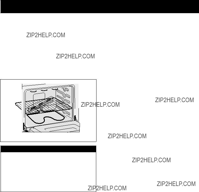
2.Saque todo el material usado en el embalaje del compartimiento del horno antes de conectar el suministro el??ctrico o de gas a la estufa.
3.Observe todos los c??digos y reglamentos pertinentes.
4.Deje estas instrucciones con el consumidor.
5.La puerta del horno se puede retirar para facilitar la instalaci??n.
6.ESTE combinaci??n microondas / horno de pared NO EST?? APROBADO PARA LA INSTALACI??N
APILABLE O DE LADO A LADO.
Nota importante al consumidor
Conserve estas instrucciones y el manual del usuario para referencia futura. No tirar las herramientas para retirar el horno incluidas en la bolsa de la literatura.
INSTRUCCIONES
IMPORTANTES DE SEGURIDAD
???Aseg??rese de que su combinaci??n microondas / horno de pared sea instalado y puesto a tierra de forma apropiada por un instalador calificado o por un t??cnico de servicio.
???Este horno de pared debe ser el??ctricamente puesto a tierra de acuerdo con los c??digos locales o, en su ausencia, con el C??digo El??ctrico Nacional ANSI/ NFPA No. 70?????ltima edici??n en los Estados Unidos, o el C??digo El??ctrico Canadiense CSA Standard C22.1, Part 1, en Canad??.
 Pisar, apoyarse, o sentarse sobre la puerta de este horno de pared puede
causar serias lesiones y da??os al horno de pared.
???Nunca use su horno de pared para calentar una habitaci??n. El uso prolongado de la estufa sin la ventilaci??n adecuada puede ser peligroso.
 La corriente el??ctrica al horno debe estar apagada mientras se hacen las
conexiones de l??neas. Si no se apaga, da??os serios o la muerte podr??an resultar.
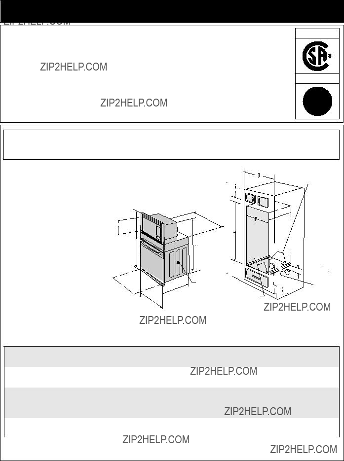
1. Carpinter??a
Consulte la Figura 1 para conocer las dimensiones pertinentes al modelo de su horno y al espacio necesario en el que poner el horno. La superficie donde se va a apoyar el horno debe de ser de madera contrachapada s??lida u otro material similar y, sobre todo, la superficie tiene que estar a nivel, de lado a lado, y de atr??s hacia adelante.
2. Requerimientos El??ctricos
Se debe proveer el voltaje y la frecuencia apropiados a este electrodom??stico, y conectarse a un circuito individual correctamente puesto a tierra, protegido por un interruptor o un fusible. Para conocer el interruptor o fusible que requiere su modelo, vea la placa serial para encontrar la consumaci??n del vatiaje y refierase al cuadro A para encontrar el amperaje del interruptor o fusible.
Table A
Observe todos los c??digos que gobiernan y ordenanzas locales
1.Un cable de 3 o 4 alambres monof??sico 120/240 o 120/208 voltios, 60 hertzios es la ??nica fuente el??ctrica que requiere en un circuito separado en ambos lados de la l??nea (alambre negro y alambre rojo) (se recomienda un fusible o un interruptor de retraso de tiempo). No funda a cable neutro (alambre blanco). Se debe de tener precauci??n al combinar un horno de pared y una cubierta, refi??rase a la placa de seria de cada uno de los aparatos.
NOTA: Los tama??os y las conexiones del alambre deben conformarse con el tama??o del fusible y el grado de la aplicaci??n de acuerdo con el c??digo El??ctrico Nacional Americano ANSI/NFPA No. 70- ultima edici??n, o con el est??ndar CSA canadiense C22.1 , c??digo el??ctrico canadiense, parte 1, y c??digos y ordenanzas locales.
 No se debera usar extensiones para enchufar este electrodom??stico. Esto podr??a causar un incendio, choque el??ctrico u otro tipo de da??o personal. Si usted necesita un cable mas largo, puede
ordernar un cable de 10" kit 903056-9010 llamando al centro de Servicio.
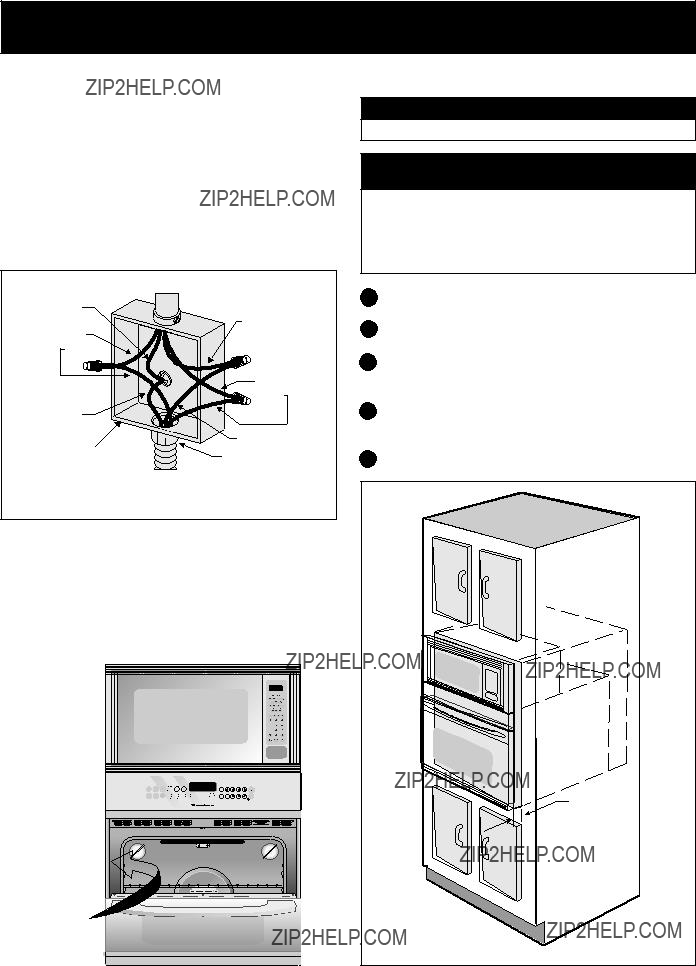
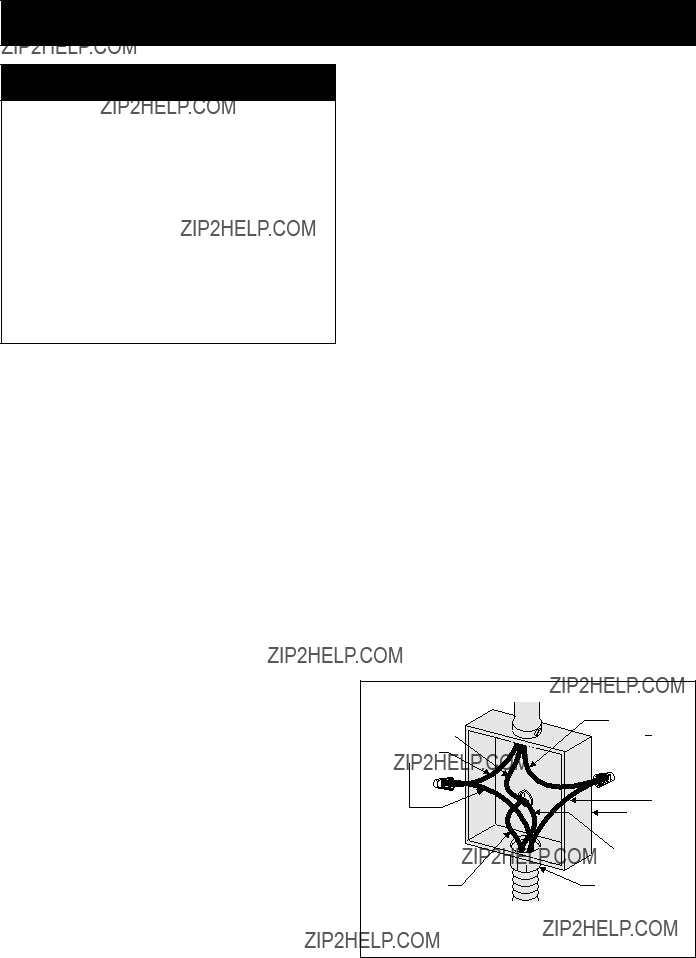
2.Este electrodom??stico debe conectarse a la caja de fusibles (o de cortocircuito), por medio de un cable blindado flexible o un cable con forro no met??lico. El cable blindado flexible que va desde el electrodom??stico debe de estar conectado directamente a la caja de empalme. La caja de empalme debe de estar localizada en el lugar que se indica en la Figura 1 o 2, dejando tanto exceso de cable como sea posible entre la caja y el electrodom??stico, de forma que as?? el electrodom??stico se pueda mover f??cilmente, si fuera necesario para hacer una reparaci??n.
3.Se debe de usar un conector que reduzca la tirantez de una forma adecuada para unir el cable blindado flexible a la caja de empalme.
 FOR YOUR SAFETY: Do not store or use gasoline or other flammable vapors and liquids in the vicinity of this or any other appliance.
 Do not remove spacers (if equipped) on the side walls and/or on the back of the built- in oven. These spacers center the oven in the space provided. The oven must be centered to prevent excess heat buildup that may result in heat damage or fire.
 Stepping, leaning or sitting on the door of this wall oven can result in serious injuries and can also cause damage to the wall oven.
 The electrical power to the oven must be shut off while line connections are being made. Failure to do so could result in serious injury or death.
 An extension cord should not be used with this appliance. Such use may result in a fire, electrical shock, or other personal injury.
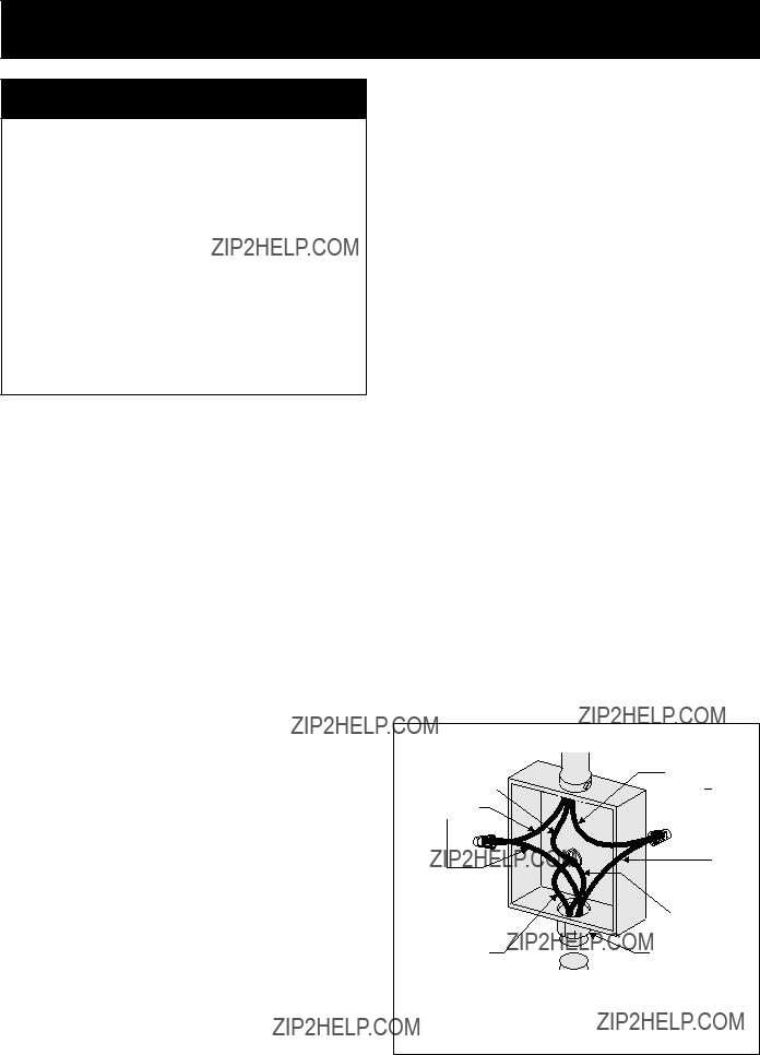
 In cold weather shipping and storage conditions, make sure that oven is in final location at least three (3) hours before switching on power.
 Risk of electrical shock (Failure to heed this warning may result in electrocution or other serious injury.) This appliance is equipped with copper lead wire. If connection is made to aluminum house wiring, use only connectors that
 (If your appliance is equipped with a white neutral conductor.)
 Junction

 The wall oven can tip when the door is open. The
 supplied


 PARA SU SEGURIDAD: No almacen?? ni utilice gasolina u otros vapores y l??quidos inflamables en la proximidad de este o de cualquier otro artefacto.
 No quite los separadores de los muros laterales o/y de la parte posterior del horno empotrado. Estos espaciadores centran el horno en el espacio provisto. El horno debe estar centrado para prevenir una concentraci??n excesiva de calor que podr??a resultar en da??os por el calor o un incendio.


 3??? (7.6 cm)
 1????? (3.2 cm)
 En cuanto a las condiciones de despacho y almacenamiento en el invierno, aseg??rese de que el horno llegue a su destino final como m??nimo tres
 Riesgo de choque el??ctrico
 (Si su electrodom??stico est?? equipado con un conductor neutro blanco.)
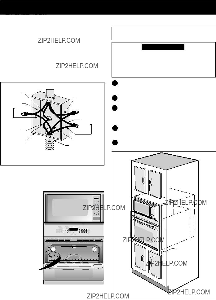
 El horno de pared puede inclinarse cuando la puerta esta abierta. Los soportes de montaje que vienen con el horno de pared deben de estar ajustadas al armario y al aparato para evitar que el horno de pared se incline y ocasione quemaduras graves.