Warnings and Caution
 WARNING
???To prevent serious injury or death from falls and being strangled in the restraint system:
-Always use the restraint sys- tem. Never rely on the tray to restrain child.
-Never use with an active child who may be able to climb out of the seat.
???Never leave child unattended.
 CAUTION
This product contains small parts in its unassembled state. Adult assembly is required.
Consumer Information
Occasionally a consumer may experience a problem with one of our products. If this should happen, please call us toll-free, rather than return this product to the store.
Usually, we can solve the problem over the telephone or send you replacement parts.
Please call Fisher-Price?? Consumer Relations, toll-free at 1-800-432-5437, 8 AM - 6 PM EST Monday through Friday. Hearing-impaired consumers using TTY/TDD equipment, please call 1-800-382-7470.
Or, write to:
Fisher-Price?? Consumer Relations 636 Girard Avenue
East Aurora, New York 14052
For other countries outside the United States:
Canada: call 1-800-567-7724, or write to: Mattel Canada Inc., 6155 Freemont Blvd., Mississauga, Ontario L5R 3W2.
Great Britain: telephone 01628 500302.
Australia: Mattel Australia Pty. Ltd., 658 Church Street, Locked Bag #870, Richmond, Victoria 3121 Australia. Consumer Advisory Service 1300 135 312.
New Zealand: 16-18 William Pickering Drive, Albany 1331, Auckland.
Asia: Mattel East Asia Ltd, Room 1106, South Tower, World Finance Centre, Harbour City, Tsimshatsui, HK, China.


 Pull
Pull
 Seat Tube


 Bracket


 Belt
Belt


 WARNING
 and
and  .
.

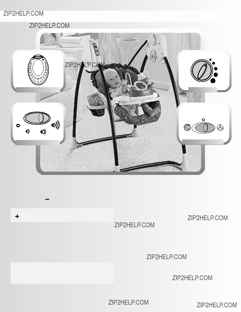

 L.E.D.

 for music highest volume.
 for music high volume.
 for music low volume.
 to turn music off.
 and back to
  baby sounds activated. The swing is now
  when not in use.

 when not in use.
 L.E.D.
 for music highest volume.
 for music high volume.
 for music low volume.
 to turn music off.
 Lights Tray
 Buttons

