12??" Portable Planer
(Model TP400LS)
PART NO. A02473 -
Copyright ?? 2004 Delta Machinery
please call
MANUAL INSTRUCTION
12??" Portable Planer
(Model TP400LS)
PART NO. A02473 -
Copyright ?? 2004 Delta Machinery
please call
MANUAL INSTRUCTION

SAFETY GUIDELINES - DEFINITIONS
This manual contains information that is important for you to know and understand. This information relates to protect- ing YOUR SAFETY and PREVENTING EQUIPMENT PROBLEMS. To help you recognize this information, we use the symbols below. Please read the manual and pay attention to these sections.
 Indicates an imminently hazardous situation which, if not avoided, will result in death or serious injury. Indicates a potentially hazardous situation which, if not avoided, could result in death or serious injury.
Indicates a potentially hazardous situation which, if not avoided, may result in minor or moderate injury.
Used without the safety alert symbol indicates potentially hazardous situation which, if not avoided, may result in property damage.
 SOME DUST CREATED BY POWER SANDING, SAWING, GRINDING, DRILLING, AND OTHER CONSTRUCTION ACTIVITIES contains chemicals known to cause cancer, birth defects or other reproductive harm. Some examples of these chemicals are:
??lead from
??crystalline silica from bricks and cement and other masonry products, and
??arsenic and chromium from
Your risk from these exposures varies, depending on how often you do this type of work. To reduce your exposure to these chemicals: work in a well ventilated area, and work with approved safety equipment, always wear MSHA/NIOSH approved, properly fitting face mask or respirator when using such tools.
GENERAL SAFETY RULES
 READ AND UNDERSTAND ALL WARNINGS AND OPERATING INSTRUCTIONS BEFORE USING THIS EQUIPMENT. Failure to follow all instructions listed below, may result in electric shock, fire, and/or serious personal injury or property damage.
IMPORTANT SAFETY INSTRUCTIONS
Woodworking can be dangerous if safe and proper operating procedures are not followed. As with all machinery, there are certain hazards involved with the operation of the product. Using the machine with respect and caution will considerably lessen the possibility of personal injury. However, if normal safety precautions are overlooked or ignored, personal injury to the operator may result. Safety equipment such as guards, push sticks,
 This machine was designed for certain applications only. Delta Machinery strongly recommends that this machine not be modified and/or used for any application other than that for which it was designed. If you have any questions relative to a particular application, DO NOT use the machine until you have first contacted Delta to determine if it can or should be performed on the product.
Technical Service Manager
Delta Machinery
4825 Highway 45 North
Jackson, TN 38305
(IN CANADA: 505 SOUTHGATE DRIVE, GUELPH, ONTARIO N1H 6M7)
2

GENERAL SAFETY RULES
 FAILURE TO FOLLOW THESE RULES MAY RESULT IN SERIOUS INJURY.
1.FOR YOUR OWN SAFETY, READ THE INSTRUCTION
MANUAL BEFORE OPERATING THE MACHINE.
Learning the machine???s application, limitations, and specific hazards will greatly minimize the possibility of accidents and injury.
2.WEAR EYE PROTECTION. ALWAYS USE SAFETY GLASSES. Also use face or dust mask if cutting operation is dusty. Everyday eyeglasses are NOT safety glasses. USE CERTIFIED SAFETY EQUIPMENT. Eye protection equipment should comply with ANSI Z87.1 standards, hearing equipment should comply with ANSI S3.19 standards, and dust mask protection should comply with MSHA/NIOSH certified respirator standards. Splinters,
3.WEAR PROPER APPAREL. Do not wear loose clothing, gloves, neckties, rings, bracelets, or other jewelry which may get caught in moving parts. Nonslip footwear is recommended. Wear protective hair covering to contain long hair.
4.DO NOT USE THE MACHINE IN A DANGEROUS ENVIRONMENT. The use of power tools in damp or wet locations or in rain can cause shock or electrocution. Keep your work area
5.MAINTAIN ALL TOOLS AND MACHINES IN PEAK CONDITION. Keep tools sharp and clean for best and safest performance. Follow instructions for lubricating and changing accessories. Poorly maintained tools and machines can further damage the tool or machine and/or cause injury.
6.CHECK FOR DAMAGED PARTS. Before using the machine, check for any damaged parts. Check for alignment of moving parts, binding of moving parts, breakage of parts, and any other conditions that may affect its operation. A guard or any other part that is damaged should be properly repaired or replaced.
Damaged parts can cause further damage to the machine and/or injury.
7.KEEP THE WORK AREA CLEAN. Cluttered areas and benches invite accidents.
8.KEEP CHILDREN AND VISITORS AWAY. Your shop is a potentially dangerous environment. Children and visitors can be injured.
9.REDUCE THE RISK OF UNINTENTIONAL STARTING.
Make sure that the switch is in the ???OFF??? position before plugging in the power cord. In the event of a power failure, move the switch to the ???OFF??? position. An accidental
10.USE THE GUARDS. Check to see that all guards are in place, secured, and working correctly to prevent injury.
11.REMOVE ADJUSTING KEYS AND WRENCHES BEFORE STARTING THE MACHINE. Tools, scrap pieces, and other debris can be thrown at high speed, causing injury.
12.USE THE RIGHT MACHINE. Don???t force a machine or
an attachment to do a job for which it was not designed. Damage to the machine and/or injury may result.
13.USE RECOMMENDED ACCESSORIES. The use of accessories and attachments not recommended by Delta may cause damage to the machine or injury to the user.
14.USE THE PROPER EXTENSION CORD. Make sure your extension cord is in good condition. When using an extension cord, be sure to use one heavy enough to carry the current your product will draw. An undersized cord will cause a drop in line voltage, resulting in loss of power and overheating. See the Extension Cord Chart for the correct size depending on the cord length and nameplate ampere rating. If in doubt, use the next heavier gauge. The smaller the gauge number, the heavier the cord.
15.SECURE THE WORKPIECE. Use clamps or a vise to hold the workpiece when practical. Loss of control of a workpiece can cause injury.
16.FEED THE WORKPIECE AGAINST THE DIRECTION OF
THE ROTATION OF THE BLADE, CUTTER, OR ABRASIVE SURFACE. Feeding it from the other direction will cause the workpiece to be thrown out at high speed.
17.DON???T FORCE THE WORKPIECE ON THE MACHINE.
Damage to the machine and/or injury may result.
18.DON???T OVERREACH. Loss of balance can make you fall into a working machine, causing injury.
19.NEVER STAND ON THE MACHINE. Injury could occur if the tool tips, or if you accidentally contact the cutting tool.
20.NEVER LEAVE THE MACHINE RUNNING UNATTENDED. TURN THE POWER OFF. Don???t leave the machine until it comes to a complete stop. A child or visitor could be injured.
21.TURN THE MACHINE ???OFF???, AND DISCONNECT THE MACHINE FROM THE POWER SOURCE before installing or removing accessories, before adjusting or changing
22.MAKE YOUR WORKSHOP CHILDPROOF WITH
PADLOCKS, MASTER SWITCHES, OR BY REMOVING STARTER KEYS. The accidental
23. STAY ALERT, WATCH WHAT YOU ARE DOING, AND
USE COMMON SENSE. DO NOT USE THE
MACHINE WHEN YOU ARE TIRED OR UNDER THE
INFLUENCE OF DRUGS, ALCOHOL, OR MEDICA- TION. A moment of inattention while operating power tools may result in injury.
24.TAKE PRECAUTIONS AGAINST DUST INHALATION.
The dust generated by certain woods and wood products can be injurious to your health. Always operate machinery in
3

ADDITIONAL SAFETY RULES FOR PLANERS
FAILURE TO FOLLOW THESE RULES MAY RESULT IN SERIOUS INJURY.
1.DO NOT OPERATE THIS MACHINE until it is completely assembled and installed according to the instructions. A machine incorrectly assembled can cause serious injury.
2.OBTAIN ADVICE from your supervisor, instructor, or another qualified person if you are not thoroughly familiar with the operation of this machine. Knowledge is safety.
3.FOLLOW ALL WIRING CODES and recommend- ed electrical connections to prevent shock or electrocution.
4.KEEP KNIVES SHARP and free from rust and pitch. Dull or rusted knives work harder and can cause kickback.
5.NEVER TURN THE MACHINE ???ON??? before clearing the table of all objects (tools, scraps of wood, etc.). Flying debris can cause serious injury.
6. NEVER TURN THE MACHINE ???ON??? with the work- piece contacting the cutterhead. Kickback can occur.
7.SECURE THE MACHINE TO A SUPPORTING SUR- FACE to prevent the machine from sliding, walking or tipping over.
8.PROPERLY SECURE THE KNIVES IN THE CUTTER- HEAD before turning the power ???ON???. Loose blades may be thrown out at high speeds causing serious injury.
9.LOCK THE SPEED SETTING SECURELY before feeding the workpiece through the machine. Changing speeds while planing can cause kick- back.
10.AVOID AWKWARD OPERATIONS AND HAND POSI- TIONS. A sudden slip could cause a hand to move into the knives.
11.KEEP ARMS, HANDS, AND FINGERS away from the cutterhead, the chip exhaust opening, and the feed rollers to prevent severe cuts.
12.NEVER REACH INTO THE CUTTERHEAD AREA while the machine is running. Your hands can be drawn into the knives.
13.DO NOT STAND IN LINE OF THE WORKPIECE.
Kickback can cause injury.
14.ALLOW THE CUTTERHEAD TO REACH FULL SPEED before feeding a workpiece. Changing speeds while planing can cause kickback.
15.WHEN PLANING BOWED STOCK, place the concave (cup down) side of the stock on the table and cut with the grain to prevent kickback.
16.DO NOT FEED A WORKPIECE that is warped, contains knots, or is embedded with foreign objects (nails, staples, etc.). Kickback can occur.
17.DO NOT FEED A SHORT, THIN, OR NARROW WORKPIECE INTO THE MACHINE. Your hands can be drawn into the knives and/or the workpiece can be thrown at high speeds. See the ???OPERATION??? section of this instruction manual for details.
18.DO NOT FEED A WORKPIECE into the outfeed end of the machine. The workpiece will be thrown out of the opposite side at high speeds.
19.REMOVE SHAVINGS ONLY with the power ???OFF??? to prevent serious injury.
20.PROPERLY SUPPORT LONG OR WIDE WORK- PIECES. Loss of control of the workpiece can cause serious injury.
21.NEVER PERFORM LAYOUT, ASSEMBLY or
22.TURN THE MACHINE ???OFF???, DISCONNECT IT FROM THE POWER SOURCE, and clean the table/work area before leaving the machine. LOCK THE SWITCH IN THE ???OFF??? POSITION to prevent un- authorized use. Someone else might accidentally start the machine and cause injury to themselves or others.
23.ADDITIONAL INFORMATION regarding the safe and proper operation of power tools (i.e. a safety video) is available from the Power Tool Institute, 1300 Sumner Avenue, Cleveland, OH
SAVE THESE INSTRUCTIONS. Refer to them often
and use them to instruct others.
4

POWER CONNECTIONS
A separate electrical circuit should be used for your machines. This circuit should not be less than #12 wire and should be protected with a 20 Amp time lag fuse. If an extension cord is used, use only
DO NOT EXPOSE THE MACHINE TO RAIN OR OPERATE THE MACHINE IN DAMP LOCATIONS.
MOTOR SPECIFICATIONS
Your machine is wired for 120V, 60 HZ alternating current. Before connecting the machine to the power source, make sure the switch is in the ???OFF??? position.
GROUNDING INSTRUCTIONS
 THIS MACHINE MUST BE GROUNDED WHILE IN USE TO PROTECT THE OPERATOR FROM
ELECTRIC SHOCK.
1. All grounded,
In the event of a malfunction or breakdown, grounding provides a path of least resistance for electric current to reduce the risk of electric shock. This machine is equipped with an electric cord having an equipment- grounding conductor and a grounding plug. The plug must be plugged into a matching outlet that is properly installed and grounded in accordance with all local codes and ordinances.
Do not modify the plug provided - if it will not fit the outlet, have the proper outlet installed by a qualified electrician.
Improper connection of the
Check with a qualified electrician or service personnel if the grounding instructions are not completely understood, or if in doubt as to whether the machine is properly grounded.
Use only
Repair or replace damaged or worn cord immediately.
GROUNDED OUTLET BOX
CURRENT
CARRYING
PRONGS
2. Grounded,
If the machine is intended for use on a circuit that has an outlet that looks like the one illustrated in Fig. A, the machine will have a grounding plug that looks like the plug illustrated in Fig. A. A temporary adapter, which looks like the adapter illustrated in Fig. B, may be used to connect this plug to a matching
NOTE: In Canada, the use of a temporary adapter is not permitted by the Canadian Electric Code.
 IN ALL CASES, MAKE CERTAIN THE
R E C E P TA C L E I N Q U E S T I O N I S P R O P E R LY
GROUNDED. IF YOU ARE NOT SURE HAVE A
QUALIFIED ELECTRICIAN CHECK THE RECEPTACLE.
GROUNDED OUTLET BOX
GROUNDING
MEANS
ADAPTER
GROUNDING BLADE
IS LONGEST OF THE 3 BLADES

EXTENSION CORDS
 Use proper extension cords. Make sure your extension cord is in good condition and is a
MINIMUM GAUGE EXTENSION CORD
RECOMMENDED SIZES FOR USE WITH STATIONARY ELECTRIC MACHINES
Fig.
MINIMUM GAUGE EXTENSION CORD
RECOMMENDED SIZES FOR USE WITH STATIONARY ELECTRIC MACHINES
Fig.
6

FUNCTIONAL DESCRIPTION
FOREWORD
Delta ShopMaster Model TP400LS is a 12??" (317mm) Portable Planer. This planer can handle workpieces up to 12??" (317mm) wide and 6" (152mm) thick. The maximum depth of cut is 3/32" (3mm). The features include basic machine with powerful 15 amp, 120 volt motor,
UNPACKING AND CLEANING
Carefully unpack the machine and all loose items from the shipping container. Peel protective film from the table surface. Figures 1 and 2 illustrate the planer and all loose items supplied with your machine. Refer to the section of this manual entitled ???REPLACING KNIVES??? and remove the cutterhead guard. Remove the protective coating from the cutterhead. This coating may be removed with a soft cloth moistened with kerosene (do not use acetone, gasoline or lacquer thinner for this purpose.) CAUTION: CARE MUST BE TAKEN WHEN CLEANING THE CUTTERHEAD, THE KNIVES IN THE CUTTERHEAD ARE VERY SHARP. After cleaning cutterhead, replace the cutterhead guard.
NOTICE: THE PHOTO ON THE MANUAL COVER ILLUSTRATES THE
CURRENT PRODUCTION MODEL. ALL OTHER ILLUSTRATIONS CONTAINED
IN THE MANUAL ARE REPRESENTATIVE ONLY AND MAY NOT DEPICT THE
ACTUAL COLOR, LABELING OR ACCESSORIES AND ARE INTENDED TO
ILLUSTRATE TECHNIQUE ONLY.
7

PLANER PARTS
1
1- 12??" Portable Planer
2- Cutterhead raising and lowering handle
3- M5x.8x20mm hex socket head screw
4- Cutterhead lock handle
5- M6x20mm specia hex socket head screw
Fig. 2
ASSEMBLY
FOR YOUR OWN SAFETY, DO NOT CONNECT THE MACHINE TO THE POWER SOURCE UNTIL
THE MACHINE IS COMPLETELY ASSEMBLED AND YOU READ AND UNDERSTAND THE ENTIRE INSTRUCTION
MANUAL.
8
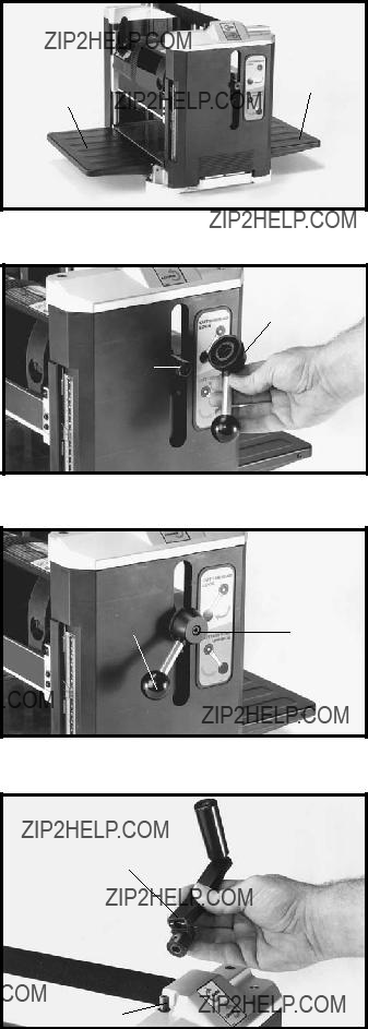
LOWERING
EXTENSION TABLES
The infeed and outfeed table extensions (A) Fig. 4, are shipped attached to the machine in the ???UP??? position. Rotate both table extensions to the down position as shown. The top surface of the table extensions should be level with the planer table. To check and adjust if necessary, refer to the section of this manual entitled
???LEVELING TABLE EXTENSIONS.???
CUTTERHEAD
LOCK HANDLE
1. Assemble the cutterhead lock handle (A) Fig. 5, to shaft (B).
2. Fasten cutterhead lock handle (A) Fig. 6, to the shaft using the M6x20mm special hex socket head screw (C), with wrench supplied.
CUTTERHEAD RAISING AND
LOWERING HANDLE
1. Assemble the cutterhead raising and lowering handle
(A) Fig. 7, to shaft (B), making certain flat on shaft is engaged with flat in handle.
A
A
Fig. 4
A
B
Fig. 5
AC
Fig. 6
A
B
Fig. 7
9

2. Fasten cutterhead raising and lowering handle (A) Fig. 8, to shaft using the M5x.8x20mm hex socket head screw (C) with wrench supplied.
3. Rotate handle (A) to the operating position as shown in Fig. 9, and tighten set screw (D).
FASTENING PLANER TO STAND
Place the planer on the stand and align the four holes in the base of the machine, two of which are shown at (A) Fig. 10, with the four holes in the top of the stand. Place the M8x1.25x35mm hex head flange bolt through the holes in the planer and the stand, and thread the M8x1.25 flange nut onto the hex head flange bolt and tighten securely. Only operate planer, attached to stand, on a flat level surface.
 C
C
 A
A
Fig. 8
A
D
Fig. 9
A
A
Fig. 10
10
OPERATING CONTROLS AND ADJUSTMENTS
STARTING AND
STOPPING PLANER
The on/off switch (A) Fig. 14, is located on the front of the planer motor. To turn the machine ???ON??? move the switch up to the ???ON??? position. To turn the machine ???OFF??? move the switch down to the ???OFF??? position.
LOCKING SWITCH IN
THE ???OFF??? POSITION
When the tool is not in use, the switch should be locked in the ???OFF??? position to prevent unauthorized use. This can be done by grasping the switch toggle (B) Fig. 15, and pulling it out of the switch, as shown. With the switch toggle removed, the switch will not operate. However, should the switch toggle be removed while the machine is running, the switch can be turned ???OFF??? once, but cannot be restarted without inserting the switch toggle.
A
Fig. 14
B
Fig. 15
RAISING AND LOWERING
HEAD ASSEMBLY
The head assembly (A) Fig. 16, contains the cutterhead, feed rollers, chip deflector and motor. Raising and lowering the head assembly controls the depth of cut. To raise or lower the head assembly, rotate the cutterhead lock handle (B) counterclockwise to unlock the cutterhead and turn the cutterhead raising and lowering handle (C) clockwise to raise or counterclockwise to lower the cutterhead. One revolution of handle will move the cutterhead up or down 3/32".
ALWAYS LOCK THE CUTTERHEAD IN PLACE, BY
ROTATING HANDLE (B) CLOCKWISE BEFORE
PLANING.
SCALE AND POINTER
A dual English/Metric scale (D) Fig. 17, and pointer (E) is conveniently located on the front of the machine and in- dicates the thickness of the finished workpiece. Adjust- ment to the pointer can be made by running a piece of wood through the machine. Measure the thickness of the workpiece and if an adjustment is necessary, loosen two screws (F) and adjust pointer accordingly. Then tighten two screws.
C
A
B
Fig. 16
 D
D
E
F
Fig. 17
11

RECOMMENDED
DEPTH OF CUT
NOTE: One revolution of the raising and lowering handle will move the cutterhead up or down 3/32 of an inch.
A 3/32" depth of cut can be made in soft woods on stock up to 8" wide and in hard woods on stock up to 7" wide; see chart in Fig. 18.
For 10" and 12" wide soft wood, we recommend a maxi- mum depth of cut of 1/16". For 10" and 12" wide hard wood, a maximum depth of cut of 3/64" is recommended; see chart in Fig. 18.
LEVELING
TABLE EXTENSIONS
The table extensions, one of which is shown at (A) Fig. 19, must be level with the planer table. To check and adjust if necessary, proceed as follows:
 DISCONNECT MACHINE FROM POWER
SOURCE.
1.Place a straight edge (B) Fig. 19, on the planer table with one end of the straight edge extending out over the infeed table extension (A) as shown. Check to see if the table extension is level with the planer table on both ends of table extension.
2.If an adjustment is necessary, loosen locknut (D) and adjust stop screw (E) on each end of the table (A) until table extension is level with planer table. Then tighten locknut. Recheck and make certain inside edge of table extension is level with planer table. NOTE: If necessary, loosen two screws (C), adjust table extension and tighten two screws.
3.Adjust opposite end of table extension (A) in the same manner. Make sure table is solidly supported in the level position.
4.Check and adjust outfeed table extension in the same manner.
Fig. 18
B
12

KNIFE TRANSFER TOOL
STORAGE
1.The knife transfer tool (A) Fig. 20, supplied with your planer, can easily be stored underneath the outfeed table extension (B) when not being used. A Velcro strip
(C) is provided on the tool and underneath the table for this purpose.
2.Figure 21 illustrates the knife transfer tool (A) stored underneath the outfeed table extension.
B
C
A
C
WRENCH STORAGE
The wrench (A) Fig. 21, can be stored in hole (B) located on the right rear side of the machine as shown.
Fig. 20
A
B
Fig. 21
13

A
A
CARRYING HANDLE/STOCK TRANSFER BAR
1.Your planer is provided with a foam covered carrying handle (A) Fig. 22, located on top of the machine, for ease in transporting the planer. Carrying handles are also provided at the base of the planer on each side which allow you to lift the machine with ease.
2.The carrying handle (A) Fig. 23, also doubles as a stock transfer bar for transferring stock from the outfeed to infeed end of the machine. This is helpful when planing long material, as the workpiece can easily be transferred back to the infeed end of the machine for additional cuts.
REPLACING KNIVES
The knives supplied with your planer are double edged and reversible, which enables you to turn the knives
DISCONNECT MACHINE FROM POWER
SOURCE.
1. Raise head assembly all the way to the top.
THE KNIVES ARE SHARP.
B
Fig. 24
3.Figure 26 illustrates the cutterhead guard removed, exposing the cutterhead (C).
4.Using the wrench supplied, rotate cutterhead by inserting end of wrench into the hex hole (A) Fig. 25. Rotate cutterhead until the cutterhead lock (D) Fig. 26, engages and locks the cutterhead (C) in place.
A
Fig. 25
14
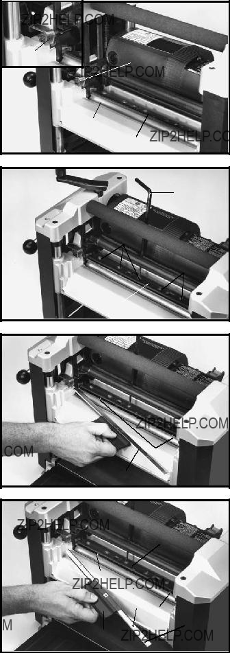
5. Figure 26 illustrates the cutterhead (C) locked in place allowing access to the knife locking bar (E).
6. Using the supplied wrench (E) Fig. 27, unscrew the six screws, five of which are shown at (F), only enough until locking bar (D) separates from knife, allowing knife to be removed.
7. Insert knife transfer tool (G) Fig. 28, underneath center of knife. Lift the knife transfer tool up until knife
(H) separates from pins (J) and pull out and remove knife as shown. NOTE: Knife transfer tool is magnetized, allowing it to attach to knife.
8. Rotate knife (H) Fig. 29,
C
E
Fig. 26
E
F
F
D
Fig. 27
G
J
H
Fig. 28
D
K J
J
K
J
H
G
Fig. 29
15

9.Remove knife transfer tool and tighten the six screws, five of which are shown at (F) Fig. 30, using wrench (E) supplied.
10.Replace other knife by rotating head 180 degrees and repeat STEPS 5 THROUGH 10.
11. Replace cutterhead guard (B) Fig. 31, making sure cutterhead lock (D) is depressed and underneath guard as shown. Slide guard in as far as possible and replace two screws, one of which is shown at (A) Fig. 32. These screws were removed in STEP 3.
ADJUSTING HEIGHT
OF OUTFEED ROLLER
DISCONNECT MACHINE FROM
POWER SOURCE.
1. The outfeed roller is adjusted at the factory to be 0.020" below the cutting circle. In order to check and adjust the outfeed roller, you will need a homemade gage block made of hardwood. This gage block can be constructed by following the dimensions shown in Fig. 33. NOTE: Make sure that the height of the block is exactly 4 ".
E
DF
F
Fig. 30
D
B
Fig. 31
A
Fig. 32
4"
1/ " 4
2" 1/2"3" 4"
Fig. 33
16

2.Make sure the knives are inserted into the cutterhead properly, as explained under ???REPLACING KNIVES.???
3.Place the gage block (A) Fig. 34, on the table, over a 0.020" feeler gage and position the gage block (A) directly underneath the cutterhead. Raise or lower the head assembly and rotate the cutterhead, by following STEP
5under ???REPLACING KNIVES,??? until one of the knives
(B) just touches the top of the gage block when the knife is at its lowest point. Then tighten cutterhead lock handle.
4.Move the gage block (A) Fig. 35, minus the feeler gage, under one end of the outfeed roller (C) as shown. The bottom of the outfeed roller should just touch the top of the gage block.
5.If the height of the outfeed roller must be adjusted, loosen locknut (D) Fig. 35, and turn adjusting screw (E) until outfeed roller just touches the gage block (A). Tighten locknut after adjustment is made.
6.Repeat this adjustment on opposite end of outfeed roller (C) Fig. 35.
B
A
Fig. 34
D
E
D
E
C
A
Fig. 35
OPERATION
When using your machine, you may want to follow these few simple steps for achieving the best results possible.
1.True Up One Face ??? Feed one face of the board over a jointer, making thin cuts with each pass, until the entire surface is flat.
2.Plane to Thickness ??? Place the side you just surfaced in STEP 1 face down and feed the board through the planer, plane until this side is flat. Then plane both sides of the board until you are satisfied with the thickness, making thin cuts, alternating sides with each pass. If during the planing operation you notice the board twisting, warping or bowing, repeat STEP 1 and true up one face.
3.When planing long stock, provide table extensions to support the infeed and outfeed end of the workpiece.
4.For best results, always engage cutterhead lock before planing, plane with the grain only, and keep planer table clean. Occasionally, wax table surface to reduce friction during the planing operation.
5.
NOTE: THE KNIVES ON THE PLANER WILL NOT WEAR EVENLY IF THE WOOD IS FED THROUGH THE SAME
SPOT ON THE TABLE EVERY TIME. FEED THE WOOD THROUGH THE PLANER AT DIFFERENT SPOTS ON THE
TABLE WHEN POSSIBLE, TO HELP ELIMINATE UNEVEN WEAR OF THE KNIVES.
17

MAINTENANCE
BRUSH INSPECTION
AND REPLACEMENT
DISCONNECT MACHINE FROM POWER
SOURCE.
Brush life varies. It depends on the load on the motor. Check the brushes after the first 50 hours of use for a new machine or after a new set of brushes has been installed. After the first check, examine them after about every 10 hours of use until replacement is necessary.
The brush holders, one of which is shown at (A) Fig. 36, are located on the motor housing opposite each other. Fig. 37, illustrates one of the brushes removed for in- spection. When the carbon (B) on either brush is worn to 3/16" in length or if either spring (C) or shunt wire is burned or damaged in any way, replace both brushes. If the brushes are found serviceable after removing, re- install them in the same position as removed.
LUBRICATION
The gears in the gear box and the feed roller bushings should be lubricated periodically, as follows:
A
Fig. 36
C
B
DISCONNECT MACHINE FROM
POWER SOURCE.
1.Remove two screws (A) Fig. 38, located on bottom of left side cover (B) of planer, and remove left side cover.
2.Place extreme pressure lithium grease on the teeth of gears (C) Fig. 39, and replace the side cover.
3.Lay the planer on its back and squirt oil on the feed roller bushings (D) Fig. 40, at each end of the feed rollers.
Fig. 37
 B
B
A
Fig. 38
18

NOTES
19

ACCESSORIES
A complete line of accessories is available from your Delta Supplier,
 Since accessories other than those offered by Delta have not been tested with this product, use of such accessories could be hazardous. For safest operation, only Delta recommended accessories should be used with this product.
PARTS, SERVICE OR WARRANTY ASSISTANCE
All Delta Machines and accessories are manufactured to high quality standards and are serviced by a network of
Two Year Limited New Product Warranty
Delta will repair or replace, at its expense and at its option, any new Delta machine, machine part, or machine accessory which in normal use has proven to be defective in workmanship or material, provided that the customer returns the product prepaid to a Delta factory service center or authorized service station with proof of purchase of the product within two years and provides Delta with reasonable opportunity to verify the alleged defect by inspection. For all refurbished Delta product, the warranty period is 180 days. Delta may require that electric motors be returned prepaid to a motor manufacturer???s authorized station for inspection and repair or replacement. Delta will not be responsible for any asserted defect which has resulted from normal wear, misuse, abuse or repair or alteration made or specifically authorized by anyone other than an authorized Delta service facility or representative. Under no circumstances will Delta be liable for incidental or consequential damages resulting from defective products. This warranty is Delta???s sole warranty and sets forth the customer???s exclusive remedy, with respect to defective products; all other warranties, express or implied, whether of merchantability, fitness for purpose, or otherwise, are expressly disclaimed by Delta.
20
(CENTROS DE SERVICIO DE
Parts and Repair Service for
Authorized Service Stations are located in many large cities. Telephone
CANADIAN
The following are trademarks of
Trademarks noted with ??? and ?? are registered in the United States Patent and Trademark Office and may also be registered in other countries. Las Marcas Registradas con el signo de ??? y ?? son registradas por la Oficina de Registros y Patentes de los Estados Unidos y tambi??n pueden estar