The
F-25/30/35/40 & 45
Combination Heaters
- Input from 100,000 to 199,000 Btu/hr -
* I N S T A L L A T I O N A N D M A I N T E N A N C E *
M A N U A L
Warranty Registration Card must be filled out by the customer and mailed within thirty (30) days of installa- NOTICE tion in order to gain warranty coverage.
When receiving Triangle Tube units, any claims for damage or shortage in shipment must be filed immedi- ately against the transportation company by the consignee.
Leave all documentation received with appliance with owner for future reference.
WARNING If the information in this manual is not followed exactly, a fire or explosion may result causing property damage, personal injury or death.
For Your Safety
???Do not store or use gasoline or other flammable vapors and liquids in the vicinity of this or any other appliance.
???WHAT TO DO IF YOU SMELL GAS
-Do not try to light any appliance
-Do not touch any electrical switch; do not use any phone in your building.
-Immediately call your gas supplier from a neighbor???s phone. Follow the gas supplier???s instructions.
-If you cannot reach your gas supplier, call the fire department.
Installation and service must be performed by a qualified installer, service agency or the gas supplier
2004-7 Delta Elite Manual
Table of Contents
PRODUCT AND SAFETY INFORMATION
Definitions . . . . . . . . . . . . . . . . . . . . . . . . . . . . . . . . . . . . . . . . . . . . . . . . 1
Product Warnings . . . . . . . . . . . . . . . . . . . . . . . . . . . . . . . . . . . . . . . . . . . 2-3
Operating Restrictions . . . . . . . . . . . . . . . . . . . . . . . . . . . . . . . . . . . . . . . 4
Code Restrictions . . . . . . . . . . . . . . . . . . . . . . . . . . . . . . . . . . . . . . . . . . . 4
SECTION I - PRE-INSTALLATION ITEMS
Code Compliance . . . . . . . . . . . . . . . . . . . . . . . . . . . . . . . . . . . . . . . . . . . 5
Determining Product Location . . . . . . . . . . . . . . . . . . . . . . . . . . . . . . . . . 5
Boiler Replacement . . . . . . . . . . . . . . . . . . . . . . . . . . . . . . . . . . . . . . . . . 5
Recommended Clearances . . . . . . . . . . . . . . . . . . . . . . . . . . . . . . . . . . . . 5-6
Flooring and Foundation. . . . . . . . . . . . . . . . . . . . . . . . . . . . . . . . . . . . . . 6
Residential Garage Installations . . . . . . . . . . . . . . . . . . . . . . . . . . . . . . . . 6
SECTION II - COMBUSTION AIR AND VENTING
Providing Air for Combustion and Ventilation . . . . . . . . . . . . . . . . . . . . . 7-8 Removal of an Existing Boiler from a Common Vent . . . . . . . . . . . . . . . . 8
SECTION III - UNIT PREPARATION
Handling Instructions . . . . . . . . . . . . . . . . . . . . . . . . . . . . . . . . . . . . . . . . 9
Hydrostatic Pressure Test
Hydrostatic Test Preparation . . . . . . . . . . . . . . . . . . . . . . . . . . . . . 9
Hydrostatic Test Procedures . . . . . . . . . . . . . . . . . . . . . . . . . . . . . 9-10
Completion of Hydrostatic Test and Draining . . . . . . . . . . . . . . . . 10
SECTION IV - DOMESTIC PIPING
General Piping Requirements . . . . . . . . . . . . . . . . . . . . . . . . . . . . . . . . . . 11
Domestic Supply Pressure . . . . . . . . . . . . . . . . . . . . . . . . . . . . . . . . . . . . 11
Thermal Expansion. . . . . . . . . . . . . . . . . . . . . . . . . . . . . . . . . . . . . . . . . . 11
Water Hammer . . . . . . . . . . . . . . . . . . . . . . . . . . . . . . . . . . . . . . . . . . . . . 11
Temperature / Pressure Relief Valve . . . . . . . . . . . . . . . . . . . . . . . . . . . . . 11-12
Thermostatic Mixing Valve. . . . . . . . . . . . . . . . . . . . . . . . . . . . . . . . . . . . 12
i
Table of Contents
U-Tube Assembly. . . . . . . . . . . . . . . . . . . . . . . . . . . . . . . . . . . . . . . . . . . 12-13
Domestic Drain Valve. . . . . . . . . . . . . . . . . . . . . . . . . . . . . . . . . . . . . . . . 13
Multiple Units Installation . . . . . . . . . . . . . . . . . . . . . . . . . . . . . . . . . . . . 13
Storage Tank Application . . . . . . . . . . . . . . . . . . . . . . . . . . . . . . . . . . . . . 13
TR/Smart Series Application. . . . . . . . . . . . . . . . . . . . . . . . . . . . . . . . . . . 14
Domestic Piping Diagrams . . . . . . . . . . . . . . . . . . . . . . . . . . . . . . . . . . . . 14-16
SECTION V - PRIMARY PIPING
General Piping Requirements
Low Water Cut-off Device . . . . . . . . . . . . . . . . . . . . . . . . . . . . . . 17 Backflow Preventer. . . . . . . . . . . . . . . . . . . . . . . . . . . . . . . . . . . . 17 Primary System Piping Applications. . . . . . . . . . . . . . . . . . . . . . . . . . . . . 17
Expansion Tank and Makeup Water
Diaphragm (Bladder) Expansion Tank. . . . . . . . . . . . . . . . . . . . . . 17 Closed-Type (Standard) Expansion Tank . . . . . . . . . . . . . . . . . . . . 17 Circulator . . . . . . . . . . . . . . . . . . . . . . . . . . . . . . . . . . . . . . . . . . . . . . . . . 18 Closet (Zero Clearance) Applications . . . . . . . . . . . . . . . . . . . . . . . . . . . . 18 Sizing Primary Piping. . . . . . . . . . . . . . . . . . . . . . . . . . . . . . . . . . . . . . . . 18 System Piping - Zone Circulators . . . . . . . . . . . . . . . . . . . . . . . . . . . . . . . 18 System Piping - Zone Valves . . . . . . . . . . . . . . . . . . . . . . . . . . . . . . . . . . 18
System Piping - Radiant Heating with Mixing Valves. . . . . . . . . . . . . . . . 18-19 System Piping - Multiple Units Installation. . . . . . . . . . . . . . . . . . . . . . . . 19 Primary Piping Diagrams . . . . . . . . . . . . . . . . . . . . . . . . . . . . . . . . . . . . . 20-23
SECTION VI - VENTING
General Requirements. . . . . . . . . . . . . . . . . . . . . . . . . . . . . . . . . . . . . . . . 24
Oil Vent Piping. . . . . . . . . . . . . . . . . . . . . . . . . . . . . . . . . . . . . . . . . . . . . 24-25
Oil Vent -Direct Vent Applications . . . . . . . . . . . . . . . . . . . . . . . . . . . . . . 25
Gas Venting - General Requirements . . . . . . . . . . . . . . . . . . . . . . . . . . . . 26
Masonry and Metal Chimneys . . . . . . . . . . . . . . . . . . . . . . . . . . . . . . . . . 26
Type B Vent Systems . . . . . . . . . . . . . . . . . . . . . . . . . . . . . . . . . . . . . . . . 26
Vent Connectors . . . . . . . . . . . . . . . . . . . . . . . . . . . . . . . . . . . . . . . . . . . . 27
Common Vent System . . . . . . . . . . . . . . . . . . . . . . . . . . . . . . . . . . . . . . . 27
SECTION VII - FUEL PIPING
Gas Supply Piping Connection . . . . . . . . . . . . . . . . . . . . . . . . . . . . . . . . . 28 Pipe sizing -Natural Gas . . . . . . . . . . . . . . . . . . . . . . . . . . . . . . . . . . . . . . 29 Natural Gas Supply Pressure Requirements . . . . . . . . . . . . . . . . . . . . . . . 29
ii
Table of Contents
Pipe Sizing - Propane Gas . . . . . . . . . . . . . . . . . . . . . . . . . . . . . . . . . . . . 30
Propane Gas Supply Pressure Requirements . . . . . . . . . . . . . . . . . . . . . . . 30
General Oil Piping Guidelines . . . . . . . . . . . . . . . . . . . . . . . . . . . . . . . . . 30
SECTION VIII - INTERNAL WIRING
General Requirements. . . . . . . . . . . . . . . . . . . . . . . . . . . . . . . . . . . . . . . . 31
Internal Control Wiring Diagrams. . . . . . . . . . . . . . . . . . . . . . . . . . . . . . . 31-32
SECTION IX - EXTERNAL WIRING
Installation Compliance . . . . . . . . . . . . . . . . . . . . . . . . . . . . . . . . . . . . . . 33
Line Voltage Connections . . . . . . . . . . . . . . . . . . . . . . . . . . . . . . . . . . . . . 33
Thermostat Wiring . . . . . . . . . . . . . . . . . . . . . . . . . . . . . . . . . . . . . . . . . . 33
Outdoor Temperature Limit . . . . . . . . . . . . . . . . . . . . . . . . . . . . . . . . . . . 33
External Control Wiring Diagrams . . . . . . . . . . . . . . . . . . . . . . . . . . . . . . 34-36
SECTION X - START-UP PREPARATION
Check System and Domestic Water Chemistry
Water pH Level 6.0 to 8.0 . . . . . . . . . . . . . . . . . . . . . . . . . . . . . . . 37 Water Hardness Less Than 7 Grains . . . . . . . . . . . . . . . . . . . . . . . 37 Chloride Concentration Less Than 80mg/L . . . . . . . . . . . . . . . . . . 37 Chlorinated Water . . . . . . . . . . . . . . . . . . . . . . . . . . . . . . . . . . . . . 37 Flush Primary and Domestic System. . . . . . . . . . . . . . . . . . . . . . . . . . . . . 37
Check and Test Antifreeze . . . . . . . . . . . . . . . . . . . . . . . . . . . . . . . . . . . . 37 Use of Antifreeze in the Primary System . . . . . . . . . . . . . . . . . . . . . . . . . 38 Filling the Inner (Domestic) Tank and System . . . . . . . . . . . . . . . . . . . . . 38 Filling the Outer (Primary) Tank and System . . . . . . . . . . . . . . . . . . . . . . 38-39 Check Low Water Cut-off Device . . . . . . . . . . . . . . . . . . . . . . . . . . . . . . 39 Check for Gas Leaks . . . . . . . . . . . . . . . . . . . . . . . . . . . . . . . . . . . . . . . . 39 Check Thermostat Circuit . . . . . . . . . . . . . . . . . . . . . . . . . . . . . . . . . . . . . 39
SECTION XI - START-UP PROCEDURES
Final Checks Before Start-up . . . . . . . . . . . . . . . . . . . . . . . . . . . . . . . . . . 40
ELITE Start-up. . . . . . . . . . . . . . . . . . . . . . . . . . . . . . . . . . . . . . . . . . . . . 40-41
iii
Table of Contents
SECTION XII - TEMPERATURE LIMITS
Setting Primary Thermostat Limit. . . . . . . . . . . . . . . . . . . . . . . . . . . . . . . 42
Adjustment of Secondary Thermostat Limit . . . . . . . . . . . . . . . . . . . . . . . 42
Setting the Thermostatic Mixing Valve . . . . . . . . . . . . . . . . . . . . . . . . . . . 43
SECTION XIII - CHECK-OUT PROCEDURES
Check-out Procedures. . . . . . . . . . . . . . . . . . . . . . . . . . . . . . . . . . . . . . . . 44
SECTION XIV - INSTALLATION RECORD
Installation Record . . . . . . . . . . . . . . . . . . . . . . . . . . . . . . . . . . . . . . . . . . 45
SECTION XVII - REPLACEMENT PARTS
Replacement Parts . . . . . . . . . . . . . . . . . . . . . . . . . . . . . . . . . . . . . . . . . . 46-49
PRODUCT SPECIFICATIONS
Specifications . . . . . . . . . . . . . . . . . . . . . . . . . . . . . . . . . . . . . . . . . . . . . . 50-51
iv
Product & Safety Information
The following terms are used throughout this manual to bring attention to the presence of potential hazards or to important information concerning the product.
Indicates the presence of a hazardous situation which, if ignored, will result in death, serious injury or substantial property damage.
Indicates special instructions on instal- lation, operation or maintenance, which are important to equipment but not related to personal injury hazards.
WARNING
Indicates a potentially hazardous situ- ation which, if ignored, can result in death, serious injury or substantial property damage.
CAUTION
Indicates a potentially hazardous situ- ation which, if ignored, may result in minor injury or property damage.
BEST PRACTICES
Indicates recommendations made by Triangle Tube for the installers which will help to ensure optimum operation and longevity of the equipment
NOTICE
Triangle Tube reserves the right to modify the technical specifications and components of its products without prior notice.
1
Product & Safety Information
WARNING
Bacteria can develop in the domestic water system if certain minimum water temperatures are not maintained.
DANGER
Water temperature over 125??F can cause severe burns instantly or death from scalds.
???Children, disabled and elderly are at highest risk of being scalded.
-Never leave them unattended in or near shower, bathtub or sink.
-Never allow small children to use a hot water faucet or draw their own bath.
???If any one using hot water in the building fits this description or codes require spe- cific water temperatures at hot water faucet, we recommend:
a)ensure the factory installed thermosta- tic mixing valve is working properly.
b)to set the thermostatic mixing valve for the lowest temperature which sat- isfies your hot water need.
CAUTION
.
Protection must be taken against excessive temperature and pressure!
TO PROTECT AGAINST EXCESSIVE
TEMPERATURE AND PRESSURE
???Check if the Temperature and Pressure (T&P) relief valve is in the location provided. (Domestic Water)
???Check if the 30 psi relief valve sup- plied is in the location provided. (Primary water)
???To avoid injury, install the relief devices to comply with local code requirements.
Product & Safety Information
Do not use this appliance if any part has been under water. Immediately call a qualified service technician to inspect the appliance and to replace any part of the control system which has been under water.
DANGER
WHAT TO DO IF YOU SMELL GAS - Do not try to light any appliance
Should overheating occur or the gas supply fails to shut off, turn OFF the manual gas control valve external to the appliance.
CAUTION
To prevent damage to inner tank, installer must:
-Do not touch any electrical switch; do not use any phone in your building.
-Immediately call your gas supplier from a neighbor???s phone. Follow the gas supplier???s instructions.
-If you cannot reach your gas suppli- er, call the fire department.
Installation and service must be per- formed by a qualified installer, service agency or the gas supplier.
???Fill inner tank prior to outer tank during start-up.
???Relieve primary system pressure below 15 psig prior to draining inner tank.
fittings not specified by Triangle Tube.
-This product should be maintained / ser- viced and inspected annually by a qual- ified service technician.
- This manual is intended for use by a qualified Installer/Service Technician.
3
Product & Safety Information
OPERATING RESTRICTIONS
???Maximum working pressure for inner (domestic water) tank is 150 psig.
???Maximum working pressure for outer (primary water) tank is 45 psig.
???Inner tank has factory installed Temperature & Pressure Relief Valve with an AGA rating of 100,000 Btu/hr for PG-25 and 200,000 Btu/hr for PG- 30/35/40/45.
???Outer tank has a factory installed 30 psig relief valve rated at 535,000 Btu/hr
???Electrical rating:120 V, 60 Hz, less than 12 amperes
???pH & chloride limits for the ELITE are:
-Chloride, less than 80 mg/l.
-pH, 6.0 - 8.0.
NOTICE
Any water conditioning system must be installed and maintained in accordance with manufacturer???s specifications.
???180?? Maximum operating temperature - primary side.
???120?? Maximum outlet/mixed tempera- ture - domestic side.
CODE RESTRICTIONS
Single wall heat exchanger in the ELITE complies with National Standard Plumbing Code, provided that:
-Outer tank water (including additives) is practically non-toxic, having toxicity rating or Class of 1, as listed in Clinical Toxicology of Commercial Products,
-Outer tank pressure is limited to maxi- mum 30 psig by approved relief valve.
Single wall heat exchangers are permitted under the Uniform Plumbing code - Paragraph L3.2. if they satisfy all of the following requirements.
1.The heat transfer medium is potable water or contains only substances which are recognized as safe by the U.S. Food and Drug Administration.
2.The pressure of the heat transfer medium is maintained less than the normal mini- mum operating pressure of the potable water system
3.The equipment is permanently labeled to indicate that only additives recog- nized as safe by the FDAshall be used in the heat transfer medium.
Or, per Uniform Plumbing Code paragraph L3.3 as follows:
Other heat exchanger designs may be permitted where approved by the Administrative Authority.

SECTION I - Pre-Installation Items
Code Compliance
This product must be installed in accor- dance to the following:
???All applicable local, state, national and provincial codes, ordinances, regula- tions and laws.
???The National Fuel Gas Code NFPA54/ ANSI Z332.1 - Latest edition.
???Installation of Oil Burning Equipment NFPA 31 - Latest Edition
???National Electric Code ANSI/NFPA 70.
???For installations in Canada -???Installation Code for Gas Burning Equipment??? CGA/B149.
???For installations in Canada - Installation code for Oil Burning Equipment - CSA/B139.
Determining Product Location
Before locating the ELITE check for conve- nient locations to:
-Domestic water supply piping
-Heating system piping
-Venting
-Gas or oil supply piping
-Electrical service
Ensure the area chosen for the installation of the ELITE is free of any combustible materials, gasoline and other flammable liquids.
WARNING
Failure to remove or maintain the area free of combustible materials, gasoline and other flammable liquids or vapors can result in severe personal injury, death or substantial property damage.
Ensure the ELITE and its controls are protect- ed from dripping or spraying water during nor- mal operation or service.
The ELITE should be installed in a location so that any water leaking from the tank or piping connections or relief valves will not cause damage to the area surrounding the unit or any lower floors in the structure.
-When such a location is unavoidable a suitable drain pan with adequate drainage should be placed under the unit. The drain pan must not restrict the flow of combustion air to the unit.
Boiler Replacement
If the ELITE is replacing an existing boiler / hot water heater system, the following items should be checked and corrected prior to instal- lation:
???Primary and domestic piping leaks and corrosion.
???Improper location and sizing of the expansion tank on the primary heating loop.
???Improper sizing of the thermal expan- sion tank (if used) on the domestic sup- ply line.
???Vent condition and sizing.
Recommended Clearances
The ELITE is approved for zero clearance to combustibles, excluding the vent hood and vent piping.
Vent hood and vent piping - 6 inches from combustible materials when using type ???L??? double wall vent.
Vent Piping - 18 inches from combustible materials when using single wall vent.
Primary and domestic hot water piping - 1 inch from combustible material.

BEST PRACTICES
To provide serviceability to the unit it is recommended that the following clear- ances be maintained:
Top and vent hood area - 36 inches.
Front and burner area - 24 inches.
Rear and primary piping areas - 12 inches.
WARNING
When installing the ELITE in a confined space, sufficient air must be provided for proper combustion and venting and to allow under normal operating condition, proper air flow around the product to maintain ambient temperatures within safe limits to comply with the National Fuel Gas Code NFPA 54 - latest edition.
Flooring and Foundation
The ELITE is approved for installation on combustible floors, but never on carpeting.
WARNING
Do not install the ELITE on carpeting even with a metal or wood foundation base. Fire can result causing severe per- sonal injury, death or substantial prop- erty damage.
Installer should provide a solid brick or con- crete foundation pad, at least 2 inches above the floor level if:
-There is a potential for the floor to become flooded. The height of the foundation should be such to sufficient- ly elevate the unit.
-The floor is dirt, sand, gravel or other loose material.
-The flooring is severely uneven or sloped.
The minimum foundation size required is 24 inches x 23 inches.
Residential Garage Installations
When installing the ELITE in a residential garage the following special precautions per NFPA 54/ANSI Z223.1 must be taken:
-Mount the unit with a minimum 18 inches above the floor level of the garage. Ensure the burner and ignition devices / controls are no less than 18 inches above the floor level.
-Locate or protect the unit in a matter so it cannot be damaged by a moving vehicle.
Combustion Air and Venting
SECTION II - Providing Air for Combustion and Ventilation
WARNING
The installer must provide adequate combustion and ventilation to the area in which the ELITE is installed. Providing adequate air ensures proper combustion and reduces the potential risk of severe personal injury or death from carbon monoxide emissions if a flue gas leakage occurred.
WARNING
The installer should not install an exhaust fan in the room with the ELITE. The exhaust fan could affect the combus- tion of the burner or cause potential flue gas leakage resulting in severe personal injury or death.
NOTICE
The installer should take the condition and age of the building when determin- ing air for ventilation. Older building (buildings with single pane windows and minimal weather-stripping around doors and windows) tend to have adequate nat- ural infiltration and ventilation without providing dedicated air openings. Newer buildings (buildings with double pane windows and weather-stripped doors and windows) are unlikely to have natural infiltration and ventilation, thus must be provided with dedicated air openings.
The installer must follow the requirements of state, provincial or local codes when sizing and locating adequate air openings for combustion and ventilation.
In absence of the codes the installer may opt to use the following guidelines when the ELITE is installed in a confined room as defined by NFPA 31 as a room with less than 7200 cubic feet per 1 GPH of input of all appliances locat- ed in the area (7200 cubic feet is define as a room with 8 foot ceiling and 33.5 ft x 33.5 ft in dimension):
Two Permanent Openings - One opening must commence within 12 inches of the ceiling and the other opening within 12 inches of the floor. The opening must have a minimum height or length dimension of 3 inches, the actual dimensions are based on:
Using Inside Air - Each opening must be con- nected freely to the areas having adequate infil- tration from the outside. Each opening should be at least 140 sq. inches per 1 GPH of input (1 sq. inch per 1000 BTU input). This input should include all appliances (gas and/or oil) plus any appliances that may draw air from the room such as clothes dryers.
Using Outside Air - Each opening should be connected directly or by ducts to the outdoors or to a crawl space or attic area that is freely connected with the outdoors. The openings should be sized as follows:
Through outside wall or vertical ducts -
The openings should be a minimum 35 sq inches per 1 GPH input (1 sq. inch per 4000 BTU input) of all appliances (gas and/or oil) plus any appliances that may draw air from the room such as clothes dryers.
Through horizontal ducts - The openings should be a minimum 70 sq. inches per 1 GPH input (1 sq. inch per 2000 BTU input) of all appliances (gas and/or oil) plus any appliances that may draw air from the room such as clothes dryers.
Where ducts are used, the size of the duct should equal the free area of the opening in which the duct is connected to.
Combustion Air and Venting
The installer should compensate for any lou- vers, grilles or screens when determining the free air of the opening. The installer should refer the louver or grille manufacturer???s instruction for determining free area. In absence of the manufacturer???s instructions the installer should use the following as a guide- line:
-Wood louvers will provide 20 to 25% free area
-Metal louvers or grilles will provide 60 to 75% free air
Installers should lock louvers in the open posi- tion or provide an interlock system to prove the louvers are in the open position prior to opera- tion of the ELITE.
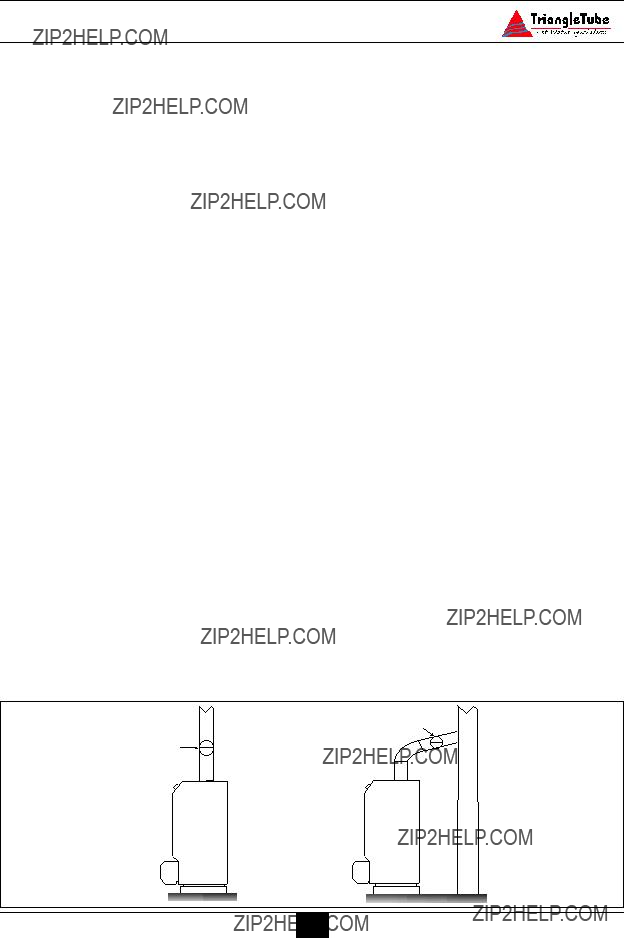
Removal of an Existing Boiler from a Common Vent System
BEST PRACTICES
For installations in which the ELITE is replacing an existing boiler / hot water heater system, which was connected to a common vent system with other appli- ances, the following steps shall be con- ducted with each remaining appliance connected to the common venting system:
1.Any unused openings in the common venting system must be sealed.
2.A visual inspection of the venting sys- tem must be conducted for proper siz- ing and horizontal pitch. The inspec- tion should ensure no blockage or restriction is within the vent system, and there is no leakage, corrosion or other items, which could cause an unsafe condition.
3.To adequately test the venting system, close all exterior doors and windows and all doors between the area contain- ing the remaining appliances connected to the common vent system and other areas of the building. Turn on any clothes dryers and any other gas appli-
ance not connected to the common vent system. Turn on all exhaust fans, i.e. range hoods and bathroom exhaust fans, preferably at maximum speed. Close any fireplace dampers.
4.Place in operation the first appliance being inspected that is connected to the common vent system. The remaining appliances should not be in operation. Follow the appliance???s lighting instruc- tions and adjust the thermostat to allow the appliance to operate continuously.
5.Test for spillage at the draft hood relief opening after 5 minutes of main burner operation. Spillage can be detected using the flame of a match or candle or with smoke from a cigarette.
6.Once it has been determined that each remaining appliance connected to the common vent system is properly vent- ed, return doors, windows, exhaust fans, fireplace dampers and any oper- ating gas appliance to their previous condition.
Should any improper operation of the common venting system be detected in the outlined test, the condition should be corrected so the vent system conforms with the National Fuel Gas Code, NFPA 54/ ANSI Z223.1 - latest edition. Canadian installations must conform with B149.1 or 149.2 Installation Code.

SECTION III - Unit Preparation
Handling Instructions
The ELITE is generally easier to handle and maneuver once removed from the shipping car- ton and pallet.
To remove the shipping carton and pallet:
a.Remove the shipping straps and open the top of the shipping carton to remove the wood shipment insert.
b.Lift the shipping carton over the unit to remove. If ceiling height is limited the carton maybe cut open using care not to damage the exterior jacket of the unit.
c.Discard all packing materials.
Hydrostatic Pressure Test
BEST PRACTICES
Prior to permanently connecting water, oil/gas supply or electrical supply, per- form a pressure hydrostatic test of the outer tank to ensure all piping connec- tions were not damaged during ship- ment.
Hydrostatic Test Preparation
1.Mount the circulator on the supply pipe as shown in Fig. 7 page 20.
2.Temporarily plug the primary return con- nections as shown in Fig. 7 page 20 using a 1??? NPT pipe plug. Use pipe dope sparing- ly to allow removal of the plugs upon com- pletion of the test.
3.On the outlet flange of the circulator pipe install a 1??? NPT nipple and shut-off valve. Use pipe dope sparingly to allow removal of the fittings upon completion of the test.
NOTICE
To avoid getting water onto the unit and/or surrounding area additional pip- ing from the shut-off to a catch bucket or drain may be required.
4.Connect a hose to the primary circuit drain valve located per Fig. 28 page 50, Item 2 and connect the other end to a fresh water supply. Ensure the hose can be used as a drain hose upon completion of the test.
Hydrostatic Test Procedures
1.Open the shut-off valve installed on the outlet flange of the circulator.
2.Open the fresh water supply valve and then open slowly the primary circuit drain valve to fill the outer tank with water.
3.When the water within the outer tank reaches the shut-off on the primary supply, close the primary circuit drain valve.
4.Close the shut-off valve, on the top of the circulator.
5.Slowly reopen the primary circuit drain valve until the test pressure on the temper- ature / pressure gauge reaches 10 psig maximum. Close the primary circuit drain valve.
CAUTION
To prevent damage to the inner tank the test pressure must not exceed 10 psig.
6.Allow the test pressure to remain for 10 minutes.
WARNING
Do not leave the unit unattended while pressurized. A cold water fill could expand and cause excessive pressure, resulting in severe personal injury, death or substantial property damage.
Unit Preparation
7.Ensure constant gauge pressure has been Completion of Hydrostatic Test and Draining maintained throughout the 10 minute test. 1. Disconnect the fill hose from the freshCheck for leaks at all fitting joints. Repair
if found.
WARNING
Leaks must be repaired immediately when detected. Failure to repair leaks can damage the unit, resulting in sub- stantial property damage.
8.Check continuity using a voltmeter across the terminals of the LWCO device. The contacts on the LWCO should be closed. See item 6 in Fig. 24 page 47 for location of the LWCO.
water source and direct the hose to a suit- able place of drainage.
2.Open the primary drain valve and complete- ly drain the unit. To aid in draining, open the shut-off valve on the primary supply.
3.Remove the hose from the primary drain valve when draining is complete.
4.Remove the plugs, nipple, shut-off valve and any other piping unless they will remain for use in the system piping.

SECTION IV - Domestic Piping
General Piping Requirements
???All plumbing must meet or exceed all local, state and national plumbing codes.
???Use pipe dope or tape suitable for potable water.
???Use isolation valves to isolate system components.
???Install unions for easy removal of the ELITE from the system piping.
Domestic Supply Pressure
For applications in which the domestic sup- ply pressure exceeds 70 psig it is recom- mended to install a pressure reducing valve on the cold water supply.
Maintaining the cold water supply at or below 70 psig will prevent normal thermal expansion from repeatedly forcing the T&P relief valve open.
Thermal Expansion
If the cold water supply contains a backflow preventer, check valve and / or a pressure reducing valve, the installer must install a domestic thermal expansion tank on the cold water supply. (See Fig. 2 page 14)
Installing a thermal expansion tank will prevent normal thermal expansion from repeatedly forcing the T&P relief valve open.
When installing a thermal expansion tank ensure the charge pressure of the tank is equal to the cold water supply pressure at the point of installation. Consult the ther- mal expansion tank manufacturer???s instruc- tions for further information on installation and sizing.
CAUTION
The Temperature / Pressure relief valve is not intended for constant duty, such as relief of pressure due to normal thermal expansion.
Water Hammer
Water hammer is the effect of sudden pres- sure changes occurring in the domestic pip- ing. These pressure changes are typically the result of ???fast acting??? positive shut-off valves closing. These types of valves can be typically found on dishwashers and clothes washers.
The effects of water hammering can cause damage to system components and tank welds on the unit.
Installation of hammer arresters is recom- mended at these types of appliances, which incorporate ???fast-acting??? positive shut-off valves. Consult the manufacturer of water hammer arresters for recommendation on sizing and installation requirements.
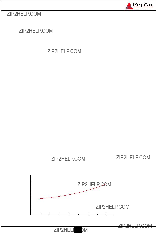
Temperature / Pressure Relief Valve
The ELITE has a factory installed Temperature / Pressure Relief valve. Ensure the rating of the T&P relief valve is correctly sized as follows per AGA:
The installer must install discharge piping onto the T&P relief valve. The discharge piping must be:
???Made of material serviceable for tem- peratures of 250??F or greater.
???Directed so that any hot water dis- charge flows away from all persons.
???Directed to a suitable place of drainage.
???Installed as to allow complete draining of the T&P relief valve and the dis- charge piping.
???Terminated with a plain end, not with threads.
WARNING
DO NOT install any valves between the T&P relief valve and the discharge pip- ing. DO NOT plug the T&P relief valve or the discharge piping. Improper place- ment and piping of the T&P relief valve can cause severe personal injury, death or substantial property damage.
Thermostatic Mixing Valve
The ELITE contains a factory installed thermo- static mixing valve with built-in check valve.
The operating range of the thermostatic mixing is 90??F to 120??F.
CAUTION
Failure to properly direct the discharge piping of the T&P relief valve may result in flooding of the area adjacent to the unit and or lower floors in the structure causing substantial property damage.
The installer must not install the T&P relief valve discharge piping in a manner that is:
???Excessively long: Using more than 2 elbows and/or 15 feet of discharge pip- ing can reduce the discharge capacity.
???Terminated directly into a drain: The discharge piping must terminate within 6 inches of the drain. Check with local plumbing codes for termination guide- lines.
???The discharge piping is plugged, reduced in size or restricted in any manner.
???The discharge piping is subject to freez- ing.
For applications with a domestic recirculation loop, the recirculation pump should be con- trolled by an aquastat. The maximum recom- mended setting of the aquastat is 10??F lower than the thermostatic mixing valve setting.
DANGER
For proper operation of the thermostatic mixing valve and to prevent potential scalding hazards, the recirculation loop should be controlled by an aquastat. DO NOT use continuous recirculation.
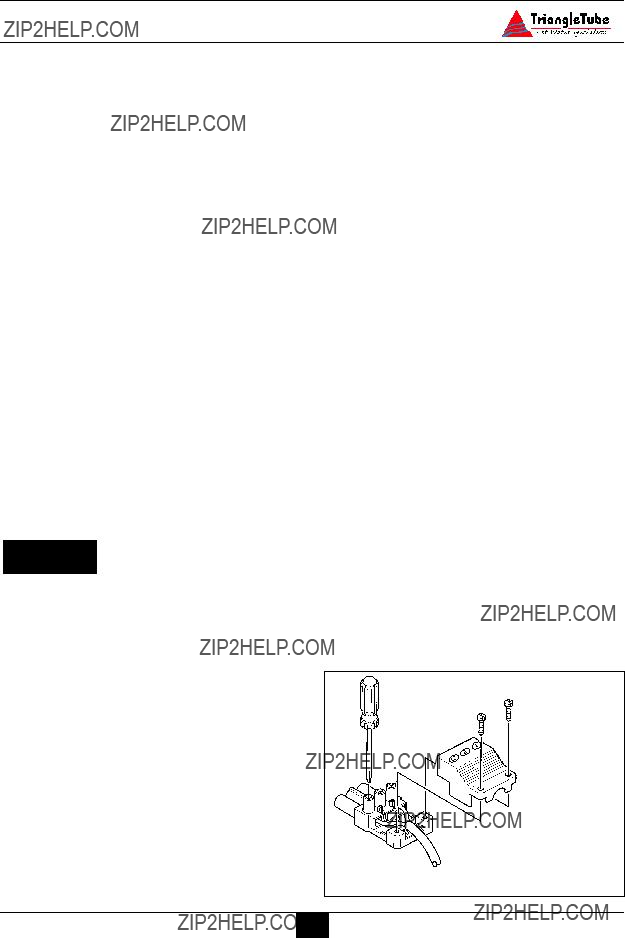
U-Tube Assembly
The ELITE is supplied with a U-Tube Assembly that directs cold water to the thermostatic mixing valve.
To install the U-Tube Assembly the installer must:
1.Disconnect the cold inlet adapter/union from the thermostatic mixing valve.
2.Using needle-nose pliers remove the plastic check valve assembly from the adapter.
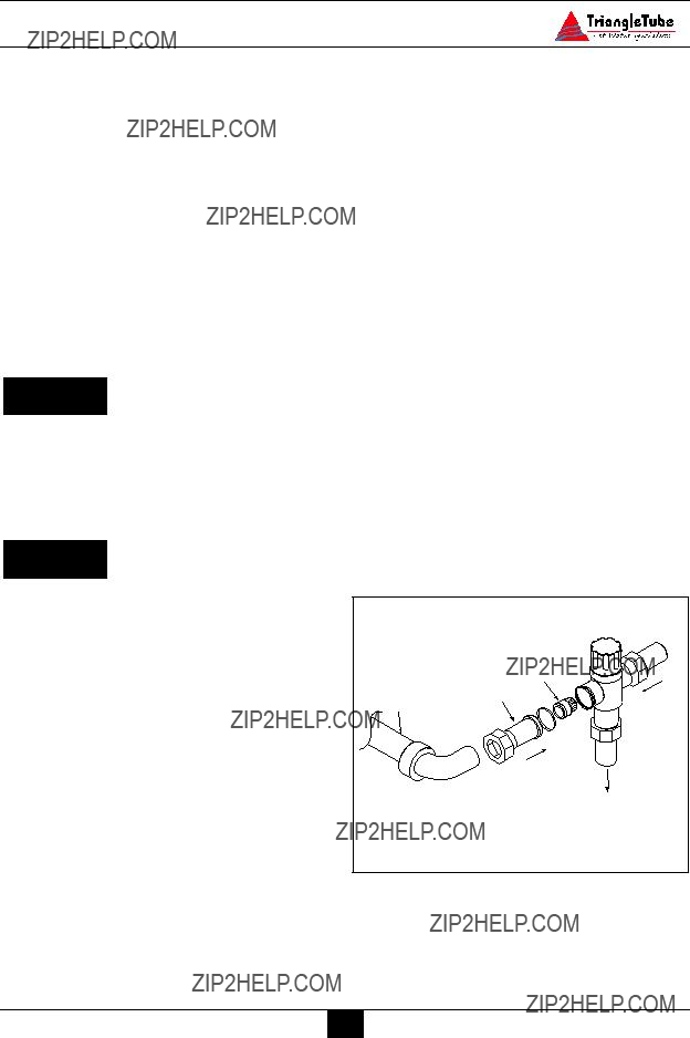
3.Solder the U-Tube Assembly onto the adapter. (See Fig. 1)
4.Once the adapter has sufficiently cooled, re-insert the check valve assem- bly making sure of orientation and reconnect onto the mixing valve.
If the installation of the ELITE requires domestic hot water for a commercial dish- washer, the installer may insert a tee con- nection between the unit and the mixing valve to provide 140??F domestic hot water. The installer must reference local plumbing codes to ensure if this type of application is permissible.
DANGER
The thermostatic mixing valve MUST be installed and utilized on the ELITE. Removal of the thermostatic mixing valve will result in severe personal injury or death.
CAUTION
The installer should remove the thermostatic mixing valve from the units and install a single thermostatic mixing valve at the outlet of the hot water manifold. The thermostatic mixing valve should be sized according to the required flow rate and pressure drop. Refer to the ther- mostat mixing valve manufacturer specifica- tion and installation instructions for more details.
Reference Fig. 4, page 15 for piping diagram.
Storage Tank Application
For applications requiring large volumes of domestic hot water in a relative short period, the installer may include a storage type tank (see Fig. 5 page 16) in the domestic piping. The installer must:
1.Relocate the thermostatic mixing valve from the ELITE to the outlet of the stor- age tank.
2.Provide recirculation from the storage tank back to the ELITE using a bronze type circulator. Maximum recommend- ed flow rate is 5 to 10 gpm.
The manual valve on the U-Tube assem- bly must remain in the full open position for proper operation of the thermostatic mixing valve.
Domestic Drain Valve
-The installer must install a drain valve and drain leg as shown in Fig. 2 page 14 or Fig. 3 page 15.
-The drain valve should be positioned close to the floor to aid in the siphon action required to drain the inner tank.
Multiple Units Installation
For applications using multiple units the domestic piping should be piped using a bal- anced manifold arrangement.
TR/SMART Series Application
For applications requiring large volumes of domestic hot water over an extended period, the installer may include a Triangle Tube TR/SMART Indirect Water Heater in conjunc- tion with the ELITE. (See Fig. 6 page 16)
The domestic system recirculation, if used, is directed to the TR/SMART Series Tank. The circulator should be controlled by an aquastat.
The primary piping to the TR/SMART Series tank must comply with the piping methods details in SECTION V - Primary Piping or with other recognized piping methods.
Additional information regarding domestic and primary piping can be found in the TR/SMART Installation Manual.
Domestic Piping Diagrams
U-Tube???
??? assembly 3*
To dishwasher if??? permitted by codes

 1
1
12" Heat trap
???

 Cold water 3 inlet
Fig. 2: ELITE Without Recirculation
* Optional devices may be required by local Codes
14
Domestic Piping
Optional recirculation line
 3
3

 Cold water 3 inlet
* Optional devices may be required by local Codes
15
Domestic Piping
Domestic Piping

 1
1
To dishwasher if??? permitted by codes
12" Heat trap
6
 3
3
 8 7 2
8 7 2

 Cold water 3 inlet
Fig. 5 : ELITE with Storage Tank
3

 1
1
To dishwasher if permitted by codes

 Cold water 3 inlet
6
8
Fig. 6: ELITE with TR/SMART Indirect Water Heater
* Optional devices may be required by local Codes
16

SECTION V - Primary Piping
General Piping Requirements
Low Water Cutoff Device
-The ELITE is equipped with a factory installed pressure switch style Low Water Cut Off device.
-The minimum operating system pressure allowable with this device is 10 psig.
-Check local codes which require a low water cutoff device for compliance of this device.
Backflow Preventer
-Use a backflow preventer valve in the make-up water supply to the unit as required by local codes.
Primary System Piping Applications
BEST PRACTICE
All piping applications shown in this instal- lation manual utilize a primary/ secondary piping arrangement. This method is rec- ommended as a means to provide priority to the production of domestic hot water. For other piping arrangements, consult the Engineering Department at Triangle Tube or consult other approved/recognized design arrangements.
BEST PRACTICE
On piping applications utilizing a single zone or other recognized piping design arrangements it is recommended the installer uses flow/check valves with weighted seats at or near the appliance to prevent gravity circulation.
Expansion Tank and Makeup Water
Ensure the expansion tank is properly sized for the outer tank volume (22 gallons) and the system volume and temperature.
CAUTION
Undersized expansion tanks will cause sys- tem water to be lost through the pressure relief valve and cause additional makeup water to be added to the system. Eventual primary tank failure can result due to this excessive makeup water addition.
The expansion tank must be located as shown in Fig. 7, 7A or 7B page 20 or as per recognized design methods. Refer to the expansion tank manufacturer instructions for additional installation details.
Connect the expansion tank to an air sepa- rator only if the air separator is located on the suction side (inlet) of the system circu- lator. Always locate and install the system fill connection at the same location as the expansion tank connection to the system.
Diaphragm (Bladder) Expansion Tank
Always install an automatic air vent on the top of the air separator to remove residual air from the system.
Closed-Type (Standard) Expansion Tank
It is recommended to pitch any horizontal piping toward the expansion tank 1 inch per 5 feet of piping. Use 3/4??? piping for the expansion tank to allow air within the sys- tem to rise.
For proper operation of the expansion tank and system, remove the factory installed automatic air vent from the ELITE and plug the connection. (See Item 10, Fig. 28 page 50)

CAUTION
DO NOT install automatic air vents on a closed-type expansion tank system. Air must remain in the system and be returned to the expansion tank to pro- vide an air cushion. An automatic air vent would cause air to be vented from the system resulting in a water-logged expansion tank.
Circulator
The ELITE is supplied with a circulator that is pre-wired to allow for domestic priority. Locate the circulator in the return or supply piping as shown in the piping diagrams included in this manual.
Closet (Zero Clearance) Applications
For applications in closets or zero clear- ances, the installer may use the upper prima- ry connection shown as Item 4 Fig. 28 on page 50 as a primary return connection. The air elimination, expansion tank and make-up water system should then be piped directly into the primary loop of the space heating prior to the system circulator.
Sizing Primary Piping
See Fig. 8 through 11, pages 21 - 22, for recommended piping arrangements based on various applications. In all diagrams, the space heating system is isolated from the ELITE using primary / secondary pip- ing connections.
Size the piping and system components required in the space heating system using recognized design methods.
System Piping - Zone Circulators
Connect the ELITE to the system piping as shown in Fig. 9 page 21 when zoning with zone circulators. The circulator supplied with the ELITE should not be used for a heat zone. It must supply only the prima- ry loop.
Install a separate circulator for each zone of space heating.
To control the zone circulators refer to Fig. 19, page 35.
NOTICE
To ensure adequate flow rate through the ELITE, maintain a minimum 1 inch diameter on the system piping connect- ing the unit to and from the primary / secondary connection.
System Piping - Zone Valves
Connect the ELITE to the system piping as shown in Fig. 9 page 21 when zoning with zone valves. The primary / secondary pip- ing ensures the priority is given to the pro- duction of domestic hot water.
To control the system zone valve refer to Fig. 18, page 34.
NOTICE
To ensure adequate flow rate through the ELITE, maintain a minimum 1 inch diameter on the system piping connect- ing the unit to and from the primary / secondary connection.
System Piping - Radiant Heating with Mixing Valve
Connect the ELITE to the system piping as shown with a radiant system using a thermo- static mixing valve as shown in Fig. 11 page 22. The primary / secondary piping ensures sufficient return temperature to the ELITE.

If the radiant system tubing contains no oxygen barrier, a stainless steel heat exchanger must be used. Failure to install a heat exchanger could lead to premature failure of the outer tank and void any warranty claim.
WARNING
Radiant heating system piping should include a means of regulating the boiler return water. The return water tempera- ture to the unit should be maintained at 130??F or higher. Failure to prevent low return water temperature to the unit could cause premature failure of the unit and it???s burner system resulting in severe personal injury, death or substantial property damage.
Size the system piping and circulator to pro- vide the flow needed for the radiant system.
To control the zone circulators refer to Fig. 19, page 35.
To ensure adequate flow rate through the ELITE, maintain a minimum 1 inch diameter on the system piping connect- ing the unit to and from the primary / secondary connection.
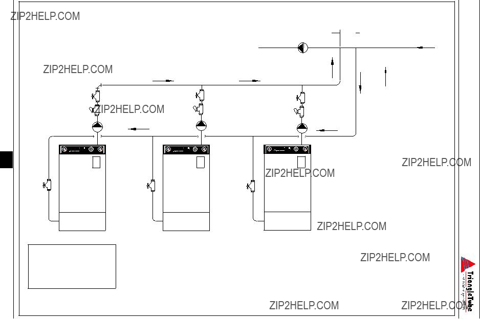
System Piping - Multiple Units Installation
Use a balance manifold system as the pri- mary / secondary connection to the space heating piping as shown in Fig. 12 page 23.
Refer to Fig. 7 page 20 to install air elimi- nation and expansion tank.
For the space heating piping refer to the applications mentioned in this manual or use recognized design methods.
NOTICE
To ensure adequate flow rate through the ELITE, maintain a minimum 1 inch diameter on the system piping connect- ing the unit to and from the primary / secondary connection.
Primary Piping
Near Appliance Piping

 2
2
Return
flow
Fig. 7 : Near Appliance Primary
Piping with a Diaphragm
Type Expansion Tank
Fig. 7A :
Return
flow
 1
1
Near Appliance Primary Piping with Closed - Type Expansion Tank
Fig. 7B : Near Appliance Primary Piping
with Diaphragm - Type Expansion
Tank (Alternate Circulator Location)
???Size primary manifold for total flow of all circulators
???Size each circulator to indi- vidual circuit requirements
???Install balancing valves to adjust flow to distribute heat to all zones
Fig. 8: Primary piping - Zoning with Circulators
 5
5
Fig. 9: Primary Piping - Zoning with Zone Valves
2
6
M
 5
5
 5
5
2 
Note: Adjust system temperature valve to establish maximum sup- ply/return temperature differen- tial of 30??F and a minimum 130??F return water temperature to the ELITE
Fig. 10: Primary Piping - Low Temperature Radiant System
2
6
2 
12" Max.
2
Air Handler Load
Fig. 11: Primary Piping - Multi Temperature System
4
To the System 
1.Unit Circulator
2.Shut Off Valves
3.Flow Check Valve
4.System Circulator
Fig. 12: Primary Piping - Multi Units Installation
Recommended placement of expansion tank and make up water supply.

SECTION VI - Venting
Oil Vent - General Requirements
WARNING
Improper installation of vent system could cause improper draft causing flue gas leakage and carbon monoxide emis- sions, which could cause severe personal injury or death.
Installation must comply with local require- ments for oil burning appliances. In absence of local codes the installer should refer to:
???NFPA 31, Installation of Oil-Burning Equipment
???NFPA 211, Standard for Chimneys, Fireplaces, Vents and Solid Fuel Burning Appliances.
???In Canada, the installer should refer to CSA B139, Installation Code for Oil- Burning Equipment.
NFPA 211 requires the chimney to be lined before connecting to the ELITE appliance.
DANGER
Inspect existing chimney before installing the ELITE. Failure to com- plete the following guidelines will result in severe personal injury or death:
-Clean the chimney, including removal of any blockages
-Repair or replace any deteriorating or damaged vent pipe or liner
The chimney must extend a minimum 3 feet above the highest point where it passes through the roof and 2 feet higher than any portion of the building within 10 feet.
The cross sectional area of the chimney and the height must be increased at minimum 4% per 1,000 feet of elevation above sea level.
The installer must maintain minimal clearances from the vent pipe to combustible material as follows:
-Type ???L??? doublewall vent - 6 inches
-Single wall vent pipe - 18 inches
The chimney size should be maintained as min- imal, oversize chimneys could result in the for- mation of condensate in the chimney.
Oil Vent Piping
WARNING
Long horizontal vent runs, excessive number of tees or elbows or other fittings that restrict the combustion flue gas flow can result in potential flue condensation, flue gas leakage and/or carbon monoxide emissions, which can lead to severe per- sonal injury or death.
When the burner and the ELITE are properly installed, the overfire draft on the ELITE should be approximately (-)0.01???w.c to (-)0.02???w.c.
- Repair any damaged chimney mor- tar or joints
Minimum Chimney Size - Oil Fired
24
Install an induced draft fan in the chimney for applications in which:
-Excessive resistance to the flow of flue gases is excepted
-The cross-sectional area of the chimney is smaller than the minimal area required
-The chimney height is less than the minimal requirement
When using an induced draft fan the installer should seal all vent joints and provide an inter- lock system for the ELITE to ensure fan oper- ation.
Oil Vent - Direct Vent Applications
The installer must read and comply with the direct vent instruction outline in Triangle Tube Oil-Fired Direct Vent Instructions.
The installer should give attention to the loca- tion of the ELITE prior to installation. The installer should:
-Locate the unit for shortest possible vent length and the most direct path to the outside wall.
-Note that flue gases will form a white plume in colder climates which may obstruct window views
The installer should consider the following when determining the location of the vent ter- mination:
-Locate or guard the vent termination in a manner to prevent accidental contact by people or pets.
-Vent must terminate at least 4 feet below and 4 feet horizontally or 1 foot above any window, door or gravity air inlet to the building.
-Vent must terminate not less than 7 feet above grade when located adjacent to a public sidewalk.
-Terminate the vent at least 6 feet from adjacent walls
-The bottom of the vent termination shall be located at least 1 foot above the grade, including normal snowline.
-DO NOT terminate the vent into win- dow wells, stairwells, alcoves, court- yards or other recess area.
-DO NOT terminate vent above any window, door or gravity inlet as con- densate can freeze causing ice forma- tions.
Gas Venting -General Requirements
The venting system must be installed in accor- dance with:
-NFPA54 National Fuel Gas Code, ANSI Z223.1.
-NFPA 211 Standard for Chimneys, Vent and Solid Fuel Burning Appliances.
For installations in Canada the venting system must be installed in accordance with:
-CGA / B149 Installation Code for Gas Burning Equipment.
-Prior to installing the appliance into an existing chimney or venting system, the vent system should be inspected for condition and obstructions.
WARNING
If the inspection reveals the vent system is not safe for the intended use, it shall be repaired, rebuilt, lined, relined or replaced with a vent or chimney to con- form to NFPA 211, latest edition. Failure to conduct such an inspection and/or repair could result in severe personal injury, death or substantial property damage.
-No portion of the venting system shall extend into or pass through any circu- lating air duct or furnace plenum.
-The gas venting system shall be installed, supported and spaced in accordance with their listings and the manufacturer???s instructions.
Masonry and Metal Chimneys
-The NFPA code book severely limits the installation of the ELITE into a masonry chimney. For applications using either interior or exterior masonry chimney a listed, approved metal chimney lining system should be used.
BEST PRACTICE
For any applications using an exterior chimney it is recommended that an insu- lated or stainless steel chimney lining system be used.
NOTICE
A chimney with one or more sides exposed to the outside of the structure is considered to be an exterior chimney.
-The chimney shall extend at least 5 feet above the highest connected appliance flue collar.
-The chimney shall extend at least 3 feet above the highest point where it passes through a roof of a building and at least 2 feet higher than any portion of a building within a horizontal distance of 10 feet.
Type B Vent Systems
-The vent system should terminate in accordance with NFPA 54, latest edi- tion, provided the termination is at least 8 feet from a vertical wall or similar obstruction.
BEST PRACTICE
The Type B vent system shall extend in a general vertical direction with offsets not exceeding 45 degrees. A vent system having not more than one 60 degree off- set shall be permitted. Any angle greater than 45 degrees is considered horizontal.
BEST PRACTICE
The total horizontal distance of a vent plus the horizontal vent connector shall not be greater than 75% of the vertical height of the vent.

Vent Connectors
-When a vent connector must be located in or pass through an un-conditioned space, attic or crawl space, that portion of the vent connector must be listed as Type B or other approved material hav- ing equivalent insulation qualities.
-The minimum clearance to com- bustibles for single wall vent connec- tors shall be 6 inches.
-The minimum clearance to com- bustibles for Type B vent connectors shall be 1 inch or per vent manufactur- er???s instructions.
-The vent connector shall be installed in a manner to avoid excessive turns or other construction features that create excessive resistance to the flow of the vent gases.
-The vent connector should be installed in a manner without any dips or sags and should slope upward toward the vent or chimney at least 1/4 inch per 1 foot.
-The location of the appliance should be located as close to the vent or chimney to maintain the vent connector length as short as possible.
BEST PRACTICE
-The entire length of a vent connector shall be readily accessible for inspec- tion, cleaning and replacement.
-The diameter of the vent connector should not be upsized more than two sizes greater than the flue outlet diameter.
WARNING
The vent system must be designed and installed in compliance with all applica- ble codes. Failure to properly size and install the vent system could result in severe personal injury, death or substan- tial property damage.
Common Vent Systems
The ELITE may be vented into a common vent system using the guidelines and sizing Tables of the National Fuel Gas Code NFPA 54 ANSI Z223.1 latest edition.
The ELITE may also be vented into a common multi story vent using the guidelines and sizing Tables of the National Fuel Gas Code NFPA 54 ANSI Z223.1 latest edition.
The maximum horizontal length allow- able should not exceed 75% of the height of the vent or chimney assuming no off- sets in the vertical vent.
Gas Fired Installations
27

SECTION VII - Fuel Piping
Gas Supply Piping Connection
NOTICE
The gas supply piping must be installed in accordance to all applicable local, state and national codes and utility requirements.
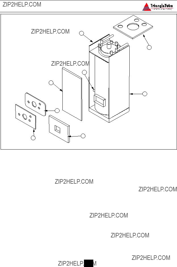
1.Remove the burner jacket hood. Refer to Fig. 15 to pipe gas supply to the burner.
a.Install a pipe union at the factory sup- plied gas nipple, for ease of service.
b.Install a manual shutoff valve in the gas supply piping as shown in Fig. 15. For installations in Canada the installer must tag and identify the main shutoff valve.
c.Install a drip leg on the gas supply line prior to connecting to the ELITE gas train as shown in Fig. 15.
2.Support the gas piping using hangers. Do not support the piping by the unit or its components.
3.Purge all air from the gas supply piping.
4.Before placing the ELITE into operation, check and test all connections for leaks.
Close the manual shutoff valve during any pressure test with less than 13???w.c..
Disconnect the ELITE and its gas valve from the gas supply piping during any pressure test greater than 13???w.c..
WARNING
Do not check for gas leaks with an open flame. Use a gas detection device or bub- ble test. Failure to check for gas leaks can cause severe personal injury, death or substantial property damage.
5.Use pipe dope compatible with natural and propane gases. Apply sparingly only to the male threads of pipe joints so that pipe dope does not block gas flow.
WARNING
Failure to apply pipe dope as detailed above can result in severe personal injury, death or substantial property damage.
WARNING
Use a two-wrench method of tightening gas piping near the unit and its gas valve. Use one wrench to prevent the gas valve line connection from turning and the sec- ond to tighten adjacent piping. Failure to support the gas valve connection pip- ing could damage the valve and the gas line components.
Fig. 15: Recommended Gas Supply Piping
Pipe Sizing - Natural Gas
1.Refer to Table 1 for pipe length and diame- ter requirements. Based on rated ELITE input (divide by 1,000 to obtain cubic feet per hour).
Pipe Sizing - Propane Gas
1.Contact the local propane gas supplier for recommended sizing of piping, tanks and 100% lockup gas regulator.
-Table 1 is based on Natural Gas with a Propane Gas Supply Pressure Requirements specific gravity of 0.60 and a pressure 1. Adjust the propane supply regulator pro-
- For additional gas piping sizing infor- mation, refer to ANSI Z223.1. For Canadian installations refer to B149.1 or B149.2.
2.Pressure required at the gas valve inlet sup- ply pressure port:
-Maximum 13???w.c. at flow or no flow conditions to the burner
Table 1: Gas piping sizing - Natural Gas

General Oil Piping Guidelines
Location and installation of oil tanks, oil piping and burners must comply with:
-NFPA 31, Standard for the Installation of Oil-Burning Equipment
-Local codes and regulations
-Manufacturer???s information provided with the burner and oil pump.
For installations in Canada, CSA B139, Installation of Oil-Burning Equipment
If the fuel tank is installed or any part of the fuel tank is above the level of the burner, an anti-siphon device must be installed to prevent
the spillage of oil in the event of an oil line break.
Support oil line as required by local codes.
All tank connections should be made using swing joints or copper tubing to prevent possi- ble line breakage in the event of tank settle- ment. When using swing joints ensure they are made to tighten as the tank settles. All thread connections should be made with a non-hard- ening pipe joint compound.
WARNING
Do not use Teflon tape to seal any oil con- nections. Teflon tape can cause oil valves to fail, creating potential hazards. Do not use compression type fittings at the burner all fittings should be flare type.
SECTION VIII - Internal Wiring
WARNING
ELECTRICAL SHOCK HAZARD. For your safety, disconnect electrical power supply to the unit before servicing or making any electrical connections to avoid possible electric shock hazard. Failure to do so can cause severe person- al injury or death.
NOTICE
General Requirements
-Wiring must be N.E.C Class 1.
-If original wiring as supplied with the unit must be replaced, use only type 90??C wire or equivalent.
-The ELITE must be electrically grounded as required by National Electrical Code ANSI/NFPA 70 - latest edition.
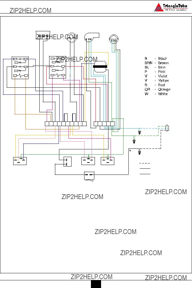
All electrical contacts shown in Figures 15 & 16 pages 31 & 32 do not have elec- trical power applied. Shown as ???off- shelf??? condition.
Fig. 16: Factory Wiring Schematic
32
SECTION IX - External Wiring
Installation Compliance
All field wiring made during installation must comply with:
-National Electrical Code NFPA 70 and any other national, state, provincial or local codes or requirements.
-In Canada, CSA C22.1 Canadian Electrical Code Part 1, and any other local codes.
Line Voltage Connections
1.Connect 120 VAC power wire to the line voltage leads located behind the front con- trol panel.
2.Route the incoming 120 VAC power wire through the right side jacket panel.
3.Use the wire nuts provided to ensure a tight and secure connection.
4.The unit is provided with a service switch, check local code requirements for compli- ance.
NOTICE
If local electrical codes or conditions require an additional service switch, the installer must provide and install a fused disconnect or 15 amp (minimum) service switch.
Thermostat Wiring
1.Connect room thermostat or the end switch (isolated contact only) of a relay control panel to the Room Thermostat Snap-set located on the rear jacket panel.
2.Remove the snap-set cover and connect the thermostat wiring to terminals C and 1 per Fig. 17.
3.For proper operation install the room ther- mostat on an inside wall away from influ-
ences of heat and cold, i.e. water pipes, areas of draft, lighting fixtures and fire- places.
4.Set the thermostat anticipator (if applica- ble) as follows:
-Set for 0.2 amps when wired directly to the Room Thermostat Snap-set.
-Set to match the total electrical power requirements of the connected devices when wired to zone relays or other devices. Refer to the relay manufactur- ers??? specifications and the thermostat instructions for additional information on the anticipator setting.
Outdoor Temperature Limit
1.The ELITE may operate with a variable primary operating temperature using an outdoor reset control provided by the installer.
2.Remove the factory jumper across termi- nals 9 and 10 of the wiring terminal. Connect the outdoor limit control to those terminals.
3.Set the operating limits of the outdoor limit control as follows:
-Maximum operating temperature of 180??F.
-Minimum operating temperature of 150??F.
Fig. 17: Room Thermostat Snap-set Wiring
External Wiring
C 1
To ELITE
"Room Thermostat"
Snap Set
Zone 1
Room
Thermostat
Zone 2
Zone
Valve
*Use isolation relay on 3-wire zone valve with non-isolated end switch. Transformer and the ELITE control can burn out if isolation relay is not used.
* Isolation relay
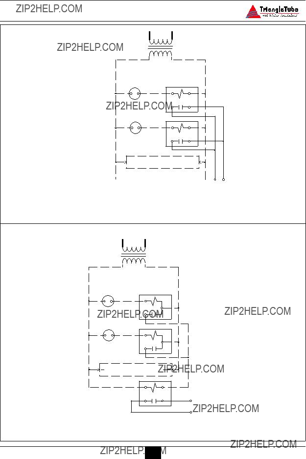
Fig. 18: Multiple Zone Field Wiring Using Zone Valves
34
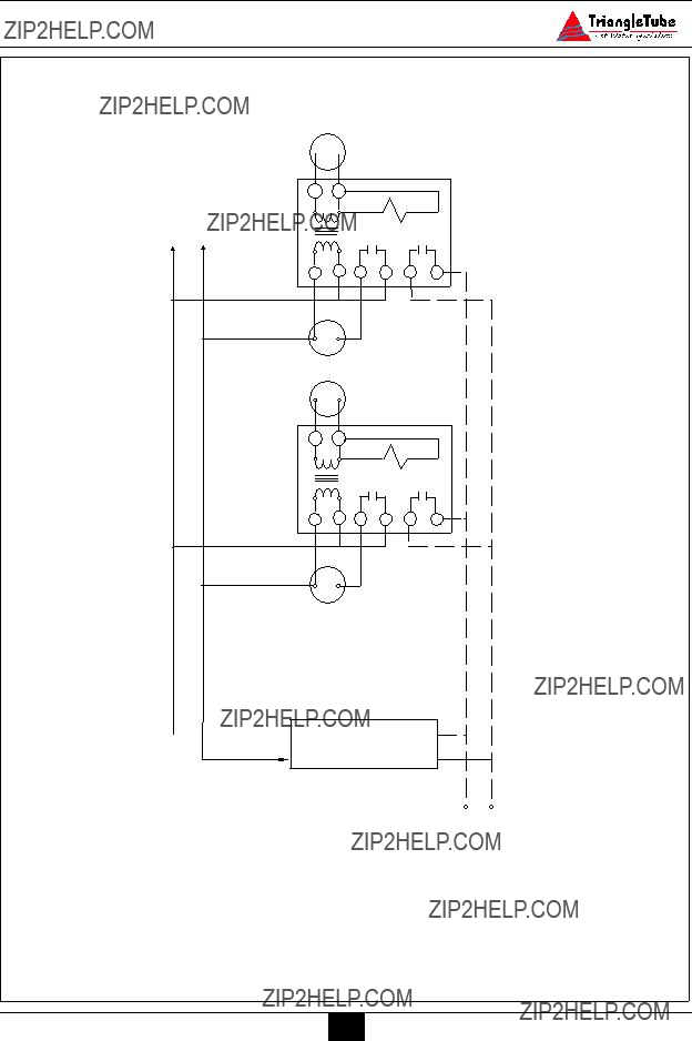
Honeywell 
 Thermostat
R845A zone 1
2 1 4 3 5 6
Circulator
Zone 1
Thermostat
zone 2
T T
2 1 4 3 5 6
Circulator
Zone 2
 Additional zones may be added as shown above
C 1
To ELITE
" Room Thermostat"
Snap Set
Fig. 19: Field wiring with zone circulators.
External Wiring
Fig. 20: Typical Zone Relay Panel Wiring
Bronze
Circulator
Fig. 21: Storage Tank Recirculation Wiring
36

4. Set the primary thermostat to the highest possible setting.
SECTION X - Start Up Preparation
Check System and Domestic Water
Chemistry
WARNING
Do not use petroleum-base cleaning or sealing compounds in the primary sys- tem. Damage to seals and gaskets in the system components could occur, result- ing in substantial property damage.
NOTICE
System water including additives must be practically non-toxic, having a toxicity rating or Class of 1, as listed in Clinical Toxicology of Commercial Products.
Water pH Level 6.0 to 8.0
Maintain the primary system water pH between 6.0 and 8.0. Check using litmus paper or contact a water treatment compa- ny for a chemical analysis.
If the pH does not meet this requirement, do not operate the ELITE or leave the unit filled until the condition is corrected.
Water Hardness Less Than 7 Grains
For areas with unusually hard water (hard- ness above 7 grains) consult a water treat- ment company.
Chloride Concentration Less Than 80 mg/L
For those installations that use a water soft- ener or conditioner, consult the water treat- ment company.
NOTICE
Any water conditioning system must be installed and maintained in accor- dance with the water conditioner???s manufacturer???s specifications and within the operating guidelines of the
ELITE.
Chlorinated Water
Do not use the ELITE inner or outer tank to heat a swimming pool or spa directly.
Maintain the chlorine level of the water in the inner and outer tanks at levels consid- ered safe for drinking.
Flush Primary and Domestic System to Remove Sediment
The installer must flush both the primary and domestic system to remove any sedi- ment to allow proper operation of the
ELITE.
Flush the systems until the water runs clean and is free of sediment.
For primary zoned systems, each zone should be flushed through a purge valve. Purge valves and isolation valves should be installed on each zone to allow for proper flushing of the system.
Check and Test Antifreeze
For primary systems containing antifreeze solutions, follow the antifreeze manufac- turer???s instructions in verifying the inhibitor level and to ensure the fluid char- acteristics are within specification require- ments.
Due to the degradation of inhibitors over time, antifreeze fluids must be periodically replaced. Refer to the manufacturer of the antifreeze for additional instructions.

NOTICE
System water including additives must be practically non-toxic, having a toxicity rating or Class of 1, as listed in Clinical Toxicology of Commercial Products.
Use of Antifreeze in the Primary System
WARNING
NEVER use automotive or ethylene gly- col antifreeze or undiluted antifreeze in the primary system as freeze protection. This can cause severe personal injury, death or substantial property damage if ignored.
Determine the antifreeze fluid quantity using the system water content volume and following the antifreeze manufacturer instructions.
The primary outer tank volume of the ELITE is 20 gallons. Remember to include the volume of the expansion tank.
Check with local codes requirements for the installation of back flow preventers or actual disconnect from the make up water supply line.
Ensure the concentration of antifreeze to water does not exceed a 50/50 ratio.
NOTICE
System water including additives must be practically non-toxic, having a toxicity rating or Class of 1, as listed in Clinical Toxicology of Commercial Products.
Filling the Inner (Domestic) Tank and
System
WARNING
Proceed with filling instructions for the inner and outer tanks only after ensur- ing the water meets the requirements listed in this installation manual. Failure to comply could result in damage and improper operation of the unit.
CAUTION
Never operate the ELITE unless both the inner and outer tanks are completely filled.
CAUTION
Always fill the inner tank prior to filling and pressurizing the outer tank. Failure to properly fill the inner tank could result in damage to the inner tank.
1.Ensure the domestic drain valve is closed.
2.Open the isolation valves on the domestic cold supply piping to the ELITE and on the domestic hot outlet piping to the building.
3.Vent any air from the domestic piping sys- tem by opening faucets near the unit. Continue filling the domestic system until there is a constant flow of water from the faucets.
4.Close the hot water faucets.
Filling the Outer (Primary) Tank and
System
1.Close the primary drain valve located on the rear of the unit and any manual or automatic air vent in the system.
2.Open all system isolation valves.

3.Fill the outer tank to correct system pressure. Correct pressure will vary with each application.
NOTICE
Typical residential system fill pressure is 12 psi. System pressure will increase when system temperature increases. Operating pressure of the system should never exceed 25 psi.
4.Allow air to escape from the outer tank by opening the automatic air vent provided with the ELITE.
5.Purge air in each zone of the primary sys- tem through the purge valve. Open air vents to allow air to be purged in the zones.
6.Once the system is completely filled and purged of all air, check the system pressure and check for leaks.
Check Low Water Cut-Off Device
-The ELITE is provided with a factory installed Low Water Cut-Off device that measures system pressure of more than 10 psi.
-Remove the front jacket panel and check for continuity across the low water cut-off device wire terminals. The contacts should be closed when sys- tem pressure is greater than 10 psi.
Check For Gas Leaks (if applicable)
WARNING
Prior to start-up and during initial oper- ation, smell near the floor and around the unit for gas odorant or any unusual odor. Do not proceed with the start-up if there is any indication of a gas leak. Any leaks found must be repaired immediately.
WARNING
Propane installations only - The propane supplier mixes an odorant with the propane to make its presence detectable. In some cases the odorant can fade and the gas may no longer have an odor.
Prior to start-up of the unit and period- ically after start-up have the propane supplier check and verify the odorant level.
Check Thermostat Circuit
-Unplug the Room Thermostat Snap-set located on the rear of the unit.
-Connect a voltmeter across the end ter- minals of the male half of the Room Thermostat Snap-set.
-Close each thermostat, zone valve and relay in the external circuit one zone at a time and check the voltage reading across the plug.
-There should NEVER be voltage mea- sured at the plug.
-If voltage is measured at the plug under any condition, check and correct the external wiring.
NOTICE
In systems using 3-wire zone valves backfeed of voltage to the unit is a com- mon problem. Use an isolation relay to prevent voltage from the external circuit entering the Room Thermostat Snap- set.

SECTION XI - Start-Up Procedures
Final Checks Before Start-up
Verify the ELITE and the primary and domestic systems are full of water and all system components are correctly set for operation.
Verify Start-up Preparation items outlined on pages 37 thru 39 have been completed.
Verify all electrical connections are correct and securely fasten.
Inspect vent piping and combustion air inlet piping for signs of deterioration from corrosion, physical damage or sagging. Verify combustion air piping and vent pip- ing are intact and correctly installed.
Adjustment of the Secondary Thermostat
Limit.
The Secondary (Domestic) Thermostat located on left side of the control panel maintains the minimum domestic water storage temperature.
Set the thermostat knob as shown in Fig. 22 page 42.
Maximum limit setting is 140??F
ELITE Start-up
Turn the ON-OFF switch located on the front control panel to the OFF position. Turn the electrical supply or any service switch to the unit in the ON position.
Check Domestic Piping.
Check domestic piping and system components for leaks. If found, shut down the unit and repair immediately.
Check Primary Piping.
Check primary system piping and com- ponents for leaks. If found, shut down the unit and repair immediately.
Purge any remaining air from the system piping. Air in the system piping will
interfere with circulation creating heat distribution problems and system noise.
Check Vent Piping
Check for gas-tight seal at every connec- tion and seam of the venting.
WARNING
Venting system must be sealed gas-tight to prevent flue gas spillage and potential carbon monoxide emissions, which will result in severe personal injury or death.
Check Gas Piping (if applicable)
1.Check around the unit for gas odor fol- lowing the procedure outlined in this manual on Page 39.
WARNING
If any gas leaks are found or suspected, shut the unit down immediately. Use a gas detection device or bubble test to locate the source of the gas leak and repair at once. Do not operate the unit until the leak is corrected. Failure to comply with this procedure could result in severe personal injury, death or sub- stantial property damage.
Check Oil piping (if applicable)
Check for any leakage at the pump and all fittings
Verify Flame Pattern and Combustion
Check the flame pattern through the inspection port of the burner. The flame should be stable.
Test for CO2 or O2 and for CO. The combustion reading should be within the range listed in Table 2 page 41. The CO level should not exceed 100 ppm when combustion is correct.
WARNING
A combustion test must be performed after any burner adjustments are made. Allow the unit to operate for approxi- mately 10 minutes after adjustment before measuring any combustion levels. Failure to comply with these procedures could result in severe personal injury, death or substantial property damage.
Check overfire draft
The overfire draft should measure typi- cally (-) 0.01??? w.c to(-) 0.02??? w.c in the combustion chamber. Refer to Triangle Tube???s Burner Specification for actual measurements.
Measure Input - Natural Gas Only
1.Operate the unit for approximately 10 minutes.
2.Turn off all gas appliances within the building.
3.At the gas meter, record the time required to use one cubic foot of gas.
4.Calculate gas input using the following equation:
3600 x 1000 / number of second record- ed for one cubic of gas = BTU/H.
5.The BTU/H calculated should approxi- mate the input rating listed on the unit.
Table 2: Recommended Combustion Levels
41
SECTION XII - Temperature Limits
DANGER
Studies have indicated that dangerous bacteria can form in the potable water distribution system if certain minimum water temperatures are not maintained. For prevention of this, it is recommend- ed that the Secondary Thermostat be set as shown in Fig. 23 and maintained at 130??F to 140??F.
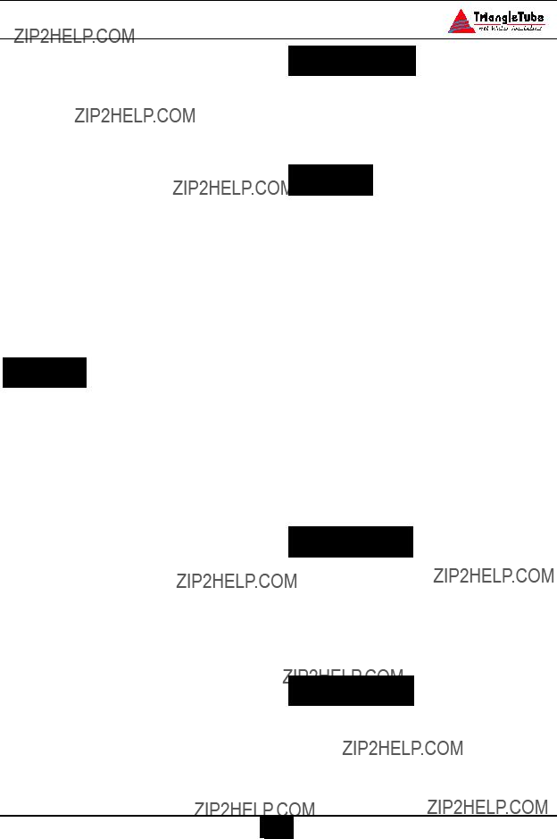
Setting Primary Thermostat Limit.
-The Primary (Space Heating) Thermostat located on the right side of the control panel acts as the high limit during the space heating function.
-Set the thermostat knob as shown in Fig. 22.
-Maximum limit setting is 180??F
NOTICE
NOTICE
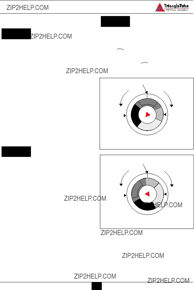
To adjust the thermostat settings:
- Turn thermostat knob clockwise  to increase water temperature
- Turn thermostat knob counter- clockwise  to decrease water temperature.
Fig. 22: Recommended Primary Thermostat
Setting
To ensure proper function of the limits the Primary Thermostat must be set higher than the Secondary Thermostat.
Adjustment of Secondary Thermostat Limit
-The Secondary (Domestic) Thermostat located on left side of the control panel maintains the minimum domestic water storage temperature.
-Set the thermostat knob as shown in Fig. 23.
-Maximum limit setting is 140??F.
Fig. 23: Recommended Secondary
Thermostat Setting

Setting the Thermostatic Mixing Valve
NOTICE
The thermostatic mixing valve controls the outlet hot water temperature deliv- ered to the faucets.
WARNING
POTENTIAL SCALD HAZARD The mixing valve must be installed on the ELITE. Removal of the mixing valve will create a potential scald hazard resulting in severe personal injury or death.
If any adjustment needs to be made on the valve:
-Use a L-Key to remove the set screw securing the knob to the valve.
-Remove the knob and lock ring from the valve.
-Replace the knob and adjust the set temperature of the valve to the desired temperature.
NOTICE
To calibrate the outlet temperature, allow the water to run for approximately 2 minutes and measure the water with a thermometer. To adjust the valve setting, rotate the knob clockwise to decrease the water temperature or counter-clockwise to increase the water temperature.
-Once the desired temperature is achieved, remove the knob and refit the lock ring onto the valve aligning the ring indicator mark with the valve???s ???Mix??? marking.
-Locate the tab on the inner face of the knob into the retainer in the locking ring. Secure the knob with setscrew.
-Record the valve performance on the Installation Record included in this manual.
DANGER
For proper operation of the thermostatic mixing valve, the manual valve on the U- tube assembly MUST remain open to avoid a potential scald hazard.

SECTION XIII- Check-Out Procedures
NOTICE
Perform the following check-out proce- dures as outlined and check off items as completed. When procedures are com- pleted, the installer should complete the installation record on page 45.
Check-out Procedures
Both inner and outer tanks filled with water.
Water chemistry checked and verified as outlined on page 37.
The automatic air vent on the unit and any place within the system are open one full turn.
Air is purged from the heating zones and primary system.
Domestic piping is purged of air and has been checked for leaks.
Thermostat circuit wiring checked and verified that no voltage is present to the Room Thermostat Snap-set as outlined on page 39.
Combustion levels and flame pattern verified as outlined on page 40.
Measure the rate of input on Natural Gas as outlined on page 41.
Primary and Secondary Thermostat properly set as shown in Fig. 22 and 23 page 42.
The thermostatic mixing valve adjusted to the desired domestic hot outlet tem- perature.
Adjusted balancing valves and system limit controls to provide design temper- atures to the primary space heating sys- tem.
In multiple zone applications, adjusted for correct flow of primary heating water to each zone.
Check and verified room thermostat function properly and the thermostat heat anticipator (if used) was properly set.
Observed several operating cycles for proper operation of the ELITE and the system.
Set the room thermostat(s) to the desired room temperature.
Reviewed all instructions shipped with the ELITE with the homeowner or maintenance personnel.
Complete the Installation Record on page 45.
Ensure all manuals and other documen- tation are returned to the Installation envelope and given to the owner for safekeeping.
Installation Record
SECTION XIV - Installation Record
The following items were completed during installation:
??????
 Installation instructions have been followed and completed
??????
 Check-out procedures have been followed and completed
?????? 
 Information regarding the unit and installation received and left with owner / maintenance ?????? personal.
Installer Information
(Company) ____________________________________________________________________
(Address) ____________________________________________________________________
(Address) ____________________________________________________________________
(Phone Number)_________________________________________________________________
45
SECTION XVII - Replacement Parts
Replacement Parts
WARNING
Replacement parts can be ordered and purchased through a local Triangle Tube distributor. When ordering parts, spec- ify the Model Number and Serial Number. Include a description of the part and a replacement part number. Using modified or other manufacturer parts will not be covered by warranty and may damage or cause improper function of the unit.
NOTICE
Refer to pages 47 and 49 for description and replacement part numbers.
6
4
3
7
10
5
8
Fig. 29: Top view of ELITE
1.Primary circuit, ?? 1??? NPT
2.Primary circuit drain valve connection, ?? 1/2??? NPT
3.Domestic temperature/pressure relief valve (150 psi), ?? 3/4??? NPT
4.Primary circuit & pressure relief valve (30 psi), ?? 1???
NPT
5.Domestic cold water inlet, ?? 3/4??? NPT
6.Hot water outlet & secondary thermostat sensor, ??
3/4??? NPT
7.Manual reset safety sensor & pressure indicator sen- sor, ?? 3/4??? NPT
8.Primary thermostat sensor, temperature indicator sensor and automatic reset safety sensor, ?? 1/2??? NPT
9.L.W.C.O. pressure sensor, ?? 1/2??? NPT (shown as Item 6 on page 47)
10.Primary circuit & air vent, ?? 1??? NPT
Specifications
Table 3: Dimensional Data
Graph 1: ELITE Pressure Loss - Primary Side
7
6
5
4
3
2
1
Flow Rate (gpm)
51
Additional quality water heating equipment available from
Triangle Tube/Phase III
Phase III Indirect Fired Water Heaters
- Exclusive ???Tank-in-Tank??? design - Stainless steel construction
- Available in 8 sizes and 2 models
- Limited LIFETIME residential warranty - 15 year limited commercial warranty
- Self cleaning/self descaling design
TTP Brazed Plate Heat Exchangers
- For domestic water, snow melting, radiant floor, refrigeration
- Plates made of stainless steel, with a 99.9 % copper and brazed, ensuring a high resistance to corrosion
- Self cleaning and self descaling
- Computerized sizing available from Triangle Tube/Phase III
- Available in capacities from 25,000 BTU/hr to 5,000,000 BTU/hr
Maxi-flo Pool and Spa Heat Exchangers
- Construction of high quality corrosion resistant stain- less steel (AISI 316)
- Specially designed built-in flow restrictor to assure maximum heat exchange
- Compact and light weight
- Available in 5 sizes that can accommodate any size pool or spa


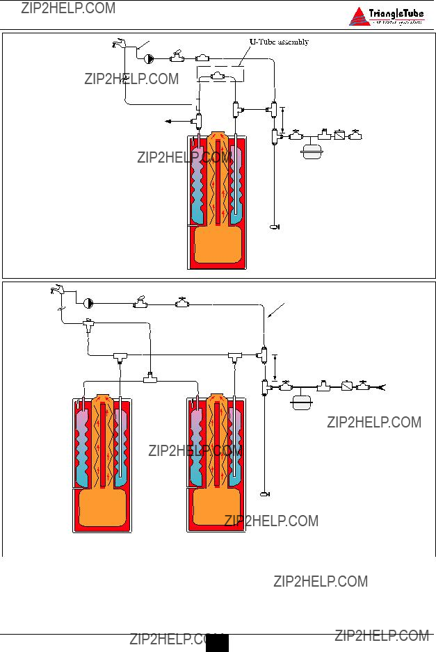


 1
1


 C
C


 8
8