10" Dual Bevel Compound
Power Miter Saw
(Model
PART NO. 901694 -
Copyright ?? 2001 Delta Machinery
please call
MANUAL INSTRUCTION
10" Dual Bevel Compound
Power Miter Saw
(Model
PART NO. 901694 -
Copyright ?? 2001 Delta Machinery
please call
MANUAL INSTRUCTION

GENERAL SAFETY RULES
Woodworking can be dangerous if safe and proper operating procedures are not followed. As with all machinery, certain hazards are involved with the operation of the product. Using the machine with respect and caution will considerably lessen the possibility of personal injury. However, if normal safety precautions are overlooked or ignored, personal injury to the oper- ator may result. Safety equipment such as guards, push sticks,
This machine was designed for certain applications only. DO NOT modify and/or use it for any application other than that for which it was designed. If you have questions relative to a particular application, DO NOT use the machine until you have first contacted Delta to determine if it can or should be performed on the product.
Technical Service Manager
Delta Machinery
4825 Highway 45 North
Jackson, TN 38305
(IN CANADA: 505 SOUTHGATE DRIVE, GUELPH, ONTARIO N1H 6M7)
WARNING: FAILURE TO FOLLOW THESE RULES MAY RESULT IN SERIOUS PERSONAL INJURY!
1.FOR YOUR OWN SAFETY, READ INSTRUCTION MANUAL BEFORE OPERATING THE TOOL. Learn the tool???s application and limitations as well as the specific hazards pecu- liar to it.
2.KEEP GUARDS IN PLACE and in working order.
3.ALWAYS WEAR EYE PROTECTION. Wear safety glasses. Everyday eyeglasses only have impact resistant lenses; they are not safety glasses. Also use face or dust mask if cutting operation is dusty. These safety glasses must conform to ANSI Z87.1 requirements. Note: Approved glasses have Z87 printed or stamped on them.
4.REMOVE ADJUSTING KEYS AND WRENCHES. Form a habit of checking to see that keys and adjusting wrenches are removed from tool before turning it ???on.
5.KEEP WORK AREA CLEAN. Cluttered areas and benches invite accidents.
6.DON???T USE IN DANGEROUS ENVIRONMENT. Don???t use power tools in damp or wet locations, or expose them to rain. Keep work area
7.KEEP CHILDREN AND VISITORS AWAY. All children and visitors should be kept a safe distance from work area.
8.MAKE WORKSHOP CHILDPROOF ??? with padlocks, master switches, or by removing starter keys.
9.DON???T FORCE TOOL. It will do the job better and be safer at the rate for which it was designed.
10.USE RIGHT TOOL. Don???t force tool or attachment to do a job for which it was not designed.
11.WEAR PROPER APPAREL. No loose clothing, gloves, neckties, rings, bracelets, or other jewelry to get caught in mov- ing parts. Nonslip footwear is recommended. Wear protective hair covering to contain long hair.
12.SECURE WORK. Use clamps or a vise to hold work when practical. It???s safer than using your hand and frees both hands to operate tool.
13.DON???T OVERREACH. Keep proper footing and balance at all times.
14.MAINTAIN TOOLS IN TOP CONDITION. Keep tools sharp and clean for best and safest performance. Follow instructions for lubricating and changing accessories.
15.DISCONNECT TOOLS before servicing and when chang- ing accessories such as blades, bits, cutters, etc.
16.USE RECOMMENDED ACCESSORIES. The use of accessories and attachments not recommended by Delta may cause hazards or risk of injury to persons.
17.REDUCE THE RISK OF UNINTENTIONAL STARTING. Make sure switch is in ???OFF??? position before plugging in power cord. In the event of a power failure, move switch to the ???OFF??? position.
18.NEVER STAND ON TOOL. Serious injury could occur if the tool is tipped or if the cutting tool is accidentally contact- ed.
19.CHECK DAMAGED PARTS. Before further use of the tool, a guard or other part that is damaged should be carefully checked to ensure that it will operate properly and perform its intended function ??? check for alignment of moving parts, bind- ing of moving parts, breakage of parts, mounting, and any other conditions that may affect its operation. A guard or other part that is damaged should be properly repaired or replaced.
20.DIRECTION OF FEED. Feed work into a blade or cutter against the direction of rotation of the blade or cutter only.
21.NEVER LEAVE TOOL RUNNING UNATTENDED. TURN POWER OFF. Don???t leave tool until it comes to a complete stop.
22.STAY ALERT, WATCH WHAT YOU ARE DOING, AND
USE COMMON SENSE WHEN OPERATING A POWER
TOOL. DO NOT USE TOOL WHILE TIRED OR UNDER
THE INFLUENCE OF DRUGS, ALCOHOL, OR MEDICA- TION. A moment of inattention while operating power tools may result in serious personal injury.
23.MAKE SURE TOOL IS DISCONNECTED FROM POWER SUPPLY while motor is being mounted, connected or
24.THE DUST GENERATED by certain woods and wood products can be injurious to your health. Always operate machinery in well ventilated areas and provide for proper dust removal. Use wood dust collection systems whenever possi- ble.
25.WARNING: SOME DUST CREATED BY
POWER SANDING, SAWING, GRINDING, DRILLING, AND OTHER CONSTRUCTION ACTIVITIES contains chemicals known to cause cancer, birth defects or other reproductive harm. Some examples of these chemicals are: ?? lead from
?? crystalline silica from bricks and cement and other masonry products, and
?? arsenic and chromium from
2
ADDITIONAL SAFETY RULES FOR
MITER SAWS
1.USE ONLY
2.DO NOT OPERATE the miter saw until it is completely assembled and installed according to the instructions.
3.IF YOU ARE NOT thoroughly familiar with the opera- tion of compound miter saws, obtain advice from your supervisor, instructor or other qualified person.
4.DO NOT perform any operation freehand. Secure or clamp workpiece firmly against fence.
5.KEEP HANDS OUT OF PATH of saw blade. If the workpiece you are cutting would cause your hand to be within hazard zone of the saw blade, the workpiece should be clamped in place before making cut.
6.BE SURE blade is sharp, runs freely and is free of vibration.
7.ALLOW the motor to come up to full speed before starting cut.
8.KEEP motor air slots clean and free of chips.
9.ALWAYS MAKE SURE all clamp handles are tight before cutting, even if the table is positioned in one of the positive stops.
10.BE SURE blade and flanges are clean and that arbor screw is tightened securely.
11.USE only blade flanges specified for your saw.
12.NEVER use blades larger or smaller in diameter than ten inches.
13.NEVER apply lubricants to the blade when it is running.
14.ALWAYS check the blade for cracks or damage prior to operating the tool. Replace cracked or damaged blades immediately.
15.NEVER use blades recommended for operation at less than 6000 RPM.
16.DO NOT operate the saw without guards in place.
17.ALWAYS keep the lower blade guard in place and operating properly.
18.NEVER reach around or behind saw blade.
19.MAKE SURE blade is not contacting workpiece before switch is turned on.
20.NEVER lock the switch in the ???ON??? position.
21.AFTER COMPLETING CUT, release power switch and wait for coasting blade to stop before returning saw to raised position.
22.TURN OFF tool and wait for saw blade to stop before moving workpiece or changing settings.
23.DO NOT remove jammed or
24.NEVER cut ferrous metals or masonry.
25.NEVER recut small pieces.
26.PROVIDE adequate support to the sides of the saw table for long workpieces.
27.NEVER use the miter saw in an area with flammable liquids or gases.
28.NEVER use solvents to clean plastic parts. Solvents could possibly dissolve or otherwise damage the material. Only a soft damp cloth should be used to clean plastic parts.
29.DISCONNECT power before changing blades or servicing.
30.DISCONNECT saw from power source and clean the machine before leaving it.
31.MAKE SURE the work area is clean before leaving the machine.
32.USING attachments and accessories other than those recommended by Delta may result in the risk of injuries.
33.MAKE SURE that the stabilizer bar is fully extended before operating the tool.
34.IMPORTANT: When the tool is not in use, the switch should be locked in the ???OFF??? position to prevent unauthorized use.
35.IF ANY PART of this tool is missing, damaged, or fails in any way, or if any electrical component fails to perform properly, shut off the switch and remove the plug from the power supply outlet. Replace missing, damaged or failed parts before resuming operation.
36.ADDITIONAL INFORMATION regarding the safe and proper operation of this product is available from the National Safety Council, 1121 Spring Lake Drive, Itasca, IL
SAVE THESE INSTRUCTIONS.
Refer to them often and use them to instruct others.
3

CONNECTING TOOL TO POWER SOURCE
POWER CONNECTIONS
A separate electrical circuit should be used for your tools. This circuit should not be less than #12 wire and should be protected with a 20 Amp time lag fuse. If an extension cord is used, use only
WARNING: DO NOT EXPOSE THE TOOL TO RAIN OR OPERATE THE TOOL IN DAMP LOCATIONS.
MOTOR SPECIFICATIONS
Your tool is wired for 120 volt, 60 HZ alternating current. Before connecting the tool to the power source, make sure the switch is in the ???OFF??? position. The
GROUNDING INSTRUCTIONS
WARNING: THIS TOOL MUST BE GROUNDED WHILE IN USE TO PROTECT THE OPERATOR FROM
ELECTRIC SHOCK.
1. All grounded,
In the event of a malfunction or breakdown, grounding pro- vides a path of least resistance for electric current to reduce the risk of electric shock. This tool is equipped with an elec- tric cord having an
Do not modify the plug provided - if it will not fit the outlet, have the proper outlet installed by a qualified electrician.
Improper connection of the
Check with a qualified electrician or service personnel if the grounding instructions are not completely understood, or if in doubt as to whether the tool is properly grounded.
Use only
Repair or replace damaged or worn cord immediately.
GROUNDED OUTLET BOX
CURRENT
CARRYING
PRONGS
2. Grounded,
If the tool is intended for use on a circuit that has an outlet that looks like the one illustrated in Fig. 1, the tool will have a grounding plug that looks like the plug illustrated in Fig. 1. A temporary adapter, which looks like the adapter illustrated in Fig. 2, may be used to connect this plug to a matching
NOTE: In Canada, the use of a temporary adapter is not permitted by the Canadian Electric Code.
NOTE: In Canada, the use of a temporary adapter is not permitted by the Canadian Electric Code.
WARNING: IN ALL CASES, MAKE CERTAIN THAT
THE RECEPTACLE IN QUESTION IS PROPERLY
GROUNDED. IF YOU ARE NOT CERTAIN, HAVE A
QUALIFIED ELECTRICIAN CHECK THE RECEPTACLE.
HOLES
GROUNDED OUTLET BOX
GROUNDING
MEANS
ADAPTER
GROUNDING BLADE
IS LONGEST OF THE 3 BLADES
HOLES
4

EXTENSION CORDS
Use proper extension cords. Make sure your extension cord is in good condition and is a
MINIMUM GAUGE EXTENSION CORD
RECOMMENDED SIZES FOR USE WITH STATIONARY ELECTRIC TOOLS
Fig. 3
OPERATING INSTRUCTIONS
FOREWORD
Delta Model
UNPACKING AND CLEANING
Carefully unpack the tool and all loose items from the shipping container(s). Remove the protective coating from all unpainted surfaces. This coating may be removed with a soft cloth moistened with kerosene (do not use acetone, gaso- line or lacquer thinner for this purpose). After cleaning, cover the unpainted surfaces with a good quality household floor paste wax.
5

CARTON CONTENTS
IMPORTANT: DO NOT LIFT THE MITER SAW BY THE
SWITCH HANDLE. THIS ACTION CAN CAUSE MIS-
ALIGNMENT. ALWAYS LIFT THE MACHINE BY THE
BASE OR CARRYING HANDLE.
1
Fig. 4
ASSEMBLY INSTRUCTIONS
WARNING: FOR YOUR OWN SAFETY, DO NOT CONNECT THE TOOL TO THE POWER SOURCE
UNTIL THE MACHINE IS COMPLETELY ASSEMBLED AND YOU READ AND UNDERSTAND THE
ENTIRE OWNER???S MANUAL.
ATTACHING TABLE LOCK HANDLE
1.Thread the table lock handle (A) Fig. 5, into the hole
(B) in the arm bracket (C).
2.Figure 6 illustrates the table lock handle (A) attached to the saw.
ROTATING TABLE TO
0 DEGREE POSITION
1.Loosen the table lock handle (A) Fig 6 one or two turns and depress the index lever (B).
2.Rotate the table to the left until the index stop engages with the 0 degree positive stop (Fig. 7). Tighten table lock handle (A).
A
C
B
Fig. 5
A
B
A
6

ATTACHING STOCK STOP
AND TABLE EXTENSIONS
1. Decide on which side of the saw table you want the stock stop (A) Fig. 8, and attach the stock stop (A) on the table extension (B).
2. Insert the ends of table extension (B) Fig. 9 into the two holes on the end of the saw base and into the two holes of retaining bracket (C). Tighten the screw (D) to hold the table extension in place.
3. Attach the left hand table extension (E) Fig. 10 in the same manner.
MOVING CUTTINGHEAD TO
THE UP POSITION
1. Push down on the switch handle, and pull out the cuttinghead lock knob (B) Fig. 11.
2. Move the cutting head to the up position (Fig. 12).
B
Fig. 11
A
B
Fig. 8
C
B
D
Fig. 9
E 
Fig. 10
Fig. 12
7
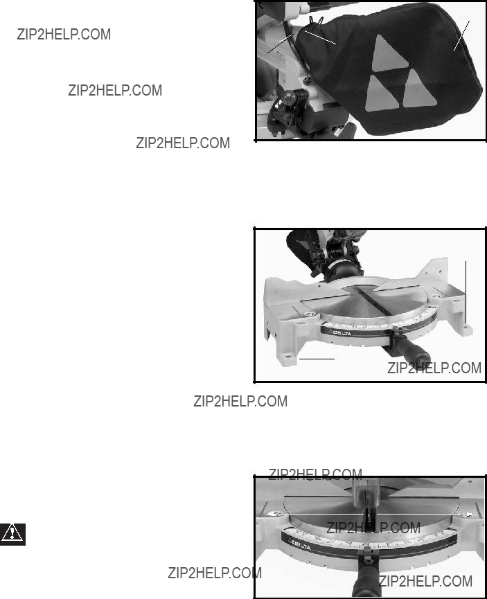
1. Attach the dust bag (A) Fig. 13, to the dust spout
(B). Be certain that the wire ring (C) is engaged in the spout groove.
A
C
Fig. 13
FASTENING MACHINE TO SUPPORTING SURFACE
Before operating this tool, firmly mount it to a sturdy workbench or other supporting surface. Four holes are provided, two of which are shown at (A) Fig. 14, for this purpose.
If the tool is to be moved frequently, mount it to a 3/4??? piece of plywood. Clamp the plywood to a supporting surface using ???C??? clamps.
A
A
Fig. 14
OPERATING CONTROLS AND ADJUSTMENTS
WARNING: THE AREA INSIDE THE TWO RED
LINES (A) FIG. 15 ON THE TABLE IS DESIGNATED
AS A HAZARD ZONE. NEVER PLACE YOUR
HANDS INSIDE THIS AREA WHILE OPERATING
THE TOOL.
Fig. 15
8

STARTING AND STOPPING THE MACHINE
To start the machine, squeeze the trigger (A) Fig. 16. To stop the machine, release the trigger.
This miter saw is equipped with an automatic electric blade brake. As soon as the trigger (A) Fig. 16, is released, the electric brake will be activated and will stop the blade in seconds.
WARNING: A TURNING SAW BLADE CAN BE HAZARDOUS. AFTER COMPLETING THE
CUT, RELEASE THE TRIGGER (A) FIG. 16 TO ACTIVATE THE BLADE BRAKE. KEEP THE
CUTTINGHEAD DOWN UNTIL THE BLADE HAS COME TO A COMPLETE STOP.
WARNING: THE TORQUE DEVELOPED DURING BRAKING MAY LOOSEN THE
ARBOR SCREW THAT HOLDS THE BLADE. CHECK THIS ARBOR SCREW OFTEN.
CAUTION: Prior to each operation, clean the blade area and underneath the table for chips and other debris. Such items can cause kickbacks and personal injury. Be certain that the machine is unplugged before making this inspection.
LOCKING SWITCH IN THE ???OFF??? POSITION
A
Fig. 16
B 
Fig. 17
IMPORTANT: When the tool is not in use, the switch should be locked in the ???OFF??? position, using a padlock (B) Fig. 17 with a 3/16" diameter shackle to prevent unauthorized use of the saw.
ROTATING TABLE FOR MITER CUTTING
The miter saw will cut any angle from a straight 0 degree cut to 47 degrees right and left. Loosen the lock handle (A) Fig. 18 one or two turns. Depress the index lever (B), and move the control arm. Tighten the lock handle at the desired angle.
This tool is equipped with positive stops at the 0, 22.5, 31.62, and 45 degree right and left positions. Simply loosen lock handle (A) Fig. 18, and move the control arm until the bottom of the index lever (B) engages into one of the positive stops (C). Tighten the lock handle (A). To disengage the positive stop, depress index lever (B) and move the handle.
The 31.62 positive stops aid in the cutting of crown molding. Refer to the ???CUTTING CROWN MOLDING??? section of this manual.
IMPORTANT: ALWAYS TIGHTEN LOCK HANDLE (A) FIG. 18 BEFORE CUTTING.
B A
C
Fig. 18
9

POINTER AND SCALE
A pointer (B) Fig. 19 indicates the actual angle of cut. Each line on the scale (C) represents 1 degree. When the pointer is rotated from one line to the next on the scale, the angle of cut is changed by 1 degree.
ADJUSTING POINTER
To adjust, loosen screw (D) Fig. 19, adjust the pointer, and tighten the screw (D).
TILTING CUTTINGHEAD FOR
BEVEL CUTTING
The cuttinghead of the saw can be tilted to cut any bevel angle from 0 degrees to 45 degrees, left or right. Loosen the bevel lock handle (A) Fig. 20, tilt the cutting arm to the desired angle, and tighten the lock handle.
Positive stops are provided to rapidly position the saw blade at 0 and 45 degrees to the table. Refer to the section of this manual titled ???ADJUSTING 0 AND 45 DEGREE BEVEL STOPS.??? The bevel angle of the cutting arm is determined by the position of the pointer (A) Fig. 21, on the scale (B). NOTE: Engage the 0 degree positive stop when making all cuts other than bevel cuts.
A triangle indicator is also provided on the bevel scale at the 33.85 degree bevel angle for cutting crown moulding. Refer to the ???CUTTING CROWN MOLDING??? section of this manual.
IMPORTANT: Engage 0 degree stop when not making bevel cuts.
IMPORTANT: See figs. 21A and 21B for correct hand position when bevel cutting. Be certain to always keep the hands outside of the table hazard area marked in red on the table. (See ???Table Hazard Area??? in ???OPERATING CONTROLS AND ADJUSTMENTS??? in this manual.
\Warning: Never cross the arms to bevel cut. Use Figs. 21A and 21B as examples when making bevel cuts.
AB A
CD 
Fig. 19
A 
Fig. 20
A
B
Fig. 21
10
A
A
REAR SUPPORT/CARRYING HANDLE
A rear stabilizer bar (A) Fig. 22, is provided to prevent the miter saw from tipping to the rear when the cuttinghead is returned to the up position after a cut has been made. For maximum support the bar (A) should be pulled out as far as possible.
 WARNING: BE CERTAIN THAT THE STABILIZER BAR IS FULLY EXTENDED WHEN MAKING CUTS.
The support bar (A) (Fig. 23) also acts as a carrying handle when transporting the saw.
ADJUSTING THE BLADE
PARALLEL TO TABLE SLOT
1.DISCONNECT TOOL FROM POWER SOURCE.
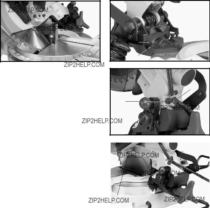
2.Lower the cutting arm. The saw blade (A) Fig. 24 should be parallel to the left edge (B) of the table opening.
3.Loosen the two socket head screws (B) Fig. 25, and remove the bevel cover (A) Fig. 25.
4.To adjust, loosen the three screws (A) Fig. 26, and move the cutting arm until the blade is parallel with the left edge (B) Fig. 24 of the table opening. Tighten the three screws (A) Fig. 26.
5.
 A
A
B
Fig. 24
A
A
B
11

ADJUSTING THE FENCE
90 DEGREES TO THE BLADE
The fence (A) Fig. 27 should be adjusted so that it is 90 degrees to the blade. To adjust:
1.DISCONNECT TOOL FROM POWER SOURCE.
2.First, adjust the blade so that it is parallel to the table slot.
3.Use a square (B) Fig. 27 with one end against the fence (A) and the other end against the slot in the table.
4.Loosen the four screws (C) Fig. 27, adjust the fence
90degrees to the table opening, and tighten the four screws (C).
C  B
B
A
C 
Fig. 27
ADJUSTING DOWNWARD
TRAVEL OF SAW BLADE
adjusted, tighten locknut (A) Fig. 28.
ADJUSTING 0 AND 45 DEGREE BEVEL STOPS
1.DISCONNECT TOOL FROM POWER SOURCE.
12
2.Set the saw blade on the ???0??? degree positive miter stop.
3.Use one end of a square (A) Fig. 29 on the table and the other end against the blade. Check to see if the blade is
0degrees to the table (Fig. 29).
4.If an adjustment is necessary, loosen the locknut (B) Fig. 30, and turn the screw (C) until head of the screw (C) contacts the 0 degree bevel stop (D) when the blade is 90 degrees to the table. Tighten locknut (B). NOTE: The bevel cover has been removed in Fig. 30 for clarity.
5.Loosen the bevel lock handle and move the cutting arm all the way to the left bevel position and tighten bevel lock handle.
6.Use a square (A) Fig. 31, to see if the blade is at 45 degrees to the table.
7.If not, loosen locknut (E) Fig. 32, and turn the screw (F) until the screw (F) contacts the 0 degree bevel stop when blade is 45 degrees to the table. Tighten locknut (E).
8.Repeat steps
A
Fig. 31
ADJUSTING TENSION
OF THE CUTTINGHEAD
RETURN SPRING
The tension of the cuttinghead return spring has been adjusted at the factory so that the cuttinghead returns to the up position after a cut has been made. However, to re- adjust the spring tension:
1. DISCONNECT TOOL FROM POWER SOURCE.
Loosen the locknut (A) Fig. 33, and turn the screw (B) clockwise to increase or counterclockwise to decrease the spring tension. After the spring tension has been adjusted, tighten locknut (A).
F
E
Fig. 32
B
A
Fig. 33
Fig. 34
13

TYPICAL OPERATIONS AND HELPFUL HINTS
1.Before cutting, be certain that the cutting arm and table are at their correct settings and are firmly locked in place. Also, determine that the workpiece is the right size for the saw.
2.Firmly clamp the workpiece to the table against the fence. Fig. 35 illustrates the work clamp (A) used to clamp the workpiece to the fence. The clamp (A) can also be used on the right side of the machine.
3.For best results, cut at a slow, even cutting rate.
4.WARNING: If the workpiece causes your hand to be within the hazard zone of of the saw blade, clamp the workpiece in place before making the cut (Fig. 35.)
5. Never attempt freehand cutting (wood that is not held firmly against the fence and table).
AUXILIARY WOOD FENCE
WARNING: When performing multiple or  repetitive
An auxiliary wood fence can help minimize the danger.
Holes are provided in the fence (A) Fig. 36 to attach an auxiliary fence. This auxiliary fence is constructed of straight wood approximately 1/2 inch thick by 3 inches high by 20 inches long. NOTE: The auxiliary fence (A) is used ONLY with the saw blade in the 0 degree bevel position (90 degrees to the table). When bevel cutting (blade tilted) the auxiliary fence will have to be removed.
CUTTING ALUMINUM
Aluminum extrusions such as used for making aluminum screens and storm windows can be cut with the com- pound miter saw. Position the material so the blade is cutting through the smallest
A
Fig. 35
A
A
Fig. 36
BLADE
FENCE
RIGHT
Fig. 37
blade.
WARNING: NEVER APPLY LUBRICANT TO
FENCE
BLADE
THE BLADE WHILE THE TOOL IS RUNNING.
WRONG
Fig. 38
14

CUTTING BOWED MATERIAL
If the workpiece is bowed, position it on the table with the bowed part up and against the fence (Fig. 39).
If the material is positioned the wrong way (Fig. 40), the workpiece will pinch the blade near the completion of the cut.
CUTTING CROWN MOLDING
One of the many features of a compound miter saw is the ease of cutting crown molding. The following is an example of cutting both inside and outside corners on 52/38 degree wall angle crown molding. NOTE: When cutting 45 degree wall angle crown molding, follow the same procedure for both inside and outside corners. The only difference will be that the bevel position will always be at 30 degrees but the miter position will be 35.25 degrees to the right or left.
1.Move the table to the 31.62 degree right miter position and lock the table in position. NOTE: A positive stop is provided to find this angle quickly.
2.Tilt the saw blade to the 33.85 degree left bevel position and tighten bevel lock handle. NOTE: A triangle indicator is provided on the bevel scale to find this angle quickly.
3.Place the crown molding on the table with the CEILING EDGE of the molding against the fence, and make the cut (Fig. 41). NOTE: The piece of crown molding used for the outside corner will always be on the right hand side of the blade,(A) Fig. 41. The piece of crown molding used for the inside corner will always be on the left hand side of the blade, (B) Fig. 41.
4.To make the matching halves of the inside and outside corners, rotate the table to the 31.62 degree left miter posi- tion and tighten table lock handle. NOTE: A positive stop is provided to find this angle quickly.
5.Place the crown molding on the table with the WALL EDGE of the crown molding against the fence and make the cut. Again, the piece of crown molding used for the outside corner will always be on the right side of the blade, (C) Fig.
42.The piece of crown molding used for the inside corner will always be on the left side of the blade (D) Fig. 42
6.Fig. 43 illustrates the two outside corner pieces.
7.Fig. 44 illustrates the two inside corner pieces.
BA
DC
15

D
CA
B
MAINTENANCE
CHANGING THE BLADE
WARNING: USE ONLY
TAIN THAT THEY HAVE A NEGATIVE HOOK ANGLE. USE ONLY 10??? DIAMETER SAW BLADES RATED FOR 6000 RPM OR HIGHER AND HAVE 5/8??? DIAMETER ARBOR HOLES.
1.DISCONNECT TOOL FROM POWER SOURCE.
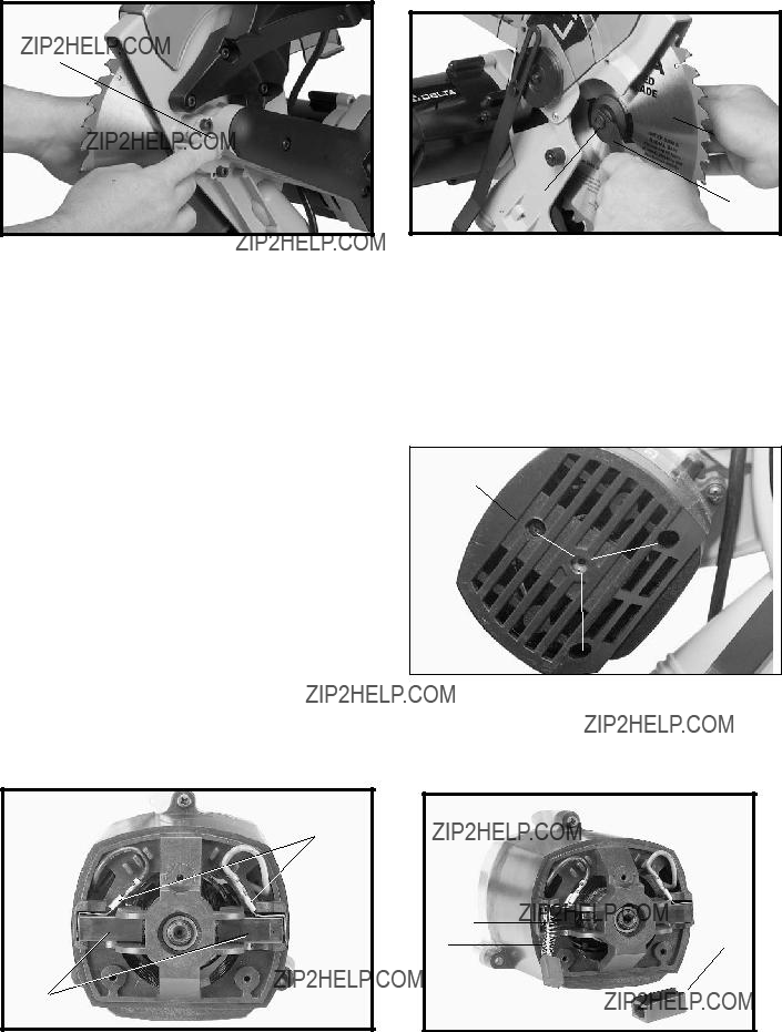
2.Remove the screw (A) Fig. 45, and rotate the cover
(B) to the rear (Fig. 46).
3.Depress the arbor lock (A) Fig. 47, to keep the blade from turning.
4.Use the supplied wrench (D) Fig. 48 to loosen the
6.Attach the new blade. BE CERTAIN THAT THE
TEETH OF THE SAW BLADE ARE POINTING DOWN AT THE FRONT. Use the supplied wrench to attach the outside blade flange (F) Fig. 48, and the arbor screw (E). At the same time, depress the arbor lock to keep the blade from turning.
7.Replace the screw and cover (moved to the rear in STEP 2).
ADJUSTING BLADE GUARD
1.After an extended period of time, the movable blade guard (B) Fig. 45 might move erratically when the cuttinghead is lowered. This can be easily corrected by slightly tightening the nut (C) Fig. 45 until the lower blade guard moves smoothly.
2.As soon as the cuttinghead begins to lower, the lower blade guard (B) Fig. 45 should begin to move. If it does not, loosen the nut (C) slightly until the blade guard
(B) moves smoothly.
B 
Fig. 46
16
A
Fig. 47
BRUSH INSPECTION
AND REPLACEMENT
CAUTION: BEFORE INSPECTING THE BRUSHES,
DISCONNECT THE TOOL FROM THE POWER
SOURCE.
Brush life varies, depending on the load on the motor. Check the brushes after the first 50 hours of use for a new machine, or after a new set of brushes has been installed. After the first check, examine them after about every 10 hours of use until replacement is necessary. To inspect the brushes:
1.Remove three screws (A) Fig. 49, and remove motor cover (B).
2.The brushes are located in the two holders (C) Fig. 50. Remove spade type terminal connectors (D) and pull out brush holders (C).
3.Fig. 51 illustrates one of the brushes (E) removed from the holder (C). When the carbon on either brush (E) is worn to 3/16??? in length or if either spring (F) or shunt wire (G) (beneath spring) is burned or damaged in any way, replace both brushes. If the brushes are found serviceable after removing, reinstall them in the same position as removed.
D
C
Fig. 50
F G
G
ED
Fig. 48
B
A
Fig. 49
G
FC
E 
Fig. 51
17

ACCESSORIES
A complete line of accessories is available from your Delta Supplier,
WARNING: Since accessories other than those offered by Delta have not been tested with this product, use of such accessories could be hazardous. For safest operation, use only Delta recommended accessories with this product.
PARTS, SERVICE OR WARRANTY ASSISTANCE
All Delta Machines and accessories are manufactured to high quality standards and are serviced by a network of
Two Year Limited Warranty
Delta will repair or replace, at its expense and at its option, any Delta machine, machine part, or machine accessory which in normal use has proven to be defective in workmanship or material, provided that the customer returns the product pre- paid to a Delta factory service center or authorized service station with proof of purchase of the product within two years and provides Delta with reasonable opportunity to verify the alleged defect by inspection. Delta may require that electric motors be returned prepaid to a motor manufacturer???s authorized station for inspection and repair or replacement. Delta will not be responsible for any asserted defect which has resulted from normal wear, misuse, abuse or repair or alteration made or specifically authorized by anyone other than an authorized Delta service facility or representative. Under no cir- cumstances will Delta be liable for incidental or consequential damages resulting from defective products. This warranty is Delta???s sole warranty and sets forth the customer???s exclusive remedy, with respect to defective products; all other war- ranties, express or implied, whether of merchantability, fitness for purpose, or otherwise, are expressly disclaimed by Delta.
Printed in U.S.A.
18

(CENTROS DE SERVICIO DE
Parts and Repair Service for
Authorized Service Stations are located in many large cities. Telephone
CANADIAN
The following are trademarks of
INNOVATION THAT WORKS??, JETSTREAM??, LASERLOC??, OMNIJIG??, POCKET CUTTER??,
CABLE??, QUICKSAND??, SANDTRAP??, SAW BOSS??,
AL EDGE??, THE PROFESSIONAL SELECT??, TIGER CUB??, TIGER SAW??, TORQBUSTER??, WHISPER SERIES??, DURATRONIC???, FLEX???, FRAME SAW???,
Trademarks noted with ??? and ?? are registered in the United States Patent and Trademark Office and may also be registered in other coun- tries. Las Marcas Registradas con el signo de ??? y ?? son registradas por la Oficina de Registros y Patentes de los Estados Unidos y tam- bi??n pueden estar registradas en otros pa??ses.Printed in U.S.A.
36