6" Professional Jointer
(Model
PART NO. 909995 -
Copyright ?? 2003 Delta Machinery
To learn more about DELTA MACHINERY
visit our website at: www.deltamachinery.com.
For Parts, Service, Warranty or other Assistance,
please call
MANUAL INSTRUCTION
6" Professional Jointer
(Model
PART NO. 909995 -
Copyright ?? 2003 Delta Machinery
To learn more about DELTA MACHINERY
visit our website at: www.deltamachinery.com.
For Parts, Service, Warranty or other Assistance,
please call
MANUAL INSTRUCTION

SAFETY GUIDELINES / DEFINITIONS
This manual contains information that is important for you to know and understand. This information relates to protect- ing YOUR SAFETY and PREVENTING EQUIPMENT PROBLEMS. To help you recognize this information, we use the symbols to the right. Please read the manual and pay attention to these sections.
 Indicates an imminently hazardous situation which, if not avoided, will result in death or serious injury. Indicates a potentially hazardous situation which, if not avoided, could result in death or serious injury.
Indicates a potentially hazardous situation which, if not avoided, may result in minor or moderate injury
Used without the safety alert symbol indicates potentially hazardous situation which, if not avoided, may result in property damage.
 SOME DUST CREATED BY POWER SANDING, SAWING, GRINDING, DRILLING, AND OTHER CONSTRUCTION ACTIVITIES contains chemicals known to cause cancer, birth defects or other reproductive harm. Some examples of these chemicals are:
??lead from
??crystalline silica from bricks and cement and other masonry products, and
??arsenic and chromium from
Your risk from these exposures varies, depending on how often you do this type of work. To reduce your exposure to these chemicals: work in a well ventilated area, and work with approved safety equipment, such as those dust masks that are specially designed to filter out microscopic particles.
GENERAL SAFETY RULES
Woodworking can be dangerous if safe and proper operating procedures are not followed. As with all machinery, there are certain hazards involved with the operation of the product. Using the machine with respect and caution will considerably lessen the possibility of personal injury. However, if normal safety precautions are overlooked or ignored, personal injury to the operator may result. Safety equipment such as guards, push sticks,
This machine was designed for certain applications only. Delta Machinery strongly recommends that this machine not be modified and/or used for any application other than that for which it was designed. If you have any questions relative to a particular application, DO NOT use the machine until you have first contacted Delta to determine if it can or should be performed on the product.
Technical Service Manager
Delta Machinery
4825 Highway 45 North
Jackson, TN 38305
(IN CANADA: 505 SOUTHGATE DRIVE, GUELPH, ONTARIO N1H 6M7)
Read Operator???s Manual. Do not operate equipment until you have read Operator???s Manual for Safety,
Assembly, Operation, and Maintenance Instructions.
FAILURE TO FOLLOW THESE RULES MAY RESULT IN SERIOUS PERSONAL INJURY
1.FOR YOUR OWN SAFETY, READ INSTRUCTION MANUAL BEFORE OPERATING THE TOOL. Learn the tool???s application and limitations as well as the specific hazards peculiar to it.
2.KEEP GUARDS IN PLACE and in working order.
3.ALWAYS WEAR EYE PROTECTION. Wear safety glasses. Everyday eyeglasses only have impact resistant lenses; they are not safety glasses. Also use face or dust mask if cutting operation is dusty. These safety glasses must conform to ANSI Z87.1 requirements. NOTE: Approved glasses have Z87 printed or stamped on them.
4.REMOVE ADJUSTING KEYS AND WRENCHES. Form habit of checking to see that keys and adjusting wrenches
are removed from tool before turning it ???on???.
5.KEEP WORK AREA CLEAN. Cluttered areas and benches invite accidents.
6.DON???T USE IN DANGEROUS ENVIRONMENT. Don???t use power tools in damp or wet locations, or expose them to rain. Keep work area
7.KEEP CHILDREN AND VISITORS AWAY. All children and visitors should be kept a safe distance from work area.
8.MAKE WORKSHOP CHILDPROOF ??? with padlocks, master switches, or by removing starter keys.
9. DON???T FORCE TOOL. It will do the job better and be safer at the rate for which it was designed.
10.USE RIGHT TOOL. Don???t force tool or attachment to do a job for which it was not designed.
11.WEAR PROPER APPAREL. No loose clothing, gloves, neckties, rings, bracelets, or other jewelry to get caught in moving parts. Nonslip footwear is recommended. Wear protective hair covering to contain long hair.
12.SECURE WORK. Use clamps or a vise to hold work when practical. It???s safer than using your hand and frees both hands to operate tool.
13.DON???T OVERREACH. Keep proper footing and balance at all times.
14.MAINTAIN TOOLS IN TOP CONDITION. Keep tools sharp and clean for best and safest performance. Follow instructions for lubricating and changing accessories.
15.DISCONNECT TOOLS before servicing and when changing accessories such as blades, bits, cutters, etc.
16.USE RECOMMENDED ACCESSORIES. The use of accessories and attachments not recommended by Delta may cause hazards or risk of injury to persons.
2

17.REDUCE THE RISK OF UNINTENTIONAL STARTING. Make sure switch is in ???OFF??? position before plugging in power cord. In the event of a power failure, move switch to the ???OFF??? position.
18.NEVER STAND ON TOOL. Serious injury could occur if the tool is tipped or if the cutting tool is accidentally contacted.
19.CHECK DAMAGED PARTS. Before further use of the tool, a guard or other part that is damaged should be carefully checked to ensure that it will operate properly and perform its intended function ??? check for alignment of moving parts, binding of moving parts, breakage of parts, mounting, and any other conditions that may affect its operation. A guard or other part that is damaged should be properly repaired or replaced.
20.DIRECTION OF FEED. Feed work into a blade or cutter against the direction of rotation of the blade or cutter only.
21.NEVER LEAVE TOOL RUNNING UNATTENDED. TURN POWER OFF. Don???t leave tool until it comes to a complete stop.
22.STAY ALERT, WATCH WHAT YOU ARE DOING, AND
USE COMMON SENSE WHEN OPERATING A POWER
TOOL. DO NOT USE TOOL WHILE TIRED OR UNDER
THE INFLUENCE OF DRUGS, ALCOHOL, OR MEDICATION. A moment of inattention while operating power tools may result in serious personal injury.
23.MAKE SURE TOOL IS DISCONNECTED FROM POWER SUPPLY while motor is being mounted, connected or reconnected.
24.THE DUST GENERATED by certain woods and wood products can be injurious to your health. Always operate machinery in well ventilated areas and provide for proper dust removal. Use wood dust collection systems whenever possible.
ADDITIONAL SAFETY RULES FOR JOINTERS
FAILURE TO FOLLOW THESE RULES MAY RESULT IN SERIOUS PERSONAL INJURY.
1.WARNING: Do not operate the jointer until it is completely assembled and installed according to the instructions.
2.IF YOU ARE NOT thoroughly familiar with the oper- ation of jointers, obtain advice from your supervisor, instructor or other qualified person.
3.KEEP cutterhead sharp and free of all rust and pitch.
4.BEFORE starting machine, check cutterhead guard to make sure it is not damaged and operates freely.
5.ALWAYS make sure exposed cutterhead behind the fence is guarded, especially when jointing near the edge.
6.NEVER perform jointing or surfacing operations with the cutterhead guard removed.
7.MAKE CERTAIN the infeed and outfeed tables are tightened before starting the machine.
8.NEVER start the jointer with the workpiece contacting the cutterhead.
9.ALWAYS hold the workpiece firmly against the tables and fence.
10.NEVER perform any operation
11.AVOID awkward operations and hand positions where a sudden slip could cause your hand to move into the cutterhead.
12.ALWAYS use
13.DO NOT perform jointing operations on material shorter than 10 inches, narrower than 3/4 inch or less than 1/2 inch thick.
14.DO NOT perform surfacing operations on material shorter than 10 inches, narrower than 3/4 inch, wider than 6 inches or less than 1/2 inch thick.
15.NEVER make jointing or surfacing cuts deeper than 1/8 inch. On cuts more than
16.MAINTAIN the proper relationship of infeed and outfeed table surfaces and cutterhead knife path.
17.SUPPORT the workpiece adequately at all times during operation; maintain control of the work at all times.
18.DO NOT back the workpiece toward the infeed table.
19.DO NOT attempt to perform an abnormal or little- used operation without study and the use of adequate
20.SHUT OFF power before servicing or adjusting jointer.
21.DISCONNECT jointer from power source and clean the machine before leaving it.
22.MAKE SURE the work area is clean before leaving the machine.
23.SHOULD any part of your jointer be missing, damaged, or fail in any way, or any electrical component fail to perform properly, shut off switch and remove plug from power supply outlet. Replace missing, damaged or failed parts before resuming operation.
24.THE USE of attachments and accessories not recommended by Delta may result in the risk of injuries.
25.ADDITIONAL INFORMATION regarding the safe and proper operation of this product is available from the National Safety Council, 1121 Spring Lake Drive, Itasca, IL
SAVE THESE INSTRUCTIONS. Refer to them often
and use them to instruct others.
3

POWER CONNECTIONS
A separate electrical circuit should be used for your machines. This circuit should not be less than #12 wire and should be protected with a 20 Amp time lag fuse. If an extension cord is used, use only
 DO NOT EXPOSE THE MACHINE TO RAIN OR OPERATE THE MACHINE IN DAMP LOCATIONS.
MOTOR SPECIFICATIONS
Your machine is wired for 120 volt, 60 HZ alternating current. Before connecting the machine to the power source, make sure the switch is in the ???OFF??? position.
GROUNDING INSTRUCTIONS
 THIS MACHINE MUST BE GROUNDED WHILE IN USE TO PROTECT THE OPERATOR FROM
ELECTRIC SHOCK.
1. All grounded,
In the event of a malfunction or breakdown, grounding provides a path of least resistance for electric current to reduce the risk of electric shock. This machine is equipped with an electric cord having an equipment- grounding conductor and a grounding plug. The plug must be plugged into a matching outlet that is properly installed and grounded in accordance with all local codes and ordinances.
Do not modify the plug provided - if it will not fit the outlet, have the proper outlet installed by a qualified electrician.
Improper connection of the
Check with a qualified electrician or service personnel if the grounding instructions are not completely understood, or if in doubt as to whether the machine is properly grounded.
Use only
Repair or replace damaged or worn cord immediately.
GROUNDED OUTLET BOX
CURRENT
CARRYING
PRONGS
2. Grounded,
If the machine is intended for use on a circuit that has an outlet that looks like the one illustrated in Fig. A, the machine will have a grounding plug that looks like the plug illustrated in Fig. A. A temporary adapter, which looks like the adapter illustrated in Fig. B, may be used to connect this plug to a matching
NOTE: In Canada, the use of a temporary adapter is not permitted by the Canadian Electric Code.
3. Grounded,
If the machine is intended for use on a circuit that has an outlet that looks like the one illustrated in Fig. C, the machine will have a grounding plug that looks like the plug illustrated in Fig. C. Make sure the machine is connected to an outlet having the same configuration as
GROUNDED OUTLET BOX
GROUNDING
MEANS
ADAPTER
GROUNDING BLADE
IS LONGEST OF THE 3 BLADES
4

the plug. No adapter is available or should be used with this machine. If the machine must be
 I N A L L C A S E S , M A K E C E RTA I N
THE RECEPTACLE IN QUESTION IS PROPERLY
GROUNDED. IF YOU ARE NOT SURE HAVE A
Q U A L I F I E D E L E C T R I C I A N C H E C K T H E
RECEPTACLE.
GROUNDED OUTLET BOX
CURRENT
CARRYING
PRONGS
GROUNDING BLADE
IS LONGEST OF THE 3 BLADES
Fig. C
EXTENSION CORDS
 Use proper extension cords. Make sure your extension cord is in good condition and is a
MINIMUM GAUGE EXTENSION CORD
RECOMMENDED SIZES FOR USE WITH STATIONARY ELECTRIC MACHINES
MINIMUM GAUGE EXTENSION CORD
RECOMMENDED SIZES FOR USE WITH STATIONARY ELECTRIC MACHINES
OPERATING INSTRUCTIONS
FOREWORD
Delta Model
UNPACKING AND CLEANING
Carefully unpack the machine and all loose items from the shipping container(s). Remove the protective coating from all unpainted surfaces. This coating may be removed with a soft cloth moistened with kerosene (do not use acetone, gasoline or lacquer thinner for this purpose). After cleaning, cover the unpainted surfaces with a good quality household floor paste wax.
NOTICE: THE MANUAL COVER PHOTO ILLUSTRATES THE CURRENT
PRODUCTION MODEL. ALL OTHER ILLUSTRATIONS ARE REPRESENTATIVE
ONLY AND MAY NOT DEPICT THE ACTUAL COLOR, LABELING OR
ACCESSORIES AND MAY BE INTENDED TO ILLUSTRATE TECHNIQUE ONLY.
5
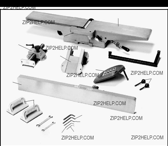
JOINTER PARTS
1
2
3
4 
5
6
7
7.Fence
8.Push Blocks (2)
6

19
18
ASSEMBLY
FOR YOUR OWN SAFETY, DO NOT CONNECT THE MACHINE TO THE POWER SOURCE UNTIL
THE MACHINE IS COMPLETELY ASSEMBLED AND YOU READ AND UNDERSTAND THE ENTIRE
INSTRUCTION MANUAL.
STAND AND ELECTRICALS
Fig. 6
7

ASSEMBLING
JOINTER TO STAND
1.The outfeed end (N) Fig. 9, of the jointer must be pointing toward the end of the stand with dust chute opening (B) Fig. 7.
2.Remove three screws (C) Fig. 7, and loosen two screws (D). Then remove back panel (E) from stand by lifting upward.
3. Line up the three holes (F) Fig. 8, on the top of stand with the three threaded holes on the bottom of the jointer base. Using the supplied 8mm hex wrench (G) Fig. 9, fasten the jointer to the stand. Place a M10.2 lockwasher (I), on a M10x1.5x20mm hex socket head screw (H), and a M10 flat washer onto the screw. Insert the screw through the hole in the stand and thread the screw into the tapped hole in the bottom of the jointer, and tighten securely. Repeat this process for the two remaining holes in the stand and the jointer. NOTE: The mounting hole located on the dust chute end of the stand is accessed by reaching up through the dust chute.
ASSEMBLING
MOTOR PULLEY
Assemble motor pulley (K) Fig. 10, to motor shaft with the hub of the pulley in the outer position as shown. Make certain key (L) is inserted in the keyway of the pulley and motor shaft, then tighten set screw (M) using the 2.5mm hex wrench (not shown).
B
C
E
D
Fig. 7
F
Fig. 8
G J N
I
H
Fig. 9
M  K
K
L
Fig. 10
8

ASSEMBLING BELT AND
ALIGNING PULLEYS
1.Place belt (A) Fig. 11, in groove of cutterhead pulley
(B) and motor pulley (C).
2.Make certain the motor pulley (C) Figs. 11 and 12, is properly aligned with cutterhead pulley (B) by placing a straight edge (D) Fig. 12, onto the face of each pulley as shown.
3.If an adjustment is needed, the motor pulley can be moved in or out on the motor shaft, or the motor can be shifted by loosening motor mounting screws, two of which are shown at (E) Fig. 11. After adjustments are made, tighten motor mounting hardware and motor pulley set screw.
ADJUSTING BELT TENSION
1.Correct belt tension is obtained when there is approximately 1" deflection at the center span of the belt using light finger pressure.
2.If an adjustment is required, the motor can be raised or lowered to obtain the correct belt tension.
3.Tighten motor mounting hardware after tension is applied, making sure alignment of the pulleys is not disturbed.
4.
ASSEMBLING CUTTERHEAD
PULLEY GUARD/CARRIAGE
MOUNTING BRACKET
1.Position two alignment pins (A) Fig. 13, with two alignment holes (B) in jointer base.
2.Using the supplied 6mm hex wrench (E) Fig. 14, fasten bracket (C) onto jointer base (G). Place a M8.1 lockwasher then an M8 flat washer on an M8x1.25x55mm hex socket head screw. Insert the screw (D) Fig. 14, through the hole in bracket (C), and thread the screw into the jointer base (B) Fig. 13, and tighten securely. Repeat this process for the three remaining holes in the bracket and jointer.
B
A
E
C
Fig. 11
B
D
C
Fig. 12
C
 B
B
A
Fig. 13
C
GD  E
E
Fig. 14
9

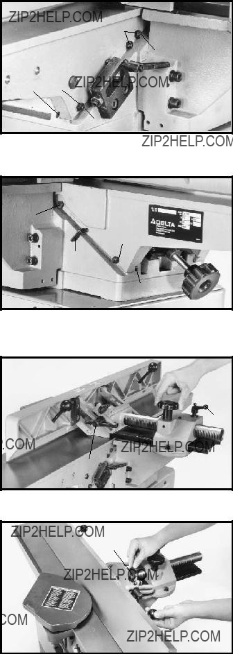
ASSEMBLING FENCE
CARRIAGE ASSEMBLY
1.Fasten fence carriage assembly (A) Fig. 15, to cutterhead pulley guard/carriage mounting bracket (C). Align the holes in the fence carriage assembly (A) one of which is shown at (D), with the holes in the pulley guard/carriage mounting bracket (C). Place a M8.1 lockwasher (E), then an M8 flat washer on an M8x1.25x20mm hex socket head screw (B). Insert the screw through the hole in the fence carriage assembly, and thread the screw into the tapped hole in the cutterhead pulley guard/carriage mounting bracket and tighten securely. Repeat this process for the remaining hole in the fence carriage assembly and the cutterhead pulley guard/carriage mounting bracket.
2.Fig. 16, illustrates fence carriage assembly properly mounted.
 A
A
D
FE
 C
C
B
Fig. 15
ASSEMBLING FENCE
1.Fasten fence (A) Fig. 17, to fence carriage assembly
(C) through holes (D). Align the two holes (G) in the fence with the two holes (D) in the carriage assembly (C). Place a M8.1 lockwasher (E), then an M8 flat washer (F), on an M8x1.25x25mm hex socket head screw (B). Insert the screw through hole (D) in the carriage assembly and thread the screw into the tapped hole (G) in the fence, and tighten securely. Repeat this process for the remaining hole in the fence and carriage assembly.
2.Fig. 18 illustrates fence properly mounted.
3.Thread shorter fence handle (E ) Fig.19, into infeed end of fence (A) and longer fence handle (G) into outfeed end as shown.
Fig. 16
A
G
 C
C
F
E BD
Fig. 17
G
E
A
10
ASSEMBLING
CUTTERHEAD GUARD
1.Remove set screw (A) Fig. 20 from cutterhead guard post (F) with the 2.5mm hex wrench. Insert post (F) through hole in the infeed table. NOTE: A spring is supplied in knob assembly (E) that returns the guard (C) over the cutterhead after a cut has been made. Turn knob (E)
2.Thread set screw (A) Fig. 21 back into post (F) Fig. 20, to keep cutterhead guard (C) in position during jointer operation.
3.Fig. 21, illustrates the cutterhead guard (C) assembled to the infeed table.
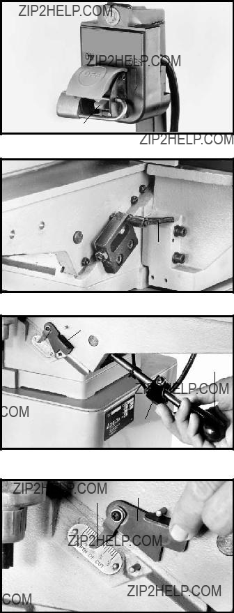
ASSEMBLING SWITCH AND
MOUNTING BRACKET
1.Align the two holes in the switch mounting bracket
(A) Fig 22, with the two holes (D) in the back of the infeed table (B). Place an M8 flat washer (E) Fig. 22, on an M8x1.25x30mm hex socket head screw (C). Insert the screw through the hole (D) Fig. 22, in the switch mounting bracket (A) and the hole in the back of the infeed table (B). Place a M8.1 lockwasher (F) Fig. 22, onto the screw (C). Thread a M8x1.25 hex nut (G) Fig. 22, onto the screw (C) and tighten securely. Repeat this process for the remaining hole in the switch mounting bracket and the infeed table.
2.Align the hole in the switch (E) Fig. 23, with the hole
(G) in the mounting bracket. Place an 11/32" flat washer
(I) Fig. 23, on a
3.Fig. 24, illustrates the switch properly mounted.
G
A
E
K
H I J
Fig. 23
C
F
A
E
D
Fig. 20
C
A
Fig. 21
 A
A
E C
F
G
B D
Fig. 22
Fig. 24
11

ASSEMBLING DUST CHUTE
The jointer stand has a
A standard 4" dust collection hose can be attached to dust collector connector.
C
OPERATING CONTROLS AND ADJUSTMENTS
STARTING AND STOPPING
JOINTER
1.The on/off switch is located underneath the switch shield (B) Fig. 31. To start the jointer, move switch (A) up to the ???ON??? position.
2.To turn the jointer ???OFF???, push down on switch shield (B) Fig. 32, as shown.
B
A
Fig. 31
B
Fig. 32
12
LOCKING SWITCH
IN THE ???OFF??? POSITION
IMPORTANT: When the tool is not in use, the switch should be locked in the ???OFF??? position to prevent unauthorized use. Insert the shank of padlock (C) Fig. 33, through the holes in the switch plate to lock the on/off switch trigger (A).
INFEED TABLE
ADJUSTMENTS
1. To raise or lower the infeed table, loosen table lock handle (A) Fig. 34, located on the rear side of infeed table.
2.Grasp the infeed table raising/lowering handle (B) Fig. 35, and squeeze locking lever (C), and raise or lower handle (B).
3.NOTE: When raising or lowering the infeed table, a depth stop (D) Figs. 35 and 36, will automatically stop the table at an 1/8"
 Always make sure table lock handle (A) Fig. 34, is tightened before operation. The table lock handle (A) is
C 
A
Fig. 33
A
Fig. 34
D
B
C
Fig. 35
4. The
E
D
Fig. 36
13

INFEED TABLE
POSITIVE STOPS
D I S C O N N E C T M A C H I N E F R O M
POWER SOURCE.
Positive stops are provided to limit the height and depth of the infeed table. To adjust the stops, loosen two locknuts (F) and (G) Fig. 37, and turn the two adjusting screws (J) and (K) as required. Then retighten the locknuts (F) and (G). A good suggestion is to set the upper positive stop (J) for your finish or final cut. This means that you will be able to rapidly set the infeed table for a finish or final cut without checking the scale and pointer. Also the lower positive stop (K) can be set for the maximum
OUTFEED TABLE
ADJUSTMENTS
D I S C O N N E C T M A C H I N E F R O M
POWER SOURCE.
1.In order to perform accurate jointing operations, the outfeed table must be exactly level with the knives at their highest point of revolution. This means that the knives must be parallel to the outfeed table and project equally from the cutterhead.
2.To move the outfeed table up or down, loosen lock- screw (A) Fig. 38, and turn hand knob (B). When the outfeed table is exactly level with the knives at their highest point of revolution, tighten lockscrew (A).
KNIFE ADJUSTMENTS
In order to do accurate work, the knives must be exactly level with the outfeed table. To check and adjust, proceed as follows:
D I S C O N N E C T M A C H I N E F R O M
POWER SOURCE.
1.Loosen infeed table lock lever and lower infeed table as described under section ???INFEED TABLE
ADJUSTMENTS???.
2.Remove cutterhead guard (C) Fig. 39.
3.Place a steel straight edge on the outfeed table, extending over the cutterhead as shown in Fig. 40.
4.Carefully rotate the cutterhead by hand. The knives should just touch the straight edge.
G
 J
J
F
K
Fig. 37
A
B
Fig. 38
C
Fig. 39
Fig. 40
14

D
E
Fig. 41
5. If the knife is high or low at either end, slightly turn the four screws (D) Fig. 41, in the knife locking bar clockwise to loosen using the wrench (E) supplied. Then adjust the height of the knife by turning the knife raising screws (F) Fig. 42, counterclockwise to lower and clockwise to raise the knife.
 C A R E M U S T B E TA K E N W H E N
HANDLING THE KNIVES, AS THE CUTTING EDGES
ARE VERY SHARP.
If the knife is to be lowered it will be necessary to carefully push down on the knife with a scrap piece of wood, after screws (F) have been turned. Tighten four screws (D) Fig. 41, by turning them counterclockwise, after adjustment is made.
6.Repeat these procedures for adjusting the remaining two knives if necessary, and replace cutterhead guard removed in STEP 2.
7.If the knives are set too low, the result will be as shown in Fig. 43, and the finished surface will be curved.
8.If the knives are set too high, the work will be gouged, curved, or bowed at the end of the cut, as shown in Fig. 44.
9.As a final check, run a piece of work slowly over the knives for 6 to 8 inches. The wood should rest firmly on both tables as shown in Fig. 45, with no open spaces under the finished cut.
F
F
Fig. 42
Fig. 43
Fig. 44
Fig. 45
15
ADJUSTING TABLE GIBS
???Gibs?????? are provided to take up all play between the mating dovetail ways of the base and the infeed and outfeed tables. The ???gib??? for the infeed table is shown at
(A) Fig. 46, and the ???gib??? for the outfeed table is shown at (B) Fig. 47. Proper ???gib??? adjustment is necessary for the correct functioning of the jointer. The ???gibs??? were adjusted at the factory and should require no further adjustment. If, however, it becomes necessary to adjust the ???gibs???, proceed as follows:
F
 C
C
 H
H
A F
C
Fig. 46
 G
G
IMPORTANT: Do not leave the adjusting screws too loose. It should take a little bit of effort to move the tables up or down.
FENCE OPERATION
The fence can be moved across the table and can tilt 45 degrees right or left at any position on the table as follows:
NOTE: SWITCH HAS BEEN REMOVED FOR CLARITY
OF ILLUSTRATIONS ONLY.
D
E
G
D
B
Fig. 47
 B
B
A
1.To move the fence across the table, loosen lock handle
(A) Fig. 48, and turn knob (B) until desired fence location is reached. Then tighten lock handle (A). As the fence is moved across the table, the rear cutterhead guard (C) covers and guards the cutterhead in back of the fence. NOTE: Lock handle (A) is
2.To tilt the fence in or out, loosen lock handle (D) Fig.
48.While holding fence tilting handle (E) Fig. 49, rotate 90?? flip stop (G) and tilt the fence to the desired angle, in or out, and tighten lock handle (D) Fig. 48. IMPORTANT: When cutting bevels and the angle is small, there is little difference whether the fence is tilted in or out; however, at angles approaching 45 degrees it may become difficult to hold the work securely against the fence when the fence is tilted out. In these cases we suggest that the fence be tilted toward the table, as shown in Fig.
50.The fence will form a
D C
Fig. 48
G
 E
E
Fig. 49
16

ADJUSTING FENCE
POSITIVE STOP
NOTE: SWITCH HAS BEEN REMOVED FOR CLARITY
OF ILLUSTRATIONS ONLY.
The fence on this jointer is equipped with positive stops that allow you to rapidly tilt the fence to the 90 and 45 degree angle to the table in the inward or outward position. To check and adjust the positive stops, proceed as follows:
D I S C O N N E C T M A C H I N E F R O M
POWER SOURCE.
Fig. 50
C
D A
Fig. 51
H E
G
B
G
B
C
Fig. 52
J K
B
C
Fig. 53
17

REMOVING, REPLACING,
AND RESETTING KNIVES
If the knives are removed from the cutterhead for re- placement or sharpening, care must be used in removing, replacing, and resetting them.
D I S C O N N E C T M A C H I N E F R O M
POWER SOURCE.
1. Move the fence to the rear and remove the cutterhead guard.
B E E X T R E M E LY C A R E F U L T H AT
YOUR HANDS DO NOT COME IN CONTACT WITH
THE KNIVES. THE KNIVES ARE VERY SHARP.
2.Using wrench (A) Fig. 54, slightly loosen the four locking screws (B) in each knife slot by turning the screws (B) clockwise.
3.Loosen screws (B) Fig. 54, further and remove knife and knife locking bar.
4.Fig. 55, shows the knife (C) and knife locking bar (D) removed from the cutterhead. Remove the remaining two knives and locking bars, in the same manner.
5.Using wrench (E) Fig. 55, lower the two knife adjustment blocks by turning screws (F) counterclockwise in all three slots of the cutterhead.
6.Before replacing knives make certain the knife locking bars are thoroughly clean and free of gum and pitch.
7.Replace the knife locking bars (D) Fig. 55, and knives
(C) into each slot in the cutterhead.
C A R E M U S T B E TA K E N W H E N
INSERTING THE KNIVES AS THE CUTTING EDGES ARE VERY SHARP. Push the knife down as far as possible and snug up the screws (B) Fig. 54, by turning each screw counterclockwise just enough to hold the knife in position. Replace the remaining two knifes in the same manner.
K N I V E S M U S T B E I N S TA L L E D
CORRECTLY AS SHOWN IN FIG. 56.
8.The knives are adjusted correctly when the cutting edge of the knife extends out .060??? from the cutterhead diameter.
9.Carefully rotate the cutterhead (G) Fig. 57, until the round portion of the cutterhead is on top as shown.
10.Place a .060??? feeler gage (H) Fig. 57, on the cutterhead and using a straight edge (J) on the rear table adjust the height of the rear table until it is .060??? above the cuttinghead diameter, as shown.
11.Lock the rear table in position and remove the feeler gage.
12.Lower the infeed table and place a straight edge (J) Fig. 58, on the outfeed table extending over the cutterhead as shown.
B
A
Fig. 54
E FD
C
F
Fig. 55
Fig. 56
J
H
G
Fig. 57
18

OPERATION
The following directions will give the beginner a start on jointer operations. Use scrap pieces of lumber to check settings and to get the feel of the operations before attempting regular work.
THE KNIVES ON THE JOINTER WILL
NOT WEAR EVENLY BY FEEDING THE WOOD
THROUGH THE SAME SPOT ON THE TABLE EVERY
TIME. FEED THE WOOD THROUGH THE JOINTER AT
DIFFERENT SPOTS ON THE TABLE WHEN
POSSIBLE, TO HELP ELIMINATE UNEVEN WEAR OF
THE KNIVES.
ALWAYS USE CUTTERHEAD GUARD
AND KEEP HANDS AWAY FROM CUTTERHEAD.
ALWAYS USE PUSH BLOCKS WHENEVER
POSSIBLE. NEVER MAKE JOINTING AND PLANING
CUTS DEEPER THAN 1/8" IN ONE PASS.
PLACEMENT OF HANDS
DURING FEEDING
At the start of the cut, the left hand holds the work firmly against the infeed table and fence, while the right hand pushes the work toward the knives. After the cut is un- derway, the new surface rests firmly on the outfeed table as shown in Fig. 61. The left hand should then be moved to the work on the outfeed table, at the same time maintaining flat contact with the fence. The right hand presses the work forward, and before the right hand reaches the cutterhead, it should be moved to the work on the outfeed table.
NEVER PASS HANDS DIRECTLY OVER
THE CUTTERHEAD.
JOINTING AN EDGE
This is the most common operation for the jointer, these cuts are made to square an edge of a workpiece. Set the guide fence square with the table. Depth of cut should be the minimum required to obtain a straight edge. Hold the best face of the piece firmly against the fence throughout the feed as shown in Fig. 61.
MAXIMUM DEPTH OF CUT SHOULD
NOT BE MORE THAN 1/8" IN ONE PASS.
Fig. 60
Fig. 61
Fig. 62

SURFACING
Surfacing is identical to the jointing operation except for the position of the workpiece. For surfacing, the major flat surface of the workpiece is placed on the infeed table of the jointer with the narrow edge of the workpiece against the fence, as shown in Fig. 63. The workpiece is moved from the infeed table, across the cutterhead to the outfeed table establishing a flat surface on the workpiece
ALWAYS USE PUSH BLOCKS WHEN
PERFORMING SURFACING OPERATIONS AND NEVER
PASS YOUR HANDS DIRECTLY OVER THE
CUTTERHEAD.
MAXIMUM DEPTH OF CUT SHOULD
NOT BE MORE THAN 1/8" IN ONE PASS.
BEVELING
To cut a bevel, lock the fence at the required angle and run the work across the knives while keeping the work firmly against the fence and tables. Several passes may be necessary to arrive at the desired result. When the angle is small, there is little difference whether the fence is tilted to the right or left. However, at greater angles approaching 45 degrees, it is increasingly difficult to hold the work properly when the fence is tilted to the right. The advantage of the
Fig. 63
Fig. 64
TAPER CUTS
One of the most useful jointer operations is cutting an edge to a taper. This method can be used on a wide variety of work. Tapered legs of furniture are a common example. Instead of laying the piece on the infeed table, lower the forward end of the work onto the outfeed table. Do this very carefully, as the piece will span the knives, and they will take a ???bite??? from the work with a tendency to kick back unless the piece is firmly held. Now push the work forward as in ordinary jointing. The effect is to surface off all the stock in front of the knives, to increasing depth, leaving a tapered surface. The ridge left by the knives when starting the taper may be removed by taking a very light cut according to the regular method for jointing, with the infeed table raised to its usual position. Practice is required in this operation, and the beginner is advised to make trial cuts on waste material. Taper cuts over part of the length and a number of other special operations can easily be done by the experienced craftsman.
CUTTING A RABBET
When making a rabbet cut, as shown in Fig. 65, the cutter- head guard must be removed.
 AFTER THE RABBET CUT IS COMPLETED,
BE CERTAIN GUARD IS REPLACED.
1.Adjust the fence so that the distance between the end of the knives and the fence is equal to the width of the rabbet.
2.Lower the infeed table an amount equal to the depth of the rabbet. If the rabbet is quite deep, it may be necessary to cut it in two or more passes. In that event, the table is lowered an amount equal to about half the depth of the rabbet for the first pass, then lowered again
20
SURFACING WARPED PIECES
If the wood to be surfaced is dished or warped, take light cuts until the surface is flat. Avoid forcing such material down against the table; excessive pressure will spring it while passing the knives, and it will spring back and remain curved after the cut is completed.
SURFACING SHORT
OR THIN WORK
 WHEN SURFACING SHORT OR THIN
PIECES, ALWAYS USE PUSH BLOCKS TO MINIMIZE ALL DANGER TO THE HANDS. Fig. 66, illustrates using the Delta Push Blocks properly.
 DO NOT PERFORM SURFACING
OPERATIONS ON MATERIAL SHORTER THAN 10
INCHES, NARROWER THAN 3/4 INCH, WIDER THAN
6 INCHES, OR LESS THAN 1/2 INCH THICK (REFER TO FIG. 67).
DIRECTION OF GRAIN
Avoid feeding work into the jointer against the grain as shown in Fig. 68. The result will be chipped and splintered edges. Feed with the grain as shown in Fig. 69, to obtain a smooth surface.
Fig. 68
Fig. 66
MINIMUM AND
MAXIMUM SURFACING
DIMENSIONS
Fig. 67
Fig. 69
MAINTENANCE AND REPAIRS
After considerable use, the knives will become dull and it will not be possible to do accurate work. Unless badly damaged by running into metal or other hard material, the knives may be sharpened as follows:
WHETTING KNIVES
DISCONNECT MACHINE FROM POWER
SOURCE.
Use a fine carborundum stone, cover it partly with paper as indicated in Fig. 59 to avoid marking the table. Lay the stone on the infeed table, lower the table and turn the cutterhead forward until the stone lies flat on the bevel of the knife as shown. Hold the cutterhead from turning, and whet the beveled edge of the knife, stroking lengthwise by sliding the stone back and forth across
the table. Do the same amount of whetting on each ofFig. 70 the three knives.
21

CONSTRUCTING A PUSH STICK
 Narrow pieces of stock that are close to 10 inch minimum length should be handled with a push stick and push block. The Fig. below is a pattern for a push stick.
22

ACCESSORIES
A complete line of accessories is available from your Delta Supplier,
Since accessories other than those offered by Delta have not been tested with this product, use of such accessories could be hazardous. For safest operation, only Delta recommended accessories should be used with this product.
PARTS, SERVICE OR WARRANTY ASSISTANCE
All Delta Machines and accessories are manufactured to high quality standards and are serviced by a network of
Two Year Limited Warranty
Delta will repair or replace, at its expense and at its option, any Delta machine, machine part, or machine accessory which in normal use has proven to be defective in workmanship or material, provided that the customer returns the product prepaid to a Delta factory service center or authorized service station with proof of purchase of the product within two years and provides Delta with reasonable opportunity to verify the alleged defect by inspection. Delta may require that electric motors be returned prepaid to a motor manufacturer???s authorized station for inspection and repair or replacement. Delta will not be responsible for any asserted defect which has resulted from normal wear, misuse, abuse or repair or alteration made or specifically authorized by anyone other than an authorized Delta service facility or representative. Under no circumstances will Delta be liable for incidental or consequential damages resulting from defective products. This warranty is Delta???s sole warranty and sets forth the customer???s exclusive remedy, with respect to defective products; all other warranties, express or implied, whether of merchantability, fitness for purpose, or otherwise, are expressly disclaimed by Delta.
Printed in U.S.A.
23

(CENTROS DE SERVICIO DE
Parts and Repair Service for
Authorized Service Stations are located in many large cities. Telephone
CANADIAN
The following are trademarks of
SERIES??, WOODWORKER???S CHOICE???.
Trademarks noted with ??? and ?? are registered in the United States Patent and Trademark Office and may also be registered in other countries. Las Marcas Registradas con el signo de ??? y ?? son registradas por la Oficina de Registros y Patentes de los Estados Unidos y
tambi??n pueden estar registradas en otros pa??ses.
Printed in U.S.A.