Dell Latitude E7240
Owner's Manual
Regulatory Model: P22S
Regulatory Type: P22S001
Dell Latitude E7240
Owner's Manual
Regulatory Model: P22S
Regulatory Type: P22S001

Notes, Cautions, and Warnings
NOTE: A NOTE indicates important information that helps you make better use of your computer.
CAUTION: A CAUTION indicates either potential damage to hardware or loss of data and tells you how to avoid the problem.
WARNING: A WARNING indicates a potential for property damage, personal injury, or death.
Copyright ?? 2014 Dell Inc. All rights reserved. This product is protected by U.S. and international copyright and intellectual property laws. Dell??? and the Dell logo are trademarks of Dell Inc. in the United States and/or other jurisdictions. All other marks and names mentioned herein may be trademarks of their respective companies.
2014
Rev. A02

1
Working on Your Computer
Before Working Inside Your Computer
Use the following safety guidelines to help protect your computer from potential damage and to help to ensure your personal safety. Unless otherwise noted, each procedure included in this document assumes that the following conditions exist:
???You have read the safety information that shipped with your computer.
???A component can be replaced
WARNING: Before working inside your computer, read the safety information that shipped with your computer. For additional safety best practices information, see the Regulatory Compliance Homepage at www.dell.com/regulatory_compliance
CAUTION: Many repairs may only be done by a certified service technician. You should only perform troubleshooting and simple repairs as authorized in your product documentation, or as directed by the online or telephone service and support team. Damage due to servicing that is not authorized by Dell is not covered by your warranty. Read and follow the safety instructions that came with the product.
CAUTION: To avoid electrostatic discharge, ground yourself by using a wrist grounding strap or by periodically touching an unpainted metal surface, such as a connector on the back of the computer.
CAUTION: Handle components and cards with care. Do not touch the components or contacts on a card. Hold a card by its edges or by its metal mounting bracket. Hold a component such as a processor by its edges, not by its pins.
CAUTION: When you disconnect a cable, pull on its connector or on its
NOTE: The color of your computer and certain components may appear differently than shown in this document.
To avoid damaging your computer, perform the following steps before you begin working inside the computer.
1.Ensure that your work surface is flat and clean to prevent the computer cover from being scratched.
2.Turn off your computer (see Turning off Your Computer).
3.If the computer is connected to a docking device (docked), undock it.
CAUTION: To disconnect a network cable, first unplug the cable from your computer and then unplug the cable from the network device.
4.Disconnect all network cables from the computer.

5.Disconnect your computer and all attached devices from their electrical outlets.
6.Close the display and turn the computer
NOTE: To avoid damaging the system board, you must remove the main battery before you service the computer.
7.Remove the main battery.
8.Turn the computer
9.Open the display.
10.Press the power button to ground the system board.
CAUTION: To guard against electrical shock, always unplug your computer from the electrical outlet before opening the display.
CAUTION: Before touching anything inside your computer, ground yourself by touching an unpainted metal surface, such as the metal at the back of the computer. While you work, periodically touch an unpainted metal surface to dissipate static electricity, which could harm internal components.
11. Remove any installed ExpressCards or Smart Cards from the appropriate slots.

Turning Off Your Computer
CAUTION: To avoid losing data, save and close all open files and exit all open programs before you turn off your computer.
1.Shut down the operating system:
???In Windows 8:
???Using a
a.Swipe in from the right edge of the screen, opening the Charms menu and select
Settings.
b.Select the  and then select Shut down
???Using a mouse:
a.Point to
b.Click the  and select Shut down.
???In Windows 7:
1.Click Start .
.
2.Click Shut Down.
or
1.Click Start .
.
2.Click the arrow in the
Shut Down..
2.Ensure that the computer and all attached devices are turned off. If your computer and attached devices did not automatically turn off when you shut down your operating system, press and hold the power button for about 4 seconds to turn them off.
After Working Inside Your Computer
After you complete any replacement procedure, ensure you connect any external devices, cards, and cables before turning on your computer.
CAUTION: To avoid damage to the computer, use only the battery designed for this particular Dell computer. Do not use batteries designed for other Dell computers.
1.Connect any external devices, such as a port replicator or media base, and replace any cards, such as an ExpressCard.
2.Connect any telephone or network cables to your computer.
CAUTION: To connect a network cable, first plug the cable into the network device and then plug it into the computer.
3.Replace the battery.
4.Connect your computer and all attached devices to their electrical outlets.
5.Turn on your computer.

2
Docking Your Computer
Follow the steps to dock your computer:
a.Place the docking spacer until the docking spacer clicks on its place in the docking station.
b.Place the computer on the docking spacer to dock your computer.
NOTE: This docking spacer can be used to dock only the Latitude E7240 / Latitude E7440 computers. You cannot dock any other Dell computers using this docking station.
3
Removing and Installing Components
This section provides detailed information on how to remove or install the components from your computer.
Recommended Tools
The procedures in this document may require the following tools:
???Small
???Phillips screwdriver
???Small plastic scribe
System Overview
Inside View ??? Back
1.system fan
2.mSATA card

3.battery bay
4.SD card
5.WLAN card
6.WWAN card
7.memory module
8.heatsink
Inside view ??? Front
1.
2.SIM card board
3.speaker
4.system board
5.
6.system fan
7.display assembly
Removing the SD Card
1.Follow the procedures in Before Working Inside Your Computer.
2.Press in on the SD card to release it from the computer.
3.Slide the SD card out of the computer.
Installing the SD Card
1.Slide the SD card into its slot until it clicks into place.
2.Follow the procedures in After Working Inside Your Computer.
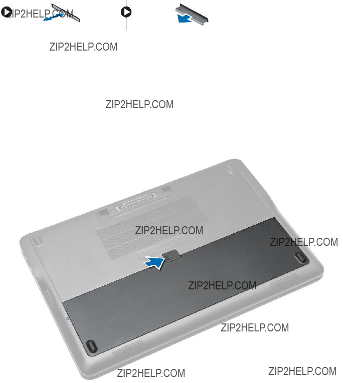
Removing the Battery
1.Follow the procedures in Before Working Inside Your Computer.
2.Slide the release latch to unlock the battery.

3.Lift the battery from the computer.
Installing the Battery
1.Slide the battery into its slot until it clicks into place.
2.Follow the procedures in After Working Inside Your Computer.
Removing the Base Cover
1.Follow the procedures in Before Working Inside Your Computer.
2.Remove battery.
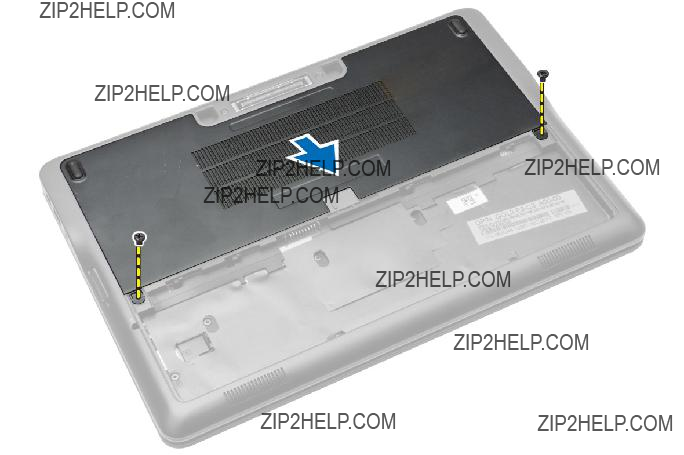
3.Remove the screws that secure the base cover to the computer.

4.Lift the base cover to remove it from the computer.
Installing the Base Cover
1.Place the base cover to align with the screw holes correctly on the computer.
2.Tighten the screws to secure the base cover to the computer.
3.Install battery.
4.Follow the procedures in After Working Inside Your Computer.
Removing the mSATA SSD Card
1.Follow the procedures in Before Working Inside Your Computer.
2.Remove:
a.battery
b.SD card
c.base cover
3.Remove the screw that secures the mSATA SSD card and remove the mSATA SSD card from the computer.

Installing the mSATA SSD Card
1.Place the mSATA SSD card in its slot in the computer.
2.Tighten the screw to secure the mSATA SSD card to the computer.
3.Install:
a.base cover
b.SD card
c.battery
4.Follow the procedures in After Working Inside Your Computer.
Removing the Keyboard Trim
1.Follow the procedures in Before Working Inside Your Computer.
2.Remove battery.
3.Using a plastic scribe, pry the keyboard trim to release it from the computer. Lift up to remove the keyboard trim from the computer.
Installing the Keyboard Trim
1.Align the keyboard trim to its slot.
2.Press along the sides of the keyboard trim until it clicks in place.
3.Install battery.
4.Follow the procedures in After Working Inside Your Computer.
Removing the Keyboard
1.Follow the procedures in Before Working Inside Your Computer.
2.Remove:
a.battery
b.base cover
c.keyboard trim
3.Lift the battery bay and remove the screw that secures the keyboard to the computer.
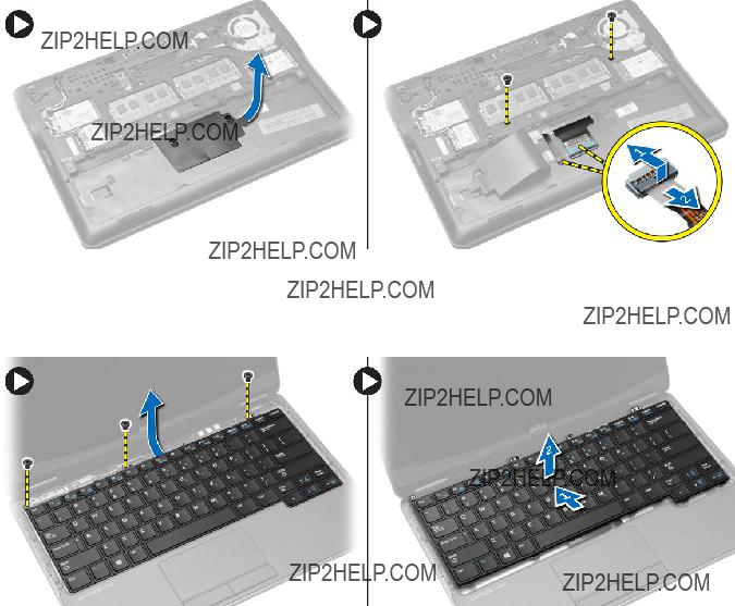
4.Perform the following steps as shown in the illustration:
a.Lift the latch that secure the keyboard cable to the computer [1].
b.Disconnect the keyboard cable the computer [2].
5.Flip the computer and remove the screws that secure the keyboard to the computer.
6.Perform the following steps as shown in the illustration:
a.Slide the keyboard from the computer [1].
b.Lift the keyboard from the computer [2].
Installing the Keyboard
1.Connect the keyboard cable and tighten the screw that secures the keyboard to the computer.
2.Slide the keyboard into its compartment and ensure that it clicks into place.
3.Flip the computer, place the keyboard, and tighten the screws that secure the keyboard to the computer.
4.Install:
a.keyboard trim
b.base cover
c.battery
5.Follow the procedures in After Working Inside Your Computer.
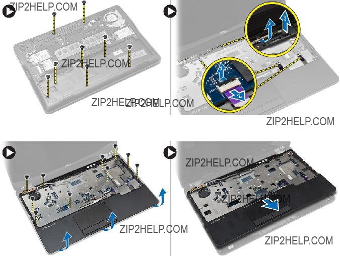
Removing the Palmrest
1.Follow the procedures in Before Working Inside Your Computer.
2.Remove:
a.SD card
b.battery
c.base cover
d.keyboard trim
e.keyboard
3.Remove the screws that secure the palmrest assembly and flip the computer.
4.Perform the following steps as shown in the illustration:
a.Disconnect the cable from the computer.
b.Lift the latch that secures the keyboard cable to the computer [1].
c.Disconnect the keyboard cable [2].
d.Disconnect the touch cable from the computer [3].
e.Unroute the cables from the slot [4].
5.Remove the screws that secure the palmrest assembly to the front of the computer. Pry the edges and lift the palmrest assembly from the computer.

Installing the Palmrest
1.Align the palm rest assembly to its original position in the computer and snap it into place.
2.Tighten the screws to secure the palmrest assembly to the front of the computer.
3.Route the touch cable and connect to the system board.
4.Tighten the screws that secure the palmrest assembly to the base of the computer.
5.Install:
a.keyboard
b.keyboard trim
c.base cover
d.battery
e.SD card
6.Follow the procedures in After Working Inside Your Computer.
Removing the Wi???Fi Switch Board
1.Follow the procedures in Before Working Inside Your Computer.
2.Remove:
a.SD card
b.battery
c.base cover
d.keyboard trim
e.keyboard
f.palmrest
3.Disconnect the
Installing the Wi???Fi Switch Board
1.Insert the
2.Connect the
3.Tighten the screw that secures the
4.Install:
a.palmrest
b.keyboard
c.keyboard trim
d.base cover
e.battery
f.SD card
5.Follow the procedures in After Working Inside Your Computer.
Removing the Memory Module
1.Follow the procedures in Before Working Inside Your Computer.
2.Remove:
a.battery
b.base cover
3.Pry the securing clips away from the memory module until it pops up. Remove the memory module from its connector on the system board.
Installing the Memory Module
1.Insert the memory module into the socket.
2.Press the retention clips to secure the memory module to the system board.
3.Install:
a.base cover
b.battery
4.Follow the procedures in After Working Inside Your Computer.
Removing the WLAN Card
1.Follow the procedures in Before Working Inside Your Computer.
2.Remove:
a.battery
b.base cover
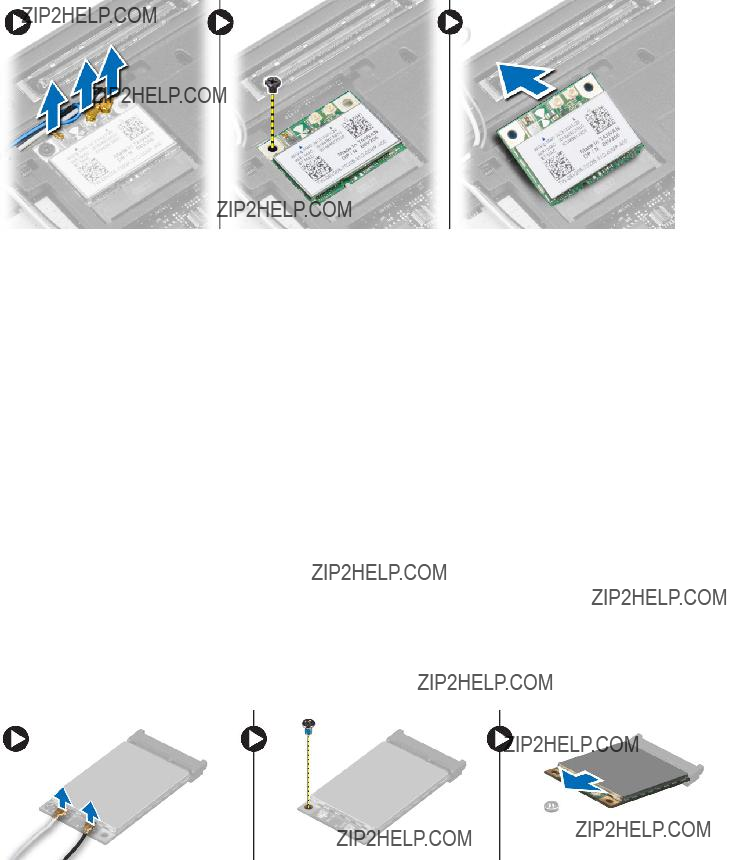
3.Disconnect the antenna cables from the WLAN card and remove the screw that secures the WLAN card to the computer. Remove the WLAN card from the computer.
Installing the WLAN Card
1.Insert the WLAN card into its connector at a
2.Tighten the screw to secure the WLAN card to the computer.
3.Connect the antenna cables to their respective connectors marked on the WLAN card.
4.Install:
a.base cover
b.battery
5.Follow the procedures in After Working Inside Your Computer.
Removing the WWAN Card
1.Follow the procedures in Before Working Inside Your Computer.
2.Remove:
a.battery
b.SD card
c.base cover
3.Disconnect the antenna cables from the WWAN card.
4.Remove the screw that secures the WWAN card to the computer.
5.Disconnect the antenna cables from the WWAN card. Remove the screw that secures the WWAN card to the computer and remove it.

Installing the WWAN Card
1.Place the WWAN card in its slot in the system board.
2.Press the WWAN card down and tighten the screw to secure the WWAN card to the computer.
3.Connect the antenna cables to their respective connectors marked on the WWAN card.
4.Install:
a.base cover
b.SD card
c.battery
5.Follow the procedures in After Working Inside Your Computer.
Removing the Display Bezel
1.Follow the procedures in Before Working Inside Your Computer.
2.Remove the battery.
3.Pry the edges of the display bezel. Remove the display bezel from the display assembly.
Installing the Display Bezel
1.Align the display bezel in place and snap it in place.
2.Align the hinge covers on display assembly and snap it in place.
3.Install the battery
4.Follow the procedures in After Working Inside Your Computer.
Removing the Display Panel
1.Follow the procedures in Before Working Inside Your Computer.
2.Remove:
a.battery
b.display bezel
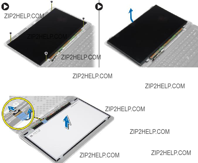
3.Remove the screws that secure the display panel to the display assembly. Lift the display panel over.
4.Perform the following steps as shown in the illustration:
a.Peel the LVDS cable connector tape [1].
b.Disconnect the LVDS cable from the display panel [2].
c.Remove the display panel from the display assembly [3].
Installing the Display Panel
1.Connect the display cable (LVDS cable) to its connector on the display panel.
2.Place the display panel to its original position on the display assembly.
3.Tighten the screws to secure the display panel to the display assembly.
4.Install:
a.display bezel
b.battery
5.Follow the procedures in After Working Inside Your Computer.

Removing the
1.Follow the procedures in Before Working Inside Your Computer.
2.Remove:
a.SD card
b.battery
c.base cover
d.keyboard trim
e.keyboard
f.palmrest
3.Remove the screw that secures the
4.Perform the following steps as shown in the illustration:
a.Lift the latch that secures I/O cable to the computer [1].
b.Disconnect the I/O cable from the system board [2].
5.Disconnect the
Installing the
1.Place the
2.Route the cables and connect the
3.Connect the I/O cable to the system board.
4.Tighten the screw that secures the
5.Install:
a.palmrest
b.keyboard
c.keyboard trim
d.base cover
e.battery
f.SD card
6.Follow the procedures in After Working Inside Your Computer.

Removing the Speakers
1.Follow the procedures in Before Working Inside Your Computer.
2.Remove:
a.SD card
b.battery
c.base cover
d.keyboard trim
e.keyboard
f.palmrest
3.Perform the following steps as shown in the illustration:
a.Disconnect the speaker cable [1].
b.Remove the screws that secure the speakers to the computer.
c.Unroute the speaker cable from the system board [2].
d.Remove the speakers from the computer.
Installing the Speakers
1.Align the speakers to their original position and tighten the screws to secure the speakers to the computer.
2.Route the speaker cable on the computer and connect it to the system board.
3.Install:
a.palmrest
b.keyboard
c.keyboard trim
d.base cover
e.battery
f.SD card
4.Follow the procedures in After Working Inside Your Computer.
Removing the
1.Follow the procedures in Before Working Inside Your Computer.
2.Remove battery.

3.Remove the screws that secure the
Installing the
1.Place the
2.Install battery.
3.Follow the procedures in After Working Inside Your Computer.
Removing the Heatsink
1.Follow the procedures in Before Working Inside Your Computer.
2.Remove:
a.SD card
b.battery
c.base cover
d.mSATA
e.keyboard trim
f.keyboard
g.palmrest
h.
i.display assembly
3.Remove the screws that secure the heatsink to the computer.

4.Perform the following steps as shown in the illustration:
a.Lift the heatsink from the computer [1].
b.Remove the heatsink from the computer [2].
Installing the Heatsink
1.Place the heatsink into its original position on the computer.
2.Tighten the screws to secure the heatsink to the computer.
3.Install:
a.display assembly
b.
c.palmrest
d.keyboard
e.keyboard trim
f.mSATA
g.base cover
h.battery
i.SD card
4.Follow the procedures in After Working Inside Your Computer.
Removing the Display Assembly
1.Follow the procedures in Before Working Inside Your Computer.
2.Remove:
a.battery
b.SD card
c.base cover
d.keyboard
e.palmrest

3.Perform the following steps as shown in the illustration:
a.Disconnect the WLAN cable from the system board [1].
b.Unroute the WLAN cables from the slot [2].
c.Remove the screw that secures the heatsink to the computer.
4.Perform the following steps as shown in the illustration: Disconnect the antenna cables from the wireless solution.
a.Disconnect the LVDS cable from the system board [1].
b.Unroute the cable from the slot [2].
c.Remove the screws and pull the antenna cables from the holes on the base chassis that secure the display assembly to the computer.
5.Remove the screws that secure the display assembly to the computer and lift the display assembly from the computer.

Installing the Display Assembly
1.Insert the LVDS and wireless antenna cables through the holes on the base chassis and connect them.
2.Place the display assembly onto the computer.
3.Tighten the screws on both sides to secure the display assembly.
4.Tighten the screw that secures heatsink to the computer.
5.Route and connect the LVDS cables through the routing channel.
6.Connect the WLAN cable to the computer.
7.Install:
a.palmrest
b.keyboard
c.base cover
d.SD card
e.battery
8.Follow the procedures in After Working Inside Your Computer.
Removing the System Fan
1.Follow the procedures in Before Working Inside Your Computer.
2.Remove:
a.battery
b.SD card
c.base cover
d.keyboard trim
e.keyboard
f.palmrest
g.
3.Remove the screws that secure the system fan to the computer and lift the system fan. Disconnect the system fan cable and lift the fan from the computer.
Installing the System Fan
1.Connect the
2.Tighten the screws that secure the system fan to the computer.
3.Align the system fan in its place on the system board.
4.Install:
a.
b.palmrest
c.keyboard
d.keyboard trim
e.base cover
f.SD card
g.battery
5.Follow the procedures in After Working Inside Your Computer.
Removing the System Board
1.Follow the procedures in Before Working Inside Your Computer.
2.Remove:
a.SD card
b.battery
c.base cover
d.mSATA
e.keyboard trim
f.keyboard
g.palmrest
h.speaker
i.
j.display assembly
k.system fan
l.heat sink
m.I/O cable

3.Perform the following steps as shown in the illustration:
a.Lift the I/O latch [1].
b.Remove the I/O cable from the system board [2].
c.Disconnect the I/O cable from system board[3].
d.Disconnect the speaker cable from the system board.
e.Remove the screws that secure the system board to the computer.
4.Perform the following steps as shown in the illustration:
a.Lift the left edge of system board partially to a
b.Remove the system board from the computer [2].
Installing the System Board
1.Align the system board in its place on the computer.
2.Tighten the screws to secure the system board.
3.Connect the following cables to the system board:
a.speaker
b.I/O cable

4.Install:
a.system fan
b.heat sink
c.display assembly
d.
e.speaker
f.palmrest
g.keyboard
h.keyboard trim
i.mSATA
j.base cover
k.battery
l.SD card
5.Follow the procedures in After Working Inside Your Computer.
Removing the Power Connector
1.Follow the procedures in Before Working Inside Your Computer.
2.Remove:
a.SD card
b.battery
c.base cover
d.keyboard
e.palmrest
f.system fan
3.Disconnect the
Installing the Power Connector
1.Insert the power connector in its slot.
2.Connect the power connector to the system board.
3.Tighten the screw that secures the power connector to the system board.
4.Install:
a.system fan
b.palmrest
c.keyboard
d.base cover
e.battery
f.SD card
5.Follow the procedures in After Working Inside Your Computer.

4
Docking Port Information
The docking port is used for connecting the laptop to a docking station (optional).
1.Docking Port

5
System Setup
Boot Sequence
Boot Sequence allows you to bypass the System Setup???defined boot device order and boot directly to a specific device (for example: optical drive or hard drive). During the
???Access System Setup by pressing <F2> key
???Bring up the
The
???Removable Drive (if available)
???STXXXX Drive
 NOTE: XXX denotes the SATA drive number.
???Optical Drive
???Diagnostics
 NOTE: Choosing Diagnostics, will display the ePSA diagnostics screen.
The boot sequence screen also displays the option to access the System Setup screen.
Navigation Keys
The following table displays the system setup navigation keys.
NOTE: For most of the system setup options, changes that you make are recorded but do not take effect until you
Table 1. Navigation Keys

System Setup Options
NOTE: Depending on your computer and its installed devices, the items listed in this section may or may not appear.
Table 2. General


Default Setting: Not set
Internal
???Enter the old password
???Enter the new password
???Confirm the new password
Default Setting: Not set


NOTE: For enable system needs to be UEFI boot mode and enable legacy option ROMs to be turned off.


Extended BIOS POST Time Allows to creates an additional
???0 seconds
???5 seconds
???10 seconds
Table 10. Virtualization Support

Table 11. Wireless
Updating the BIOS
It is recommended to update your BIOS (system setup), on replacing the system board or if an update is available. For laptops, ensure that your computer battery is fully charged and connected to a power outlet
1.
2.Go to dell.com/support.

3.Enter the Service Tag or Express Service Code and click Submit.
 NOTE: To locate the Service Tag, click Where is my Service Tag?
NOTE: If you cannot find your Service Tag, click Detect My Product. Proceed with the instructions on screen.
4.If you are unable to locate or find the Service Tag, click the Product Category of your computer.
5.Choose the Product Type from the list.
6.Select your computer model and the Product Support page of your computer appears.
7.Click Get drivers and click View All Drivers. The Drivers and Downloads page opens.
8.On the Drivers and Downloads screen, under the Operating System
9.Identify the latest BIOS file and click Download File.
You can also analyze which drivers need an update. To do this for your product, click Analyze System for Updates and follow the instructions on the screen.
10.Select your preferred download method in the Please select your download method below window; click Download File.
The File Download window appears.
11.Click Save to save the file on your computer.
12.Click Run to install the updated BIOS settings on your computer. Follow the instructions on the screen.
System and Setup Password
You can create a system password and a setup password to secure your computer.
System password Password that you must enter to log on to your system.
Setup password Password that you must enter to access and make changes to the BIOS settings of your computer.
CAUTION: The password features provide a basic level of security for the data on your computer.
CAUTION: Anyone can access the data stored on your computer if it is not locked and left unattended.
NOTE: Your computer is shipped with the system and setup password feature disabled.
Assigning a System Password and Setup Password
You can assign a new System Password and/or Setup Password or change an existing System Password and/or Setup Password only when Password Status is Unlocked. If the Password Status is Locked, you cannot change the System Password.
NOTE: If the password jumper is disabled, the existing System Password and Setup Password is deleted and you need not provide the system password to log on to the computer.

To enter a system setup, press <F2> immediately after a
1.In the System BIOS or System Setup screen, select System Security and press <Enter>. The System Security screen appears.
2.In the System Security screen, verify that Password Status is Unlocked.
3.Select System Password , enter your system password, and press <Enter> or <Tab>. Use the following guidelines to assign the system password:
???A password can have up to 32 characters.
???The password can contain the numbers 0 through 9.
???Only lower case letters are valid, upper case letters are not allowed.
???Only the following special characters are allowed: space, (???), (+), (,),
4.Type the system password that you entered earlier and click OK.
5.Select Setup Password, type your system password and press <Enter> or <Tab>. A message prompts you to
6.Type the setup password that you entered earlier and click OK.
7.Press <Esc> and a message prompts you to save the changes.
8.Press <Y> to save the changes. The computer reboots.
Deleting or Changing an Existing System and/or Setup Password
Ensure that the Password Status is Unlocked (in the System Setup) before attempting to delete or change the existing System and/or Setup password. You cannot delete or change an existing System or Setup password, if the Password Status is Locked.
To enter the System Setup, press <F2> immediately after a
1.In the System BIOS or System Setup screen, select System Security and press <Enter>. The System Security screen is displayed.
2.In the System Security screen, verify that Password Status is Unlocked.
3.Select System Password, alter or delete the existing system password and press <Enter> or <Tab>.
4.Select Setup Password, alter or delete the existing setup password and press <Enter> or <Tab>.
NOTE: If you change the System and/or Setup password,
5.Press <Esc> and a message prompts you to save the changes.
6.Press <Y> to save the changes and exit from the System Setup. The computer reboots.
6
Diagnostics
If you experience a problem with your computer, run the ePSA diagnostics before contacting Dell for technical assistance. The purpose of running diagnostics is to test your computer's hardware without requiring additional equipment or risking data loss. If you are unable to fix the problem yourself, service and support personnel can use the diagnostics results to help you solve the problem.
Enhanced
Diagnostics
The ePSA diagnostics (also known as system diagnostics) performs a complete check of your hardware. The ePSA is embedded with the BIOS and is launched by the BIOS internally. The embedded system diagnostics provides a set of options for particular devices or device groups allowing you to:
???Run tests automatically or in an interactive mode
???Repeat tests
???Display or save test results
???Run thorough tests to introduce additional test options to provide extra information about the failed device(s)
???View status messages that inform you if tests are completed successfully
???View error messages that inform you of problems encountered during testing
CAUTION: Use the system diagnostics to test only your computer. Using this program with other computers may cause invalid results or error messages.
NOTE: Some tests for specific devices require user interaction. Always ensure that you are present at the computer terminal when the diagnostic tests are performed.
1.
2.As the computer boots, press the <F12> key as the Dell logo appears.
3.On the boot menu screen, select the Diagnostics option.
The Enhanced
4.If you wish to run a diagnostic test on a specific device, press <Esc> and click Yes to stop the diagnostic test.
5.Select the device from the left pane and click Run Tests.
6.If there are any issues, error codes are displayed. Note the error code and contact Dell.

Device Status Lights
Table 14. Device Status Lights
Turns on when you turn on the computer and blinks when the computer is in a power management mode.
Turns on when the computer reads or writes data.
Turns on steadily or blinks to indicate battery charge status.
Turns on when wireless networking is enabled.
The device status LEDs are usually located either on the top or left side of the keyboard. They are used to display the storage, battery and wireless devices connectivity and activity. Apart from that they can be useful as a diagnostic tool when there's a possible failure to the system.
The following table lists how to read the LED codes when possible errors occur.
Table 15. LED Lights
Battery Status Lights
If the computer is connected to an electrical outlet, the battery light operates as follows:

7
Specifications
NOTE: Offerings may vary by region. The following specifications are only those required by law to ship with your computer. For comprehensive specification of your computer go to Specifications??? section in your Owner???s Manual available on the support site at dell.com/support. For more information about the configuration of your computer, go to Help and Support in your Windows operating system and select the option to view information about your computer.
Table 16. System Information


Table 23. Ports and Connectors

Table 26. Touchpad

Table 29. Physical
8
Contacting Dell
NOTE: If you do not have an active Internet connection, you can find contact information on your purchase invoice, packing slip, bill, or Dell product catalog.
Dell provides several online and
1.Go to dell.com/contactdell.
2.Verify your country or region from the
3.Select your support category: Technical Support, Customer Support, Sales, or International Support Services.
4.Select the appropriate service or support link based on your requirement.
NOTE: If you have purchased a Dell system, you may be asked for the Service Tag.