Dell??? PowerEdge??? C2100
Systems
Hardware Owner???s
Manual
Regulatory Model
Dell??? PowerEdge??? C2100
Systems
Hardware Owner???s
Manual
Regulatory Model
Notes, Cautions, and Warnings
NOTE: A NOTE indicates important information that helps you make better use of your computer.
CAUTION: A CAUTION indicates potential damage to hardware or loss of data if instructions are not followed.
WARNING: A WARNING indicates a potential for property damage, personal injury, or death.
____________________
Information in this document is subject to change without notice. ?? 2010 Dell Inc. All rights reserved.
Reproduction of these materials in any manner whatsoever without the written permission of Dell Inc. is strictly forbidden.
Trademarks used in this text: Dell, the DELL logo, and PowerEdge are trademarks of Dell Inc.; Intel and SpeedStep are registered trademarks of Intel Corporation in the U.S. and other countries; Microsoft and Windows are either trademarks or registered trademarks of Microsoft Corporation in the United States and/or other countries.
Other trademarks and trade names may be used in this document to refer to either the entities claiming the marks and names or their products. Dell Inc. disclaims any proprietary interest in trademarks and trade names other than its own.
Regulatory Model

Contents
Contents 3

4 Contents

Contents 5

6 Contents

8 Contents

About Your System
Accessing System Features During Startup
The following keystrokes provide access to system features during startup.
Figure
1
4
5
one of these buttons is pushed, the LCD panel on the front and the blue system status indicator on the back blink until one of the buttons is pushed again.

NOTE: When powering on the system, the video monitor can take from several seconds to over 2 minutes to display an image, depending on the amount of memory installed in the system.
NOTE: On
NOTE: To force an ungraceful shutdown, press and hold the power button for
5 seconds.
Figure
 1
1

Table
Figure
NIC Indicator Codes
Figure
1

Table

Power and System Board Status Codes
The LEDs on the system front and back panel display status codes during system startup. All systems share the same LEDs on the front and back panel. Table
Table
Collecting System Event Log for Investigation
If the front panel LED blinks for 30 to 60 seconds upon applying AC power to the power supply, the baseboard management controller (iBMC) is initializing. If not, then the iBMC is not functioning. If the iBMC is working, try to gather system event log (SEL) information for investigation.
POST Error Codes

Remove AC power to the system for 10 seconds and restart the system.
If the problem persists, see "Getting Help" on page 131.
Remove AC power to the system for 10 seconds and restart the system.
If the problem persists, see "Getting Help" on page 131.
Remove AC power to the system for 10 seconds and restart the system.
If the problem persists, see "Getting Help" on page 131.
Remove AC power to the system for 10 seconds and restart the system.
If the problem persists, see "Getting Help" on page 131.
device available


DISABLED
Error
Remove AC power to the system for 10 seconds and restart the system.
If the problem persists, see "Getting Help" on page 131.
Remove AC power to the system for 10 seconds and restart the system.
If the problem persists, see "Getting Help" on page 131.
Remove AC power to the system for 10 seconds and restart the system.
If the problem persists, see "Getting Help" on page 131.
See "Troubleshooting System Memory" on page 115.
If the problem persists, see "Getting Help" on page 131.


installed processor. The processor will be run at a reduced frequency, which will impact system performance.
Bus ratio or
VID configuration has failed! Please enter BIOS Setup and
The message is displayed on the screen, an error is logged to the SEL, and user input is required to continue. The user can take immediate corrective action or choose to continue booting.
Ensure that the processor heat sinks are properly installed.
See "Troubleshooting Processors" on page 120 and "Troubleshooting System Cooling Problems" on page 114.

detected by
PROCHOT#
Ensure that the processor heat sinks are properly installed.
See "Troubleshooting Processors" on page 120 and "Troubleshooting System Cooling Problems" on page 114.
Ensure that the processor heat sinks are properly installed.
See "Troubleshooting Processors" on page 120 and "Troubleshooting System Cooling Problems" on page 114.
detected by
PROCHOT#
Ensure that the processor heat sinks are properly installed.
See "Troubleshooting Processors" on page 120 and "Troubleshooting System Cooling Problems" on page 114.
detected by
PROCHOT#
Ensure that the processor heat sinks are properly installed.
See "Troubleshooting Processors" on page 120 and "Troubleshooting System Cooling Problems" on page 114.
Ensure that the processor heat sinks are properly installed.
See "Troubleshooting Processors" on page 120 and "Troubleshooting System Cooling Problems" on page 114.
detected by
PROCHOT#
Ensure that the processor heat sinks are properly installed.
See "Troubleshooting Processors" on page 120 and "Troubleshooting System Cooling Problems" on page 114.

system???s Getting Started Guide.
Ensure that your processors match and conform to the type described in the processor technical specifications outlined in your system???s Getting Started Guide.
Ensure that your processors match and conform to the type described in the processor technical specifications outlined in your system???s Getting Started Guide.
current stepping
Ensure that your processors match and conform to the type described in the processor technical specifications outlined in your system???s Getting Started Guide.
Ensure that your processors match and conform to the type described in the processor technical specifications outlined in your system???s Getting Started Guide.
current stepping
Ensure that your processors match and conform to the type described in the processor technical specifications outlined in your system???s Getting Started Guide.
system???s Getting Started Guide.
Remove AC power to the system for 10 seconds and restart the system.
If the problem persists, see "Getting Help" on page 131.
Ensure that your processors match and conform to the type described in the processor technical specifications outlined in your system???s Getting Started Guide.
Ensure that your processors match and conform to the type described in the processor technical specifications outlined in your system???s Getting Started Guide.
Reset password. See "Jumper Settings" on page 123.
If the problem persists, see "Getting Help" on page 131.
Controller not found at the specified address!!!
See "Troubleshooting a USB Device" on page 108.
If the problem persists, see "Getting Help" on page 131.
See "Troubleshooting a USB Device" on page 108.
If the problem persists, see "Getting Help" on page 131.
UBS device found and disabled!!!
See "Troubleshooting a USB Device" on page 108.
If the problem persists, see "Getting Help" on page 131.

not supported by this USB Host Controller!!!
See "Troubleshooting a USB Device" on page 108.
If the problem persists, see "Getting Help" on page 131.
disabled. It requires 64- bit data support in the BIOS.
See "Troubleshooting a USB Device" on page 108.
If the problem persists, see "Getting Help" on page 131.
Runtime area! SMBIOS data will not be available.
See "Troubleshooting System Memory" on page 115.
If the problem persists, see "Getting Help" on page 131.
SMBIOS data will not be available.
See "Troubleshooting System Memory" on page 115.
If the problem persists, see "Getting Help" on page 131.
Remove AC power to the system for 10 seconds and restart the system.
If the problem persists, see "Getting Help" on page 131.

System may operate in PCI or Non- MPS mode.
Remove AC power to the system for 10 seconds and restart the system.
If the problem persists, see "Getting Help" on page 131.

Beep Codes
The following table describes the system pre post beep codes.
Table
Post Beep Codes
Table

Other Information You May Need
WARNING: See the safety and regulatory information that shipped with your system. Warranty information may be included within this document or as a separate document.
???The Getting Started Guide provides an overview of rack installation, system features, setting up your system, and technical specifications.
???Dell systems management application documentation provides information about installing and using the systems management software. This document is available online at support.dell.com/manuals.
NOTE: Always check for updates on support.dell.com/manuals and read the updates first because they often supersede information in other documents.

Using the System Setup Program
Start Menu
The system employs the latest AMI Core BIOS, which is stored in
Flash memory. The Flash memory supports the Plug and Play specification, and contains a System Setup program, the
This system board supports system BIOS shadowing, enabling the BIOS to execute from
The system board helps to configure the following items:
???Hard drives, diskette drives, and peripherals
???Password protection from unauthorized use
???Power management features
This Setup utility should be executed under the following conditions:
???When changing the system configuration
???When a configuration error is detected by the system and you are prompted to make changes to the Setup utility
???When redefining the communication ports to prevent any conflicts
???When changing the password or making other changes to the security setup
NOTE: Only items in brackets [ ] can be modified. Items that are not in brackets are display only.
System Setup Options at Boot
You can initiate Setup by pressing <F2> during POST.
Console Redirection
The console redirection allows a remote user to diagnose and fix problems on a system, which has not successfully booted the operating system.
The centerpiece of the console redirection is the BIOS Console. The BIOS Console is a Flash
The BIOS supports console redirection to a serial port. If a serial port based headless system support is provided by the system, the system must provide support for redirection of all BIOS driven console I/O to the serial port.
The driver for the serial console must be capable of supporting the functionality documented in the ANSI Terminal Definition.

Main Menu
The main menu displays information about your system board and BIOS.
Main Screen
Figure
Use [ENTER],[TAB] or [SHIFT TAB] to select
Use [+] or
Select Screen
Select Item
+- Change Field
Tab Select Field
F1 General Help
F10 Save and Exit
Esc Exit
NOTE: The options for the System Setup program change based on the system configuration.
NOTE: The System Setup program defaults are listed under their respective options in the following sections, where applicable.

AMIBIOS Settings
Processor Settings
System Memory Settings
Advanced Menu
This option displays a table of items that define advanced information about your system.
WARNING: Making incorrect settings to items on these pages may cause the system to malfunction. Unless you have the experience in adjusting these items, it is recommended that you leave these settings at the default values. If making settings to items on these pages causes your system to malfunction or prevents the system from booting, open BIOS and choose "Load Optimal Defaults" in the Exit menu to boot up normally.
Processor Configuration
Memory Configuration
IDE Configuration
Super IO Configuration
USB Configuration
PCI Configuration


Boot Menu
Boot Settings Configuration


Server Menu
NOTE: Delay Time, Minimum time, and Maximum time are only shown in SETUP screen when AC Power Recovery Delay is set to User define. The selection of Restore on AC Power Loss setup to
NMI on Error (Fatal default)
Enable to set the state of NMI on Error:
???Fatal: Fatal error issue NMI.
???Uncorrectable: Fatal and Uncorrectable errors issue NMI.
???Correctable: Issues NMI on all errors.
iBMC LAN Configuration

Remote Access Configuration
NOTE: When Flow Control is set to Software, the Hyper Terminal on remote side is discontinued by pressing <Ctrl><S>. But the <Ctrl><S> is also the Setup Key Stroke for setting onboard NIC PXE Option ROM Configuration. Therefore, we suggest users change <Ctrl><S> to <Ctrl><B> in PXE OPROM Configuration in order to avoid that the Hyper Terminal on remote side is discontinued when pressing <Ctrl><S>.
Security Menu
Supervisor Password Displays whether the supervisor password is installed or not.
Clear User Password Select to clear the user password.
Installing System Components
Safety Instructions
WARNING: Working on systems that are still connected to a power supply can be extremely dangerous.
CAUTION: System components and electronic circuit boards can be damaged by discharge of static electricity.
CAUTION: Many repairs may only be done by a certified service technician. You should only perform troubleshooting and simple repairs as authorized in your product documentation, or as directed by the online or telephone service and support team. Damage due to servicing that is not authorized by Dell is not covered by your warranty. Read and follow the safety instructions that came with the product.
To avoid injury to yourself or damage to your system, follow these guidelines:
???Always disconnect the system from the power outlet whenever you are working inside the system case.
???If possible, wear a grounded wrist strap when you are working inside
the system case. Alternatively, discharge any static electricity by touching the bare metal chassis of the system case, or the bare metal body of any other grounded appliance.
???Hold electronic circuit boards by the edges only. Do not touch the components on the board unless it is necessary to do so. Do not flex or stress the circuit board.
???Leave all components inside the
Recommended Tools
???Phillips screwdriver
???
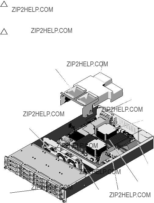
Inside the System
CAUTION: Many repairs may only be done by a certified service technician. You should only perform troubleshooting and simple repairs as authorized in your product documentation, or as directed by the online or telephone service and support team. Damage due to servicing that is not authorized by Dell is not covered by your warranty. Read and follow the safety instructions that came with the product.
CAUTION: This system must be operated with the system cover installed to ensure proper cooling.
Figure
1
11
10
2
9
 3
3
4
5

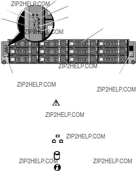
Hard Drives
CAUTION: Many repairs may only be done by a certified service technician. You should only perform troubleshooting and simple repairs as authorized in your product documentation, or as directed by the online or telephone service and support team. Damage due to servicing that is not authorized by Dell is not covered by your warranty. Read and follow the safety instructions that came with the product.
CAUTION: Use only hard drives that have been tested and approved for use with the SAS/SATA backplane.
CAUTION: When you remove or install the hard drive, take note of the drive carrier orientation before sliding it out. The carrier does not fit back into the bay if inserted incorrectly. Make sure that the hard drive is connected to the hard drive connector on the backplane
CAUTION: When installing a
CAUTION: To prevent data loss, ensure that your operating system supports
CAUTION: Combining SATA and SAS hard drives in the same system configuration is not supported.
Your system supports up to twelve 3.5" hard drives and two optional internal 2.5" hard drives.

Removing a
CAUTION: To maintain proper system cooling, all empty
Press the release button and slide the
Figure
2
1
Installing a
Align the
Removing a
1From the RAID management software, prepare the drive for removal.Wait until the
If the drive has been online, the green activity/fault indicator will flash as the drive is powered down. When the drive indicators are off, the drive is ready for removal. See

2Press the release button on the front of the
3Using the release lever, slide the
4If you are not installing another
Figure
1
4
 2
2
Installing a
1Press the release button on the front of the
2With the release lever on the
3Close the release lever to lock the

Removing a Hard Drive From a
1Turn over the hard drive and remove the four screws on the
2Lift the hard drive out of the
Figure
1 
 2
2
Installing a Hard Drive Into a
1Insert the hard drive into the
2Align the slots on the hard drive with the slots on the
3Attach the four screws to secure the hard drive to the

Removing the Optional Internal Hard Drive
1Turn off the system, including any attached peripherals, and disconnect the system from its electrical outlet.
2Open the system. See "Opening the System" on page 58.
3Remove the cooling shroud. See "Removing the Cooling Shroud" on page 60.
4Remove the eight screws that secure the internal hard drives to the hard- drive assembly. See Figure
5Remove the internal hard drives.
Figure
1
2
 3
3
4

Installing the Optional Internal Hard Drive
1Place the hard drives in position on the hard drive assembly.
2Affix the eight screws securing the hard drives to the
3Replace the cooling shroud. See "Installing the Cooling Shroud" on page 61.
4Close the system. See "Closing the System" on page 59.
5Reconnect the system and peripherals to their electrical outlets and turn on the system.
Opening and Closing the System
WARNING: Whenever you need to lift the system, get others to assist you. To avoid injury, do not attempt to lift the system by yourself.
CAUTION: Many repairs may only be done by a certified service technician. You should only perform troubleshooting and simple repairs as authorized in your product documentation, or as directed by the online or telephone service and support team. Damage due to servicing that is not authorized by Dell is not covered by your warranty. Read and follow the safety instructions that came with the product.
Opening the System
1Turn off the system, including any attached peripherals, and disconnect the system from its electrical outlet.
2Remove the securing screw on the top of the system. See Figure
3Press down the locking button and with your palms on the traction pad, slide and lift the cover away from the system.

Figure
 3
3
4
Closing the System
1Place the cover on the chassis and offset it slightly toward the back of the system, so that the hooks on the sides of the cover fit over the corresponding slots on the sides of the chassis.
2Slide the cover toward the front of the chassis till the screw hole on the cover is aligned with the hole on the chassis.
3Secure the cover with the securing screw. See Figure
4Reconnect the system and peripherals to their electrical outlets and turn on the system.

Cooling Shroud
CAUTION: Many repairs may only be done by a certified service technician. You should only perform troubleshooting and simple repairs as authorized in your product documentation, or as directed by the online or telephone service and support team. Damage due to servicing that is not authorized by Dell is not covered by your warranty. Read and follow the safety instructions that came with the product.
Removing the Cooling Shroud
1Turn off the system, including any attached peripherals, and disconnect the system from its electrical outlet.
2Open the system. See "Opening the System" on page 58.
3If applicable, disconnect the internal hard drive cables.
4Remove the four securing screws. See Figure
5Lift the cooling shroud out and away from the chassis. See Figure
Figure
 3
3
Installing the Cooling Shroud
1Align the cooling shroud around the sides of the heat sink and along the memory slots and lower it into the system. See Figure
2Secure the cooling shroud using the four screws. See Figure
3If applicable, connect the internal hard drive cables.
4Close the system. See "Closing the System" on page 59.
5Reconnect the system and peripherals to their electrical outlets and turn on the system.

Heat Sinks
CAUTION: Many repairs may only be done by a certified service technician. You should only perform troubleshooting and simple repairs as authorized in your product documentation, or as directed by the online or telephone service and support team. Damage due to servicing that is not authorized by Dell is not covered by your warranty. Read and follow the safety instructions that came with the product.
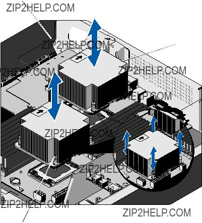
Removing the Heat Sink
1Turn off the system, including any attached peripherals, and disconnect the system from its electrical outlet.
2Open the system. See "Opening the System" on page 58.
3Remove the cooling shroud. See "Removing the Cooling Shroud" on page 60.
4If required, remove the
WARNING: The heat sink is hot to touch for some time after the system has been powered down. Allow the heat sink to cool before handling it.
CAUTION: Never remove the heat sink from a processor unless you intend to remove the processor. The heat sink is necessary to maintain proper thermal conditions.
5Using a #2 Phillips screwdriver, loosen one of the
Wait 30 seconds for the heat sink to loosen from the processor.
6Loosen the screw that is diagonally opposite to the screw that you have already loosened. See Figure
7Repeat step 5 till you have loosened the remaining screws.
8Gently lift the heat sink off the processor and set the heat sink aside with the thermal grease side facing up.
Figure
1
 2
2

Installing the Heat Sink
CAUTION: The heat sinks for CPU0 and CPU1 are different and are labeled accordingly. They must be installed in the correct location and orientation to prevent the system from overheating.
1Using a clean
2Remove the protective cover from the underside of the heat sink.
3Apply new thermal grease evenly to the center of the top of the new processor.
NOTE: Using excess thermal grease can cause grease to contact the processor shield, which can cause contamination of the processor socket.
4Place the heat sink on top of the processor and tighten the four captive screws in the order they were loosened.
5Replace the cooling shroud. See "Installing the Cooling Shroud" on page 61.
6If applicable, replace the
7Close the system. See "Closing the System" on page 59.
8Reconnect the system and peripherals to their electrical outlets, and turn on the system.
Processor
CAUTION: Many repairs may only be done by a certified service technician. You should only perform troubleshooting and simple repairs as authorized in your product documentation, or as directed by the online or telephone service and support team. Damage due to servicing that is not authorized by Dell is not covered by your warranty. Read and follow the safety instructions that came with the product.
Removing the Processor
1Turn off the system, including any attached peripherals, and disconnect the system from its electrical outlet.
2Open the system. See "Opening the System" on page 58.
3Remove the cooling shroud. See "Removing the Cooling Shroud" on page 60.

4 Remove the heat sink. See "Removing the Heat Sink" on page 62.
CAUTION: The processor is held in its socket under strong pressure. Be aware that the release lever can spring up suddenly if not firmly grasped.
5Position your thumb firmly over the processor
6Rotate the lever 90 degrees upward until the processor is released from the socket. See Figure
7Rotate the processor shield upward and out of the way.
CAUTION: Be careful not to bend any of the pins on the ZIF socket when removing the processor. Bending the pins can permanently damage the system board.
8Lift the processor out of the socket and leave the
Figure
1
6
5
 2
2
4
3

Installing the Processor
NOTE: When installing only one processor, the processor must be installed in CPU0 socket (for the socket location, see Figure
NOTE: Your system uses an LGA 1366 socket, which is designed for trouble free insertion of the CPU. After placing the CPU into the socket, press the lever down and lock in place. If you notice any resistance when inserting the CPU, ensure that it is aligned correctly.
NOTE: After removing the processor, place it in an antistatic container for reuse, return, or temporary storage. Do not touch the bottom of the processor. Touch only the side edges of the processor.
NOTE: If you are permanently removing the processor, you must install a processor blank and a
1If you are upgrading your processors, prior to upgrading your system, download and install the latest system BIOS version from support.dell.com. Follow the instructions included in the file and download to install the update on your system.
2Pull the locking lever of the processor socket out and up.
3Unpack the processor if it has not been used previously.
If the processor has already been used, remove any thermal grease from the top of the processor using a
4Locate the pin 1 indicator on the system board socket.
5Locate the pin 1 indicator on the top of the processor. See Figure
6Place the processor over the socket with pin 1 aligned with the pin guide on the processor socket.
CAUTION: Positioning the processor incorrectly can permanently damage the system board or the processor. Be careful not to bend the pins in the ZIF socket.

7Align the notches in the processor with the socket keys on the ZIF socket. See Figure
8With the release lever on the processor socket in the open position, align the processor with the socket keys and set the processor lightly in the socket. See Figure
CAUTION: Do not use force to seat the processor. When the processor is positioned correctly, it engages easily into the socket.
9Close the processor shield.
10Rotate the socket release lever down until it snaps into place. See Figure
11Using a clean
12Open the grease packet included with your processor kit and apply thermal grease evenly to the center of the top of the new processor.
CAUTION: Using excess thermal grease can cause grease to contact the processor shield, which can cause contamination of the processor socket.
13Install the heat sink. See "Installing the Heat Sink" on page 64.
14Replace the cooling shroud. See "Installing the Cooling Shroud" on page 61.
15Close the system. See "Closing the System" on page 59.
16Reconnect the system and peripherals to their electrical outlets, and turn on the system.
17Press <F2> to enter the System Setup program, and check that the processor information matches the new system configuration. See "System Setup Options at Boot" on page 38.
System Memory
Your system supports DDR3 registered DIMMs (RDIMMs).
The system contains 18 memory sockets split into two sets of nine sockets with one set for each processor. Each
The maximum memory that is supported on your system varies according to the types and sizes of memory modules being used:

???
???
General Memory Module Installation Guidelines
To ensure optimal performance of your system, observe the following general guidelines when configuring your system memory.
NOTE: Memory configurations that fail to observe these guidelines can prevent your system from starting and producing any video output.
???Except for memory channels that are unused, all populated memory channels must have identical configurations.
???The memory configuration for each processor must be identical.
???Memory modules of different sizes can be mixed in
???For optimizer mode, memory modules are installed in the numeric order of the sockets beginning with A1 or B1.
???For memory mirroring or advanced ECC mode, the channel furthest from the processor is unused and memory modules are installed beginning with channel A1 or B1 and proceeding with channel A2 or B2.
???Advanced ECC mode requires memory modules that use x4 or x8 DRAM device widths.
???The memory speed of each channel depends on the memory configuration:
???For single- or
???One memory module per channel supports up to 1333 MHz.
???Two memory modules per channel support up to 1066 MHz.
???Three memory modules per channel support up to 800 MHz, regardless of memory module speed.
???For
???One memory module per channel supports up to 1066 MHz.
???Two memory modules per channel are limited to 800 MHz, regardless of the memory module speed.
???If
???If memory modules with different speeds are installed, they operate at the speed of the slowest installed memory module(s).
Three memory channels are allocated to each processor. The number of channels used and the allowable configurations depend on the memory mode selected.
Optimizer (Independent Channel) Mode
In this mode, all three channels are populated with identical memory modules. This mode permits a larger total memory capacity but does not support SDDC with
A minimal
Table
of any configuration.

Supported Memory Configuration
There are eighteen DIMMs on each system board to support processor 0 and processor 1. The DIMM sequence of eighteen DIMM sockets is shown below. When you insert the DIMM(s), you have to always start with DIMM0_CHA. See the following for possible memory configurations.
Table
NOTE: An empty DIMM socket is marked as ???_???. For the best performance, all the DIMMs installed must be of the same speed, capacity, and the DIMMs must be from one manufacturer.
Removing Memory Modules
WARNING: The memory modules are hot to touch for some time after the system has been powered down. Allow time for the memory modules to cool before handling them. Handle the memory modules by the card edges and avoid touching the components on the memory module.
CAUTION: Many repairs may only be done by a certified service technician. You should only perform troubleshooting and simple repairs as authorized in your product documentation, or as directed by the online or telephone service and support team. Damage due to servicing that is not authorized by Dell is not covered by your warranty. Read and follow the safety instructions that came with the product.
1Turn off the system, including any attached peripherals, and disconnect the system from its electrical outlet.
2Open the system. See "Opening the System" on page 58.
3Remove the cooling shroud. See "Removing the Cooling Shroud" on page 60.
4Locate the memory module sockets.
5Press down and out on the ejectors on each end of the socket until the memory module pops out of the socket. See Figure
CAUTION: Handle each memory module only on either card edge, making sure not to touch the middle of the memory module.
6Lift out the memory module.
7Replace the cooling shroud. See "Installing the Cooling Shroud" on page 61.
8Close the system. See "Closing the System" on page 59.
9Reconnect the system to its electrical outlet and turn on the system, including any attached peripherals.

Figure
1
2
3 
3 alignment key
Installing Memory Modules
CAUTION: Many repairs may only be done by a certified service technician. You should only perform troubleshooting and simple repairs as authorized in your product documentation, or as directed by the online or telephone service and support team. Damage due to servicing that is not authorized by Dell is not covered by your warranty. Read and follow the safety instructions that came with the product.
1Locate the memory module sockets. See Figure
2Press the ejectors on the memory module socket down and out, as shown in Figure
Handle each memory module only on either card edge, making sure not to touch the middle of the memory module.
3Align the memory module's edge connector with the alignment key of the memory module socket, and insert the memory module in the socket.

NOTE: The memory module socket has an alignment key that allows you to install the memory module in the socket in only one way.
4Press down on the memory module with your thumbs until the ejectors lock into position. See Figure
When the memory module is properly seated in the socket, the ejectors on the memory module socket align with the ejectors on the other sockets that have memory modules installed.
5Replace the cooling shroud. See "Installing the Cooling Shroud" on page 61.
6Close the system. See "Closing the System" on page 59.
7Reconnect your system and peripherals to their electrical outlets, and turn on the system.
8Start up the system, press <F2> to enter the System Setup program, and check the System Memory settings on the main System Setup screen.
The system should have already changed the value to reflect the newly installed memory.
9If the value is incorrect, one or more of the memory modules may not be installed properly. Repeat step 3 through step 8 of this procedure, checking to ensure that the memory modules are firmly seated in their sockets.
CAUTION: Expansion cards can only be installed in the slots on the
Removing the
CAUTION: Many repairs may only be done by a certified service technician. You should only perform troubleshooting and simple repairs as authorized in your product documentation, or as directed by the online or telephone service and support team. Damage due to servicing that is not authorized by Dell is not covered by your warranty. Read and follow the safety instructions that came with the product.
1Turn off the system, including any attached peripherals, and disconnect the system from its electrical outlet.
2Open the system. See "Opening the System" on page 58.
3Remove the cooling shroud. See "Removing the Cooling Shroud" on page 60.
4Grasp the
5Lift the
6Remove the four securing screws on the

Figure
1
 2
2
Figure
1
 2
2
 3
3
Installing the
CAUTION: Many repairs may only be done by a certified service technician. You should only perform troubleshooting and simple repairs as authorized in your product documentation, or as directed by the online or telephone service and support team. Damage due to servicing that is not authorized by Dell is not covered by your warranty. Read and follow the safety instructions that came with the product.
1Replace the
2Align the
3Seat the
4Replace the cooling shroud. See "Installing the Cooling Shroud" on page 61.

5Replace the system cover. See "Closing the System" on page 59.
6Reconnect the system and peripherals to their electrical outlets, and turn on the system.
Removing the Expansion Card
CAUTION: Many repairs may only be done by a certified service technician. You should only perform troubleshooting and simple repairs as authorized in your product documentation, or as directed by the online or telephone service and support team. Damage due to servicing that is not authorized by Dell is not covered by your warranty. Read and follow the safety instructions that came with the product.
1Turn off the system, including any attached peripherals, and disconnect the system from its electrical outlet.
2Open the system. See "Opening the System" on page 58.
3Remove the cooling shroud. See "Removing the Cooling Shroud" on page 60.
4Remove the
5Remove the screw that secures the expansion card to the
6Pull out the expansion card from the
CAUTION: Disconnecting the RAID battery cable from a PERC card can cause data loss if the "dirty cache" LED on the card is lit. The LED indicates that data is still cached in controller memory and the data was not cleared at system shutdown. Remove the RAID controller and raid battery as a set when the LED is lit.
7If removing a PERC RAID controller card, disconnect the RAID battery cable from the expansion card.
NOTE: You must install a filler bracket over an empty expansion slot to maintain Federal Communications Commission (FCC) certification of the system. The brackets also keep dust and dirt out of the system and aid in proper cooling and airflow inside the system.
8 Insert the filler bracket.
NOTE: Keep this bracket in case you need to remove the expansion card. Filler brackets must be installed over empty
9Replace the cooling shroud. See "Installing the Cooling Shroud" on page 61.
10Replace the system cover. See "Closing the System" on page 59.
11Reconnect the system and peripherals to their electrical outlets, and turn on the system.
Figure
1

Installing the Expansion Card
CAUTION: Many repairs may only be done by a certified service technician. You should only perform troubleshooting and simple repairs as authorized in your product documentation, or as directed by the online or telephone service and support team. Damage due to servicing that is not authorized by Dell is not covered by your warranty. Read and follow the safety instructions that came with the product.
1Turn off the system, including any attached peripherals, and disconnect the system from its electrical outlet.
2Open the system. See "Opening the System" on page 58.
3Remove the cooling shroud. See "Removing the Cooling Shroud" on page 60.
4If applicable, remove the filler bracket.
5Align the expansion card with the riser guide slot and push it in the direction of the arrow until the card is firmly seated in the card connector. See Figure
6For a
7Close the system. See "Closing the System" on page 59.
8Reconnect your system and peripherals to their electrical outlets, and turn on the system.

Integrated Storage Controller Cards
Your system includes a dedicated
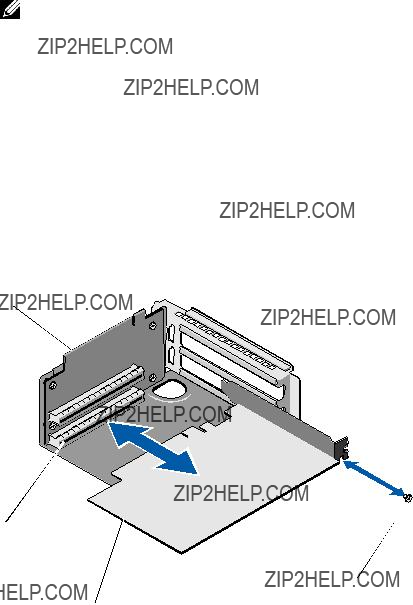
Removing the Integrated Storage Controller Card
CAUTION: Many repairs may only be done by a certified service technician. You should only perform troubleshooting and simple repairs as authorized in your product documentation, or as directed by the online or telephone service and support team. Damage due to servicing that is not authorized by Dell is not covered by your warranty. Read and follow the safety instructions that came with the product.
1Turn off the system, including any attached peripherals, and disconnect the system from its electrical outlet.
2Open the system. See "Opening the System" on page 58.
3Disconnect the SAS cables connected to the storage controller card.
4Lift the integrated storage controller card to remove it from the system board.
5Remove the three spacer pins and store them securely for later use. See Figure
Figure
3
2
1
 4
4
Installing the Integrated Storage Controller Card
CAUTION: Many repairs may only be done by a certified service technician. You should only perform troubleshooting and simple repairs as authorized in your product documentation, or as directed by the online or telephone service and support team. Damage due to servicing that is not authorized by Dell is not covered by your warranty. Read and follow the safety instructions that came with the product.
1Turn off the system, including any attached peripherals, and disconnect the system from its electrical outlet.
2Open the system. See "Opening the System" on page 58.
3Place the three spacer pins on the system board. See Figure

4Install the integrated storage controller card in place. See Figure
5Connect the SAS data cable to the integrated storage controller card.
6Close the system. See "Closing the System" on page 59.
7Reconnect the system to its electrical outlet and turn the system on, including any attached peripherals.
RAID Battery (Optional)
NOTE: The information in this section applies only to systems with the optional RAID controller card.
Removing a RAID Battery
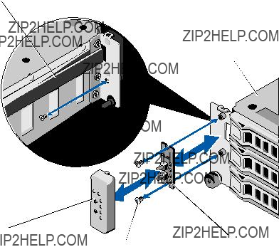
CAUTION: Many repairs may only be done by a certified service technician. You should only perform troubleshooting and simple repairs as authorized in your product documentation, or as directed by the online or telephone service and support team. Damage due to servicing that is not authorized by Dell is not covered by your warranty. Read and follow the safety instructions that came with the product.
1Turn off the system, including any attached peripherals, and disconnect the system from its electrical outlet.
2Open the system. See "Opening the System" on page 58.
3Locate the RAID battery carrier and remove the two screws that secure the RAID battery carrier on to the chassis. See Figure
4Pull back gently on the right edge of the battery bay and draw out the RAID battery from the battery carrier.
5Disconnect the cable between the RAID battery and the storage controller card. See Figure
Figure
2
3 
4 
Installing a RAID Battery
CAUTION: Many repairs may only be done by a certified service technician. You should only perform troubleshooting and simple repairs as authorized in your product documentation, or as directed by the online or telephone service and support team. Damage due to servicing that is not authorized by Dell is not covered by your warranty. Read and follow the safety instructions that came with the product.
1Connect the RAID battery cable to the connector on the RAID battery.
2With the cable oriented toward the back, angle the left side of the RAID battery into the left side of the battery carrier.
3Secure the RAID battery into the battery carrier.

4Secure the RAID battery carrier onto the chassis using the two screws. See Figure
5Connect the RAID battery cable to the RAID battery connector on the storage controller card. See Figure
6Close the system. See "Closing the System" on page 59.
7Reconnect your system and peripherals to their electrical outlets, and turn on the system.
Dual RAID Battery (Optional)
NOTE: The information in this section applies only to systems with the optional RAID controller card.
Removing a Dual RAID Battery
CAUTION: Many repairs may only be done by a certified service technician. You should only perform troubleshooting and simple repairs as authorized in your product documentation, or as directed by the online or telephone service and support team. Damage due to servicing that is not authorized by Dell is not covered by your warranty. Read and follow the safety instructions that came with the product.
1Turn off the system, including any attached peripherals, and disconnect the system from its electrical outlet.
2Open the system. See "Opening the System" on page 58.
3Locate the dual RAID battery carrier and remove the two screws that secure the battery carrier on to the chassis. See Figure
4Disconnect the cable between the RAID battery and the storage controller card. See Figure
5Slide the dual RAID battery carrier slightly toward the front of the system and lift it away from the system. See Figure
6Gently push the RAID batteries inside the battery carrier to free them of the battery carrier. See Figure

Figure
1
2
3

Figure
1 
2
Installing a RAID Battery
CAUTION: Many repairs may only be done by a certified service technician. You should only perform troubleshooting and simple repairs as authorized in your product documentation, or as directed by the online or telephone service and support team. Damage due to servicing that is not authorized by Dell is not covered by your warranty. Read and follow the safety instructions that came with the product.
1Connect the RAID battery cables to the connectors on the RAID batteries.
2With the cables oriented toward the back, secure the RAID batteries into the battery carrier. See Figure
3Affix the RAID battery carrier onto the chassis using the two screws. See Figure

4Connect the RAID battery cable to the RAID battery connector on the storage controller card. See Figure
5Close the system. See "Closing the System" on page 59.
6Reconnect your system and peripherals to their electrical outlets, and turn on the system.
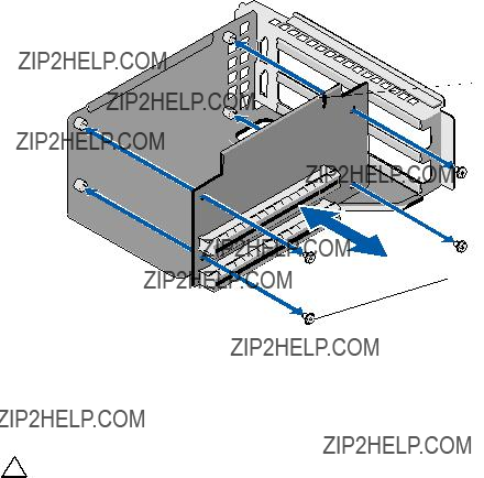
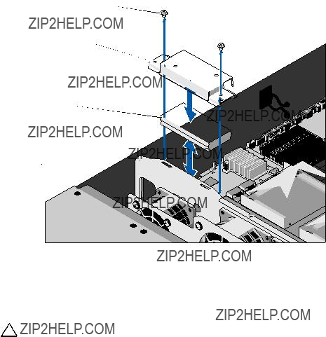
Mezzanine Card (10 GbE LAN)
Removing the Mezzanine Card (10 GbE LAN)
CAUTION: Many repairs may only be done by a certified service technician. You should only perform troubleshooting and simple repairs as authorized in your product documentation, or as directed by the online or telephone service and support team. Damage due to servicing that is not authorized by Dell is not covered by your warranty. Read and follow the safety instructions that came with the product.
1Turn off the system, including any attached peripherals, and disconnect the system from its electrical outlet.
2Open the system. See "Opening the System" on page 58.
3Remove the cooling shroud. See "Removing the Cooling Shroud" on page 60.
4Remove the
5Remove the three spacer pins and the screw on the mezzanine card.
6Remove the two screws securing the bracket and remove the card. See Figure
7If you are not installing another mezzanine card, install the
Figure
1
2
 3
3
5
 4
4

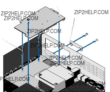
Installing the Mezzanine Card (10 GbE LAN)
CAUTION: Many repairs may only be done by a certified service technician. You should only perform troubleshooting and simple repairs as authorized in your product documentation, or as directed by the online or telephone service and support team. Damage due to servicing that is not authorized by Dell is not covered by your warranty. Read and follow the safety instructions that came with the product.
1If you are installing a mezzanine card for the first time, remove the two screws securing the
2Install a label bracket that has slots for connecting the mezzanine cards.
3Align the spacer pins on the mezzanine card with the holes on the system board.
NOTE: The three spacer pins must be inserted through the board for proper installation of the mezzanine card.
4Secure the board using the screw. See Figure
5Replace the
6Replace the cooling shroud. See "Installing the Cooling Shroud" on page 61.
7Replace the system cover. See "Closing the System" on page 59.
8Reconnect the system and peripherals to their electrical outlets, and turn on the system.

Power Supplies
WARNING: Whenever you need to lift the system, get others to assist you. To avoid injury, do not attempt to lift the system by yourself.
CAUTION: Many repairs may only be done by a certified service technician. You should only perform troubleshooting and simple repairs as authorized in your product documentation, or as directed by the online or telephone service and support team. Damage due to servicing that is not authorized by Dell is not covered by your warranty. Read and follow the safety instructions that came with the product.
Removing the Power Supply
WARNING: In order to reduce the risk of injury from electric shock, disconnect the failed power supply from the AC power before removing it from the system.
CAUTION: The system requires one power supply to operate the system normally. Remove and replace only one power supply at a time.
1Disconnect the power cable from the power supply.
2Press the lever release latch of the power supply and slide out the power supply using the power supply handle. See Figure
NOTE: Install a power supply blank if you are not replacing the power supply.
Figure
1
2
Installing the Power Supply
1Verify that both power supplies are of the same type and have the same maximum output power.
2Slide the new power supply into the system until the power supply is fully seated and the release latch snaps into place. See Figure
3Reconnect your system and peripherals to their electrical outlets, and turn on the system.
NOTE: When installing,

Removing the Power Supply Blank
CAUTION: To ensure proper system cooling, the power supply blank must be installed in power supply bay PS2 in a
To remove the power supply blank, remove the screw and pull outward on the blank.
Installing the Power Supply Blank
NOTE: Install the power supply blank only in power supply bay 2.
Align the blank with the power supply bay and insert the blank into the chassis until it clicks into place. Secure with screw.
Power Distribution Board
WARNING: Whenever you need to lift the system, get others to assist you. To avoid injury, do not attempt to lift the system by yourself.
CAUTION: Many repairs may only be done by a certified service technician. You should only perform troubleshooting and simple repairs as authorized in your product documentation, or as directed by the online or telephone service and support team. Damage due to servicing that is not authorized by Dell is not covered by your warranty. Read and follow the safety instructions that came with the product.
The power distribution board comes as a power distribution board assembly with two power distribution boards.
Removing the Power Distribution Board Assembly
1Turn off the system, including any attached peripherals, and disconnect the system from its electrical outlet.
2Remove the system from the rack and place on a flat surface.
3Remove the right side rail from the chassis.
4Remove the two screws on the side of the chassis. See Figure
5Open the system. See "Opening the System" on page 58.
6Disconnect all the power cables from the power distribution board.
7Remove the two screws that secure the power distribution board assembly to the bottom of the chassis. See Figure

Figure
1
2
3 
3 power distribution boards (2)
Installing the Power Distribution Board Assembly
CAUTION: Many repairs may only be done by a certified service technician. You should only perform troubleshooting and simple repairs as authorized in your product documentation, or as directed by the online or telephone service and support team. Damage due to servicing that is not authorized by Dell is not covered by your warranty. Read and follow the safety instructions that came with the product.
1Place the power distribution board assembly into the system and align the slots on the power distribution board assembly with the slots on the chassis.

2Replace the two screws that secure the power distribution board assembly to the bottom of the chassis.
3Connect all the power cables. See Figure
4Replace the system cover. See "Closing the System" on page 59.
5Replace the two screws on the right side of the chassis.
6Replace the right side rail.
7Reconnect the system and peripherals to their electrical outlets, and turn on the system.
Cooling Fans
WARNING: The cooling fan can continue to spin for some time after the system has been powered down. Allow time for the fan to stop spinning before removing it from the system.
WARNING: Do not attempt to operate the system without the cooling fans.
CAUTION: Many repairs may only be done by a certified service technician. You should only perform troubleshooting and simple repairs as authorized in your product documentation, or as directed by the online or telephone service and support team. Damage due to servicing that is not authorized by Dell is not covered by your warranty. Read and follow the safety instructions that came with the product.
Removing a Cooling Fan Assembly
1Turn off the system, including any attached peripherals, and disconnect the system from its electrical outlet.
2Open the system. See "Opening the System" on page 58.
3Disconnect the three power cables from the backplane. See Figure
4Remove the single screw that secures the fan assembly to the chassis. See Figure
5Slide the fan assembly slightly toward the front of the system and lift it away from the system. See Figure

Figure
1
2
3
Installing the Cooling Fan Assembly
1Place the fan assembly into the system and slide the fan assembly slightly toward the back of the system.
2Align the slot on the fan assembly with the slot on the chassis.
3Replace the screw that secures the fan assembly to the chassis.
4Connect the power cables to the cooling fans. See Figure
5Replace the system cover. See "Closing the System" on page 59.
6Reconnect the system and peripherals to their electrical outlets, and turn on the system.

Removing the Fan Module
Remove the four screws that secure the fan module to the fan assembly and separate the fan module from the fan assembly. See Figure
Figure
1
4
2
3

Installing the Fan Module
NOTE: Note the direction of airflow on the fan modules and ensure that the fan modules are oriented in the correct direction while installing.
Align the slots on the fan module with the slots on the fan assembly such that the labelled side faces the back of the system. Secure the fan module to the fan assembly using the screws. See Figure
Backplane
CAUTION: Many repairs may only be done by a certified service technician. You should only perform troubleshooting and simple repairs as authorized in your product documentation, or as directed by the online or telephone service and support team. Damage due to servicing that is not authorized by Dell is not covered by your warranty. Read and follow the safety instructions that came with the product.
Removing the Backplane
1Turn off the system, including any attached peripherals, and disconnect the system from its electrical outlet.
2Open the system. See "Opening the System" on page 58.
3Remove the cooling fan assembly. See "Removing a Cooling Fan Assembly" on page 94.
4Disconnect the SAS/SATA cables, the fan cables, and the power cables from the backplane. See Figure
CAUTION: To prevent damage to the drives and backplane, you must remove the hard drives from the system before removing the backplane.
CAUTION: You must note the number of each hard drive and temporarily label them before removal so that you can replace them in the same locations.
5Remove all the hard drives. See "Removing a
6Remove the three screws that secure the backplane to the system. See Figure
7Slide the backplane and lift it clear off the system.

Figure
2
1

Installing the Backplane
1Insert the backplane in the direction of the arrow until it is seated in the system.
2Secure the backplane to the system using the three screws.
3Replace all the hard drives in the system. See "Installing a
4Replace the cooling fan assembly. "Installing the Cooling Fan Assembly" on page 95.
5Connect the SAS/SATA cables, the fan cables, and the power cable. See Figure
6Replace the cooling shroud. See "Installing the Cooling Shroud" on page 61.
7Replace the system cover. See "Closing the System" on page 59.
8Reconnect the system and peripherals to their electrical outlets, and turn on the system.
Control Panel Assembly
CAUTION: Many repairs may only be done by a certified service technician. You should only perform troubleshooting and simple repairs as authorized in your product documentation, or as directed by the online or telephone service and support team. Damage due to servicing that is not authorized by Dell is
not covered by your warranty. Read and follow the safety instructions that came with the product.
Removing the Control Panel Assembly
1Turn off the system, including any attached peripherals, and disconnect the system from its electrical outlet.
2Open the system. See "Opening the System" on page 58.
3Remove the cooling shroud. See "Removing the Cooling Shroud" on page 60.
4Slide the cable cover on the side of the system, toward the back of the system to remove it.
5Disconnect the LED signal cable from the front panel connector on the system board. See Figure
6Remove the screw securing the LED panel cover to the chassis and slide the cover out. See Figure
7Remove the two screws securing the control panel assembly to the chassis. See Figure
8Remove the control panel assembly.
Figure
1
2
5
Installing the Control Panel Assembly
CAUTION: Many repairs may only be done by a certified service technician. You should only perform troubleshooting and simple repairs as authorized in your product documentation, or as directed by the online or telephone service and support team. Damage due to servicing that is not authorized by Dell is
not covered by your warranty. Read and follow the safety instructions that came with the product.
1Place the control panel assembly onto the front of the system and secure in place with the two screws.
2Replace the control panel assembly cover and secure it with the screw.
3Connect the LED signal cable to the front panel connector on the system board. See Figure
4Replace the cable cover making sure that the cables are not crimped.
5Replace the cooling shroud. See "Installing the Cooling Shroud" on page 61.
6Replace the system cover. See "Closing the System" on page 59.
7Reconnect the system and peripherals to their electrical outlets, and turn on the system.
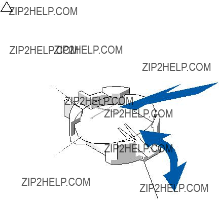
System Battery
Removing the System Battery
WARNING: There is a danger of a new battery exploding if it is incorrectly installed. Replace the battery only with the same or equivalent type recommended by the manufacturer. See your safety information for additional information.
CAUTION: Many repairs may only be done by a certified service technician. You should only perform troubleshooting and simple repairs as authorized in your product documentation, or as directed by the online or telephone
service and support team. Damage due to servicing that is not authorized by Dell is not covered by your warranty. Read and follow the safety instructions that came with the product.
1Turn off the system, including any attached peripherals, and disconnect the system from the electrical outlet.
2Open the system. See "Opening the System" on page 58.
3Remove the cooling shroud. See "Removing the Cooling Shroud" on page 60.
4Locate the battery socket. See "System Board Connectors" on page 125.
CAUTION: To avoid damage to the battery connector, you must firmly support the connector while installing or removing a battery.
5Slide the battery toward the positive side of the connector and lift it out of the securing tabs at the negative side of the connector.
Figure
1
2
Installing the System Battery
1Hold the battery with the "+" facing up, and slide it under the securing tabs at the positive side of the connector.
2Press the battery straight down into the connector until it snaps into place.
3Install the cooling shroud. See "Installing the Cooling Shroud" on page 61.
4Close the system. See "Closing the System" on page 59.

5Reconnect the system to the electrical outlet and turn the system on, including any attached peripherals.
6Enter the System Setup program to confirm that the battery is operating properly. See "Using the System Setup Program" on page 37.
7Enter the correct time and date in the System Setup program's Time and Date fields, and
8Exit the System Setup program.
System Board
WARNING: Whenever you need to lift the system, get others to assist you. To avoid injury, do not attempt to lift the system by yourself.
CAUTION: Many repairs may only be done by a certified service technician. You should only perform troubleshooting and simple repairs as authorized in your product documentation, or as directed by the online or telephone service and support team. Damage due to servicing that is not authorized by Dell is not covered by your warranty. Read and follow the safety instructions that came with the product.
Removing the System Board
1Turn off the system and attached peripherals, and disconnect the system from the electrical outlet.
2Open the system. See "Opening the System" on page 58.
3Remove the cooling shroud. See "Removing the Cooling Shroud" on page 60.
4Remove all memory modules. See "Removing Memory Modules" on page 71.
5Remove the expansion
6Remove the heat sinks. See "Removing the Heat Sink" on page 62.
7Remove the processors. See "Removing the Processor" on page 64.
8Disconnect the power, SATA, and front panel cables from the system board.
CAUTION: Do not lift the system board assembly by grasping a memory module, processor, or other components.

9Loosen the ten screws securing the system board, and then slide the board toward the front, up and out of the system. See Figure
Figure
1
2
Installing the System Board
1Align the holes A and B on the system board to position the board correctly in the system.
2Replace the ten screws to secure the system board in place.
3Reconnect the power, SATA, and front panel cables to the system board. See "System Board Connectors" on page 125.
4Replace the processors. See "Installing the Processor" on page 66.
5Replace the heat sinks. See "Installing the Heat Sink" on page 64.
6Replace the
7Replace the memory modules. See "Installing Memory Modules" on page 72.
8Replace the cooling shroud. See "Installing the Cooling Shroud" on page 61.
9Replace the system cover. See "Closing the System" on page 59.
10Reconnect the system and peripherals to their electrical outlets, and turn on the system.

Troubleshooting Your System
Safety
WARNING: Whenever you need to lift the system, get others to assist you. To avoid injury, do not attempt to lift the system by yourself.
WARNING: Before removing the system cover, disconnect all power, then unplug the AC power cord, and then disconnect all peripherals, and all LAN lines.
CAUTION: Many repairs may only be done by a certified service technician. You should only perform troubleshooting and simple repairs as authorized in your product documentation, or as directed by the online or telephone service and support team. Damage due to servicing that is not authorized by Dell is not covered by your warranty. Read and follow the safety instructions that came with the product.
Installation Problems
Perform the following checks if you are troubleshooting an installation problem:
???Check all cable and power connections (including all rack cable connections).
???Unplug the power cord and wait for one minute. Then reconnect the power cord and try again.
???If the network is reporting an error, verify that the system has enough memory and disk space.
???Remove all added peripherals, one at a time, and try to turn on the system. If after removing a peripheral the system works, it may be a problem with the peripheral or a configuration problem between the peripheral and the system. Contact the peripheral vendor for assistance.
???If the system does not power on, check the LED display. If the power LED is not on, you may not be receiving AC power. Check the AC power cord to make sure that it is securely connected.
Troubleshooting System Startup Failure
If your system halts during startup prior to video imaging, especially after installing an operating system or reconfiguring your system???s hardware, see "System Memory" on page 67.
For all other startup issues, note the LED panel indicators and any system messages that appear on screen. For more information, see "Power and System Board Status Codes" on page 17 for more information.
Troubleshooting External Connections
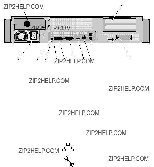
Ensure that all external cables are securely attached to the external connectors on your system before troubleshooting any external devices. See Figure
Troubleshooting the Video Subsystem
1Check the system and power connections to the monitor.
2Check the video interface cabling from the system to the monitor.
Troubleshooting a USB Device
Use the following steps to troubleshoot a USB keyboard and/or mouse. For other USB devices, go to step 5.
1Disconnect the keyboard and mouse cables from the system briefly and reconnect them.
2Connect the keyboard/mouse to the USB port(s) on the opposite side of the system.
3If the problem is resolved, restart the system, enter the System Setup program, and check if the nonfunctioning USB ports are enabled.
4Replace the keyboard/mouse with another working keyboard/mouse. If the problem is resolved, replace the faulty keyboard/mouse.
If the problem is not resolved, proceed to the next step to begin troubleshooting the other USB devices attached to the system.
5Turn off all attached USB devices and disconnect them from the system.
6Restart the system and, if your keyboard is functioning, enter the system setup program. Verify that all USB ports are enabled. See "USB Configuration" on page 43.
If your keyboard is not functioning, you can also use remote access. If the system is not accessible, see "Jumper Settings" on page 123 for instructions on setting the NVRAM_CLR jumper inside your system and restoring the BIOS to the default settings.
7Reconnect and turn on each USB device one at a time.
8If a device causes the same problem, turn off the device, replace the USB cable, and turn on the device.
If the problem persists, replace the device.
If all troubleshooting fails, see "Getting Help" on page 131.
Troubleshooting a Serial I/O Device
1Turn off the system and any peripheral devices connected to the serial port.
2Swap the serial interface cable with another working cable, and turn on the system and the serial device.
If the problem is resolved, replace the interface cable.
3Turn off the system and the serial device, and swap the device with a comparable device.
4Turn on the system and the serial device.
If the problem is resolved, replace the serial device.
If the problem persists, see "Getting Help" on page 131.
Troubleshooting a NIC
1Restart the system and check for any system messages pertaining to the NIC controller.
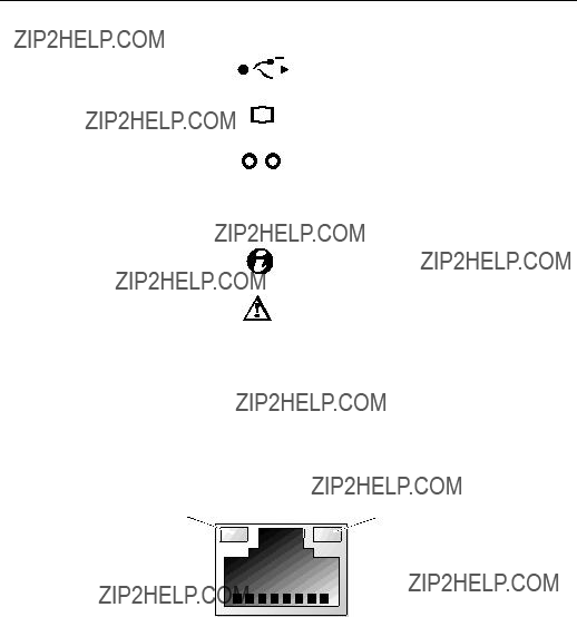
2Check the appropriate indicator on the NIC connector. See "NIC Indicator Codes" on page 15.
???If the link indicator does not light, check all cable connections.
???If the activity indicator does not light, the network driver files might be damaged or missing.
Remove and reinstall the drivers if applicable. See the NIC's documentation.
???Change the
???Use another connector on the switch or hub.
If you are using a NIC card instead of an integrated NIC, see the documentation for the NIC card.
3Ensure that the appropriate drivers are installed and the protocols are bound. See the NIC's documentation.
4Enter the System Setup program and confirm that the NIC ports are enabled. See "NIC Indicator
5Ensure that the NICs, hubs, and switches on the network are all set to the same data transmission speed. See the documentation for each network device.
6Ensure that all network cables are of the proper type and do not exceed the maximum length.
If all troubleshooting fails, see "Getting Help" on page 131.
Troubleshooting a Wet System
CAUTION: Many repairs may only be done by a certified service technician. You should only perform troubleshooting and simple repairs as authorized in your product documentation, or as directed by the online or telephone service and support team. Damage due to servicing that is not authorized by Dell is not covered by your warranty. Read and follow the safety instructions that came with the product.
1Turn off the system and attached peripherals, and disconnect the system from the electrical outlet.
2Open the system. See "Opening the System" on page 58.
3Disassemble components from the system. See "Installing System Components" on page 51.
???Cooling shroud
???Hard drives
???Backplane
???
???Power supplies
???Fans
???Processors and heat sinks
???Memory modules
4Let the system dry thoroughly for at least 24 hours.
5Reinstall the components you removed in step 3.
6Close the system. See "Closing the System" on page 59.
7Reconnect the system to the electrical outlet, and turn on the system and attached peripherals.
If the system does not start properly, see "Getting Help" on page 131.
8If the system starts properly, shut down the system and reinstall all of
the expansion cards that you removed. See "Installing the Expansion Card" on page 79.
9If the system fails to start, see "Getting Help" on page 131.

Troubleshooting a Damaged System
CAUTION: Many repairs may only be done by a certified service technician. You should only perform troubleshooting and simple repairs as authorized in your product documentation, or as directed by the online or telephone service and support team. Damage due to servicing that is not authorized by Dell is not covered by your warranty. Read and follow the safety instructions that came with the product.
1Turn off the system and attached peripherals, and disconnect the system from the electrical outlet.
2Open the system. See "Opening the System" on page 58.
3Ensure that the following components are properly installed:
???
???Power supplies
???Fans
???Hard drives
???Processors and heat sinks
???Memory modules
???Cooling shroud
4Ensure that all cables are properly connected.
5Close the system. See "Closing the System" on page 59.
6If the system fails to start, see "Getting Help" on page 131.
Troubleshooting the System Battery
NOTE: If the system is turned off for long periods of time (for weeks or months), the NVRAM may lose its system configuration information. This situation is caused by a defective battery.
1
2Turn off the system and disconnect it from the electrical outlet for at least one hour.
3Reconnect the system to the electrical outlet and turn on the system.

4Enter the System Setup program.
If the date and time are not correct in the System Setup program, replace the battery. See "Installing the System Battery" on page 102.
If the problem is not resolved by replacing the battery, see "Getting Help" on page 131.
CAUTION: Many repairs may only be done by a certified service technician. You should only perform troubleshooting and simple repairs as authorized in your product documentation, or as directed by the online or telephone service and support team. Damage due to servicing that is not authorized by Dell is not covered by your warranty. Read and follow the safety instructions that came with the product.
NOTE: Some software may cause the system time to speed up or slow down. If the system seems to operate normally except for the time kept in the
System Setup program, the problem may be caused by software rather than by a defective battery.
Troubleshooting Power Supplies
1Identify the faulty power supply by the power supply's fault indicator. See "Power and System Board Status Codes" on page 17.
CAUTION: At least one power supply must be installed for the system to operate. Operating the system with only one power supply installed for extended periods of time can cause the system to overheat.
2Reseat the power supply by removing and reinstalling it. See "Installing the Power Supply" on page 91 or "Removing the Power Supply" on page 90.
NOTE: After installing a power supply, allow several seconds for the system to recognize the power supply and to determine if it is working properly. The power indicator turns green to signify that the power supply is functioning properly.
If the problem persists, replace the faulty power supply.
3 If all troubleshooting fails, see "Getting Help" on page 131.

Troubleshooting System Cooling Problems
CAUTION: Many repairs may only be done by a certified service technician. You should only perform troubleshooting and simple repairs as authorized in your product documentation, or as directed by the online or telephone service and support team. Damage due to servicing that is not authorized by Dell is not covered by your warranty. Read and follow the safety instructions that came with the product.
Ensure that none of the following conditions exist:
???System cover, cooling shroud, drive blank, power supply blank, or front or back filler panel is removed.
???Ambient temperature is too high.
???External airflow is obstructed.
???Cables inside the system obstruct airflow.
???An individual cooling fan is removed or has failed. See "Troubleshooting a Fan" on page 114.
Troubleshooting a Fan
CAUTION: Many repairs may only be done by a certified service technician. You should only perform troubleshooting and simple repairs as authorized in your product documentation, or as directed by the online or telephone service and support team. Damage due to servicing that is not authorized by Dell is not covered by your warranty. Read and follow the safety instructions that came with the product.
1Locate the faulty fan indicated by the LED panel.
2Turn off the system and all attached peripherals.
3Open the system. See "Opening the System" on page 58.
4Reseat the fan's power cable.
5Restart the system.
If the fan functions properly, close the system. See "Closing the System" on page 59.

6If the fan does not function, turn off the system and install a new fan. See "Installing the Cooling Fan Assembly" on page 95.
7Restart the system.
If the problem is resolved, close the system. See "Closing the System" on page 59.
If the replacement fan does not operate, see "Getting Help" on page 131.
Troubleshooting System Memory
CAUTION: Many repairs may only be done by a certified service technician. You should only perform troubleshooting and simple repairs as authorized in your product documentation, or as directed by the online or telephone service and support team. Damage due to servicing that is not authorized by Dell is not covered by your warranty. Read and follow the safety instructions that came with the product.
NOTE: Invalid memory configurations can cause your system to halt at startup without video output. See "General Memory Module Installation Guidelines" on page 68 and verify that your memory configuration complies with all applicable guidelines.
1If the system is not operational, turn off the system and attached peripherals, and unplug the system from the power source. Wait at least 10 seconds and then reconnect the system to power.
2Turn on the system and attached peripherals and note the messages on the screen.
Go to step 13 if an error message appears indicating a fault with a specific memory module.
3Enter the System Setup program and check the system memory setting. See "Memory Configuration" on page 42. Make any changes to the memory settings, if needed.
If the memory settings match the installed memory but a problem is still indicated, go to step 13.
4Turn off the system and attached peripherals, and disconnect the system from the electrical outlet.
5Open the system. See "Opening the System" on page 58.
6Remove the cooling shroud. See "Removing the Cooling Shroud" on page 60.
7Check the memory channels and ensure that they are populated correctly. See "General Memory Module Installation Guidelines" on page 68.
8Reseat the memory modules in their sockets. See "Installing Memory Modules" on page 72.
9Replace the cooling shroud. See "Installing the Cooling Shroud" on page 61.
10Close the system. See "Closing the System" on page 59.
11Reconnect the system to its electrical outlet, and turn on the system and attached peripherals.
12Enter the System Setup program and check the system memory setting. See "System Memory Settings" on page 40.
If the problem is not resolved, proceed with the next step.
13Turn off the system and attached peripherals, and disconnect the system from the power source.
14Open the system. See "Opening the System" on page 58.
15If an error message indicates a specific memory module as faulty, swap or replace the module.
16To troubleshoot an unspecified faulty memory module, replace the memory module in the first DIMM socket with a module of the same type and capacity. See "Installing Memory Modules" on page 72.
17Close the system. See "Closing the System" on page 59.
18Reconnect the system to its electrical outlet, and turn on the system and attached peripherals.
19As the system boots, observe any error message that appears and the LED indicators on the front of the system.
20If the memory problem is still indicated, repeat step 13 through step 19 for each memory module installed.
If the problem persists after all memory modules have been checked, see "Getting Help" on page 131.

Troubleshooting a Hard Drive
CAUTION: Many repairs may only be done by a certified service technician. You should only perform troubleshooting and simple repairs as authorized in your product documentation, or as directed by the online or telephone service and support team. Damage due to servicing that is not authorized by Dell is not covered by your warranty. Read and follow the safety instructions that came with the product.
CAUTION: This troubleshooting procedure can destroy data stored on the hard drive. Before you proceed, back up all files on the hard drive.
1If your system has a RAID controller and your hard drives are configured in a RAID array, perform the following steps:
aRestart the system and enter the host adapter configuration utility program by pressing <Ctrl><R> for a PERC controller or <Ctrl><C> for a SAS controller.
See the documentation supplied with the host adapter for information about the configuration utility.
bEnsure that the hard drive(s) have been configured correctly for the RAID array.
cTake the hard drive offline and reseat the drive. See "Removing a
dExit the configuration utility and allow the system to boot to the operating system.
2Ensure that the required device drivers for your controller card are installed and are configured correctly. See the operating system documentation for more information.
3Restart the system, enter the System Setup program, and verify that the controller is enabled and the drives appear in the System Setup program. See "Using the System Setup Program" on page 37.
If the problem persists, see "Getting Help" on page 131.

Troubleshooting a Storage Controller
NOTE: When troubleshooting a SAS or SAS RAID controller, also see the documentation for your operating system and the controller.
1Enter the System Setup program and ensure that the SAS controller is enabled. See "System Setup Options at Boot" on page 38.
2Restart the system and press the applicable key sequence to enter the configuration utility program.
???<Ctrl><C> for a SAS controller
???<Ctrl><R> for a RAID controller
See the controller's documentation for information about configuration settings.
3Check the configuration settings, make any necessary corrections, and restart the system.
CAUTION: Many repairs may only be done by a certified service technician. You should only perform troubleshooting and simple repairs as authorized in your product documentation, or as directed by the online or telephone service and support team. Damage due to servicing that is not authorized by Dell is not covered by your warranty. Read and follow the safety instructions that came with the product.
4Turn off the system and attached peripherals, and disconnect the system from its electrical outlet.
5Remove the
6Ensure that the controller card is firmly seated into the system board connector. See "Installing the Expansion Card" on page 79.
7If you have a
8Verify that the cable connections between the SAS backplane(s) and the integrated storage controller are correct.
Ensure that the cables are firmly connected to the storage controller and the SAS backplane board.

9Install the
10Reconnect the system to its electrical outlet, and turn on the system and attached peripherals.
If the problem persists, see "Getting Help" on page 131.
Troubleshooting Expansion Cards
CAUTION: Many repairs may only be done by a certified service technician. You should only perform troubleshooting and simple repairs as authorized in your product documentation, or as directed by the online or telephone service and support team. Damage due to servicing that is not authorized by Dell is not covered by your warranty. Read and follow the safety instructions that came with the product.
NOTE: When troubleshooting an expansion card, see the documentation for your operating system and the expansion card.
1Turn off the system and attached peripherals, and disconnect the system from the electrical outlet.
2Open the system. See "Opening the System" on page 58.
3Ensure that each expansion card is firmly seated in its connector. See "Installing the Expansion Card" on page 79.
4Ensure that the
5Close the system. See "Closing the System" on page 59.
6Reconnect the system to the electrical outlet, and turn on the system and attached peripherals.
7If the problem is not resolved, turn off the system and attached peripherals, and disconnect the system from the electrical outlet.
8Open the system. See "Opening the System" on page 58.
9Remove all expansion cards installed in the system. See "Removing the Expansion Card" on page 77.
10Close the system. See "Closing the System" on page 59.
11Reconnect the system to the electrical outlet, and turn on the system and attached peripherals.

12For each expansion card you removed in step 9, perform the following steps:
a Turn off the system and attached peripherals, and disconnect the system from the electrical outlet.
b Open the system. See "Opening the System" on page 58. c Reinstall one of the expansion cards.
d Close the system. See "Closing the System" on page 59.
Troubleshooting Processors
CAUTION: Many repairs may only be done by a certified service technician. You should only perform troubleshooting and simple repairs as authorized in your product documentation, or as directed by the online or telephone service and support team. Damage due to servicing that is not authorized by Dell is not covered by your warranty. Read and follow the safety instructions that came with the product.
1Turn off the system and attached peripherals, and disconnect the system from the electrical outlet.
2Open the system. See "Opening the System" on page 58.
3Ensure that each processor and heat sink are properly installed. See "Installing the Processor" on page 66.
4Close the system. See "Closing the System" on page 59.
5Reconnect the system to the electrical outlet, and turn on the system and attached peripherals.
6If the problem is not resolved, turn off the system and attached peripherals, and disconnect the system from the electrical outlet.
7Open the system. See "Opening the System" on page 58.
8Remove processor 2. See "Removing the Processor" on page 64.
9Close the system. See "Closing the System" on page 59.
10Reconnect the system to the electrical outlet, and turn on the system and attached peripherals.
11If the problem is not resolved, turn off the system and attached peripherals, and disconnect the system from the electrical outlet.
12Open the system. See "Opening the System" on page 58.
13Replace processor 1 with processor 2. See "Installing the Processor" on page 66.
14Repeat step 9 through step 11.
If you have tested both the processors and the problem persists, the system board is faulty. See "Getting Help" on page 131.
IRQ Assignment Conflicts
Most PCI devices can share an IRQ with another device, but they cannot use an IRQ simultaneously. To avoid this type of conflict, see the documentation for each PCI device for specific IRQ requirements.
Table

Troubleshooting Changes in BIOS Settings
Certain changes in BIOS settings (such as chipset timing or latency, memory timing or latency, processor clock frequency, etc.) can cause a system to stop booting.
If you are able to enter the BIOS Setup by pressing F2, reset the BIOS to factory defaults by pressing F9. Save and exit the BIOS Setup.
If you cannot enter the BIOS Setup, clear the CMOS by following instructions given below:
1Turn off the system. Do not unplug the power cord.
2Open the system. See "Opening the System" on page 58.
3Move jumper (J24) from the default operation position, covering pins 1 and 2, to the reset / clear position, remove the cover from pins 1 and 2.
4Remove AC power and wait 5 seconds.
5Move the jumper back to default position, covering pins 1 and 2.
6Close the system.
7Turn on the system.
The CMOS is now cleared and can be reset by going into BIOS setup.
NOTE: Removing the AC power before performing the CMOS Clear operation causes the system to automatically turn on and immediately turn off, after the procedure is followed and AC power is
You may also need to perform a BIOS bank select after clearing the CMOS.

Jumpers and Connectors
Jumper Settings
CAUTION: Many repairs may only be done by a certified service technician. You should only perform troubleshooting and simple repairs as authorized in your product documentation, or as directed by the online or telephone service and support team. Damage due to servicing that is not authorized by Dell is not covered by your warranty. Read and follow the safety instructions that came with the product.
System Configuration Jumper Settings
Figure
JP21
JP24
Table

Table
NOTE: The "*" in the table of system configuration jumpers describes the default status and the default state is not active state.
Backplane Jumper Settings
CAUTION: Many repairs may only be done by a certified service technician. You should only perform troubleshooting and simple repairs as authorized in your product documentation, or as directed by the online or telephone service and support team. Damage due to servicing that is not authorized by Dell is not covered by your warranty. Read and follow the safety instructions that came with the product.
Figure
The function of the jumper installed on the expander backplane is shown below.
Table


Backplane Connectors
Figure
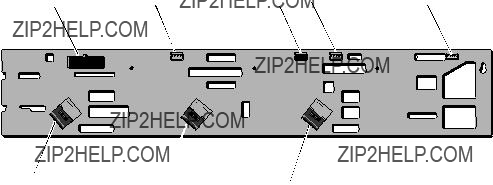
Figure

Power Distribution Board Connectors
Figure
2
 4
4

Figure
Getting Help
Contacting Dell
For customers in the United States, call
NOTE: If you do not have an active Internet connection, you can find contact information on your purchase invoice, packing slip, bill, or Dell product catalog.
Dell provides several online and
1Visit support.dell.com.
2Click your country/region at the bottom of the page. For a full listing of country/region click All.
3Click All Support from Support menu.
4Select the appropriate service or support link based on your need.
5Choose the method of contacting Dell that is convenient for you.

Index
Numerics
10 GbE LAN Mezzanine card installing, 89
A
B
backplane installing, 99 removing, 97
batteries troubleshooting, 112
battery
troubleshooting the RAID card battery, 118
battery (system) installing, 101 removing, 102
blank
BMC LAN configuring, 48
boot settings configuring, 45
C
closing system, 59
configuring BMC LAN, 48 boot settings, 45 IDE, 42 memory, 42 processor, 41 remote access, 49 super IO, 43 USB, 43
control panel assembly installing, 101 removing, 99
cooling fan installing, 95 removing, 94
cooling fans troubleshooting, 114
Index 133

D
damaged systems troubleshooting, 112
Dell
DIMMs
See memory modules (DIMMs)
E
expansion card troubleshooting, 119
expansion cards SAS controller, 80
F
features
G
guidelines
H
hard drive installing, 56 removing, 54 troubleshooting, 117
Hard Drives
hard drives installing, 53
heat sink installing, 64 removing, 62
I
IDE configuring, 42
indicator codes
installing
10 GbE LAN Mezzanine card, 89 backplane, 99
control panel assembly, 101 cooling fan, 95
cooling shroud, 61
heat sink, 63 memory modules, 72 power supply, 91 power supply blank, 92 processor, 66
134 Index

SAS controller, 81 system battery, 101 system board, 104 system cover, 59
K
keyboards troubleshooting, 108
M
memory configuration, 70 configuring, 42 troubleshooting, 115
memory mode optimizer, 69
memory modules installing, 72 removing, 71
memory modules (DIMMs) configuring, 68
N
NICs
O
opening system, 58
P
PCI
POST
power supply installing, 91
processor, 64 configuring, 41 installing, 66 removing, 64
processors troubleshooting, 120
R
remote access configuring, 49
removing
10 GbE LAN Mezzanine card, 87 backplane, 97
control panel assembly, 99 cooling fan, 94
Index 135

memory modules, 71 power supply blank, 92 processor, 64
SAS controller, 80 system battery, 102 system board, 103
S
SAS controller card installing, 81 removing, 80
SAS controller daughter card troubleshooting, 118
SAS RAID controller daughter card
startup
super IO configuring, 43
support
system closing, 59 opening, 58
system cooling troubleshooting, 114
system cover installing, 59
system features accessing, 9
system setup AMBIOS, 40 processor settings, 40 system memory, 40
T
Troubleshooting
troubleshooting battery, 112 cooling fans, 114 damaged system, 112 expansion card, 119
external connections, 108 hard drive, 117 keyboard, 108
memory, 115 NIC, 110 processors, 120
Index 136

138 Index


