C H A P T E R 4

Setting Up Host Servers

This chapter helps you set up and configure host servers attached to the PowerVault 530F storage area network (SAN) appliance and includes the following procedures:

???Installing the host bus adapter (HBA) on Windows NT and Windows 2000

???Installing the QLogic Fibre Channel Configuration Utility on a host

???Installing QLDirect

???Setting the execution throttle value

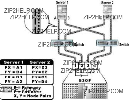
???Setting failover paths

???Registering host servers

???Configuring the QLogic 2200 or 2200F HBA to boot through the PowerVault 530F (optional feature)

NOTE: Before setting up host servers, complete the initial setup procedures detailed in Chapter 2, ???Getting Started,??? and Chapter 3, ???Setting Up the PowerVault 650F and 660F Storage Subsystems.???

Installing the HBA on Windows NT and Windows 2000

When configuring host servers, you must first install the HBA drivers. The drivers for the Windows NT and Windows 2000 operating systems are located on the Dell PowerVault Fibre Channel Utilities CD or the Dell PowerVault Fibre Channel Update CD.

Installing the QLogic Fibre Channel Configuration Utility on a Host

For the SAN to function properly when connected to a PowerVault 530F, you must install and run the QLogic Fibre Channel Configuration Utility. This utility is also neces- sary to configure host failover. However, to obtain the host failover functionality, you must also install QLDirect (see ???Installing QLDirect??? found later in this chapter).

Install the QLogic Fibre Channel Configuration Utility on host servers from the Dell PowerVault Fibre Channel Utilities CD or the Dell PowerVault Fibre Channel Update CD. This utility includes a user interface, as well as the Windows NT agent and the Intel Desktop Management Interface (DMI). Install the Windows NT agent and the Intel DMI on every host server that will be connected to the PowerVault 530F. Install the user interface on one of the host servers or on a workstation being used for management.

Installing the QLogic Fibre Channel Configuration Utility on Host Servers

To install the QLogic Fibre Channel Configuration Utility on a host server, perform the following steps:

1.Insert the Dell PowerVault Fibre Channel Utilities CD or the Dell PowerVault Fibre Channel Update CD into the CD-ROM drive.

NOTE: You must run the installation program once on each host server connected to the PowerVault 530F. In addition, to maintain the appropriate settings for device replacement, you must run the QLogic Fibre Channel Configuration Utility each time hardware on the SAN changes.

2.Begin the QLogic Fibre Channel Configuration Utility installation.

3.Read the component information, and click Next.

4.Read the software license agreement, and click Next.

5.Select the desired components.

For a Windows NT 4.0 or Windows 2000 installation select the following components:

???QLConfig application

???QLConfig agent

6.Select the desired destination folder, and click Next.

7.After the Intel DMI 2.0 Service Provider installation begins, click Next.

8.Read the license agreement, and click Next.

9.Make sure the win32sl services/process is stopped.

10.Make sure both of the following components are selected:

???DMI 2.0 Service Provider

???DMI 2.0 Client

11.Select the desired program folder, and click Next.

12.Click OK.

4-2 System Administrator???s Guide

13.To add a shortcut to your desktop, click Yes.

14.You are prompted to reboot the system. While it is possible to reboot at this time, you can also wait to reboot until you have finished installing QLDirect (see ???Installing QLDirect??? in the next section).

NOTE: If you are uninstalling the QLogic Fibre Channel Configuration Utility, or you replace or uninstall a QLogic HBA, you must delete the appropriate server's registry settings. To delete these settings, from the QLogic Fibre Channel Configuration Util- ity, right-click on the server's icon, and then select Delete Machine Configuration Registry and click Delete All Adapters Registry Data.

Installing QLDirect

QLDirect is a filter driver that enables host failover. This driver must be installed on every host server that will be connected to the PowerVault 530F. Specific primary and failover paths are configured using the QLogic Fibre Channel Configuration Utility.

Installing QLDirect on a Host Server

To install QLDirect on a host server, perform the following steps:

1.Insert the Dell PowerVault Fibre Channel Utilities CD or the Dell PowerVault Fibre Channel Update CD into the CD-ROM drive.

NOTE: Run the installation program once for each host server connected to the PowerVault 530F.

2.Start the QLDirect installation.

3.Read the component information, and click Next.

4.Select SERVICE_BOOT_START before disk class driver, and click Next.

5.Select 1024 commands, and click Next.

6.Select Yes, I want to restart my computer now, and click Finish.

Setting the Execution Throttle Value

The execution throttle value field instructs the firmware on how many input/output (I/Os) per port can be active at any point in time.

If five or more servers are attached to the PowerVault 530F, it is necessary to calcu- late and set execution throttle values for each server.

In a SAN configuration with five or more servers, you must change the default execu- tion throttle value in the non-volatile random-access memory (NVRAM) for each HBA.

If all servers carry the same I/O load, calculate the execution throttle value by dividing 480 by the number of servers in the SAN. Set each HBA in the SAN to the calculated value.

For example, in a ten-server configuration, divide 480 by 10 to arrive at 48. The execu- tion throttle value for each HBA is therefore 48. Assign the value of 48 to all HBAs.

If some of the servers carry heavier I/O loads, first calculate the execution throttle value by dividing 480 by the number of servers, and then adjust the values so that servers with higher I/O loads have higher execution throttle values and servers with lower I/O loads have lower execution throttle values.

For example, in an eight-server configuration, you might assign a value of 130 to the HBA in the server with the highest I/O load, and a value of 50 to the HBAs in the remaining servers.

When calculating the execution throttle value, remember the following:

???Dell recommends that you set all HBAs in a server to the same execution throttle value.

???The sum of execution throttle values of host servers attached to the PowerVault 530F should never exceed the maximum queue depth of 480.

To change the execution throttle value in the NVRAM of the HBA, perform the follow- ing steps:

1.Turn on or reboot the server.

2.When the QLogic basic input/output system (BIOS) message appears during the power-on self-test (POST), press <Alt><q>.

If the server has more than one HBA installed, the Select Host Adapter screen appears, listing each installed HBA and the corresponding address. If the server has only one HBA installed, the Controller screen appears, listing options for the selected HBA.

3.If the Select Host Adapter screen appears, press the up- or down-arrow key to highlight the desired controller and press <Enter>.

The Controller screen appears, listing options for the selected controller.

4.Press the up- or down-arrow key to highlight Configuration Settings and press <Enter>.

The Configuration Settings screen appears, listing configuration settings.

5.Press the up- or down-arrow key to highlight Advanced Adapter Settings and press <Enter>.

The Advanced Adapter Settings screen appears, displaying the current settings for this adapter.

4-4 System Administrator???s Guide

6.Press the up- or down-arrow key to highlight the execution throttle value and press <Enter>.

The Enter Decimal Number screen appears.

7.Type the desired value in the New column and press <Enter>.

The Advanced Adapter Settings screen appears and the execution throttle value is now set correctly.

If you need to change the value, repeat steps 6 and 7.

8.Press the <Esc> key twice, select Save Changes, and press <Enter>.

9.Repeat this procedure for each installed adapter and for each server.

NOTICE: Flashing the NVRAM automatically sets the execution throttle value to 90. Therefore, you must verify these values every time NVRAM is flashed. If the value is set too high, attached servers may indicate an I/O time-out generated by the QLogic Fibre Channel device driver (ql2100 or ql2200) in the data section of the Windows NT Event Viewer system log. Do not alter other NVRAM settings from their default values unless directed to do so by Dell support personnel or by more recent Dell documentation.

Setting Failover Paths

The QLogic Fibre Channel Configuration Utility provides a multipathing failover solu- tion for host servers. Two Fibre Channel ports on the PowerVault 530F with the same worldwide name (WWN) (Node Name) comprise a virtual target.

When connections are made, each host server should be configured to see two paths to each virtual target. For the best performance, make sure to load balance when choosing primary and failover paths. Figure 4-1 illustrates an example of how to load balance in a failover configuration.

NOTES: Ensure that both host paths are connected and operational before rebooting the host. If the primary path is not operational, it is possible that the LUNs are not vis- ible. If the primary path is not available and it is necessary to reboot the host, set the failover path to primary, and then reboot.

When a path fails under Windows 2000, you may see the message Unsafe Removal of Device, indicating a device was ejected without being stopped. Disre- gard this message in this instance.

Figure 4-1. Primary Paths and Failover Paths

In Figure 4-1, Server 1 has two adapters, A and B. Server 2 has two adapters, C

and D. The PowerVault 530F has four ports, 1, 2, 3 and 4. Ports 1 and 3 make up one virtual target with the Node Name X. Ports 2 and 4 make up another virtual target with the Node Name Y.

To set multipathing failover, which would allow for maximum performance with load balancing, set Server 1 primary paths (dashed line) from A to 1 and B to 4, and Server 1 failover paths (dotted line) from A to 2 and B to 3. Then set primary paths on Server 2 from C to 2 and D to 3, and failover paths from C to 1 and D to 4.

If the primary path to the virtual target fails, the QLDirect filter driver initiates a failover to the failover path. When the primary path is restored, QLDirect automati- cally moves the path back to the primary setting.

The QLogic Fibre Channel Configuration Utility represents the SAN using a grid for- mat. Columns represent the adapters in the host server and rows represent the Node Names of target devices. The intersections of the rows and columns represent paths from one adapter to one virtual target.

For example, Table 4-1 represents the grid for Server 1 in the preceding example. Table 4-2 represents the grid for Server 2.

4-6 System Administrator???s Guide

Table 4-1. Sample Grid - Host Server 1

Table 4-2. Sample Grid - Host Server 2

Setting Up Primary Failover Paths on a Host Server

NOTE: When using the QLogic Fibre Channel Configuration Utility for the first time, be sure the host server is connected to the PowerVault 530F, and LUNs have NOT been assigned.

1.After booting the host server, launch the QLogic Fibre Channel Configuration Utility.

2.On the server, click the Start button, point to Programs???> QLogic Manage- ment Suite???> QLConfig???> QLConfig Application.

3.Click Connect to a New Machine.

4.Select Local.

5.Click Connect.

6.Click the server icon.

7.Click Machine Configuration.

On initial startup you should see all paths set to primary with a blue background.

8.Right-click the path you want to set as failover.

9.Select Set as failover path.

After the path is set as failover, it has a yellow background.

10.Select a failover path for each target (represented by each row on the grid).

11.Click Save Current Configuration.

12.Exit the QLogic Fibre Channel Configuration Utility.

13.Reboot your host servers.

Repeat for all servers connected to the PowerVault 530F.

Registering Host Servers

When the dellsanreg.exe ??? a run-once utility ??? is run on a host, it sends the PowerVault 530F specific host configuration settings and operating system parame- ters. The PowerVault 530F will ensure that all hosts are running the correct operating system revision and are configured to operate as efficiently as possible.

To register host servers with the PowerVault 530F, run the dellsanreg.exe file from the host server. This file can be copied to the host server from the Dell PowerVault Fibre Channel Utilities CD or the Dell PowerVault Fibre Channel Update CD.

NOTES: Host servers must be registered with the PowerVault 530F for the system to function properly.

Under Windows 2000, when you run dellsanreg.exe or a path fails, you may see the message Unsafe Removal of Device, indicating a device was ejected without being stopped. Disregard the message in this instance.

Configuring the QLogic 2200 or 2200F HBA to Boot Through the PowerVault 530F (Optional Feature)

The QLogic 2200 HBA (QLA2200) allows users to boot a server through the PowerVault 530F. The following procedure provides instructions for setting up the QLA2200 to boot Windows NT 4.0 and Windows 2000 through the system and to load Windows NT 4.0 on remote storage. The remote storage boot is a feature of enterprise servers and the QLA2200.

Important Information Regarding the Remote Storage

Boot Feature

???Before configuring the Remote Storage Boot Feature, all boot and data LUNs must be created as partitions on the PowerVault 530F. For further details about partitions, see Chapter 6. ???Advanced Features of the PowerVault 530F.???

???You will need QLA2200 or QLA2200F HBAs with a BIOS of 1.45 or greater in order to use this feature.

???You can only load Windows NT 4.0 and Windows 2000 on a LUN with ID 0 on Fibre Channel port 1 on the PowerVault 530F for the purpose of booting through the PowerVault 530F.

???Make sure the HBA used for booting is scanned first on the peripheral compo- nent interconnect (PCI) bus.

???If you decide to boot from a server???s internal SCSI drive after this procedure is completed, you must first disable the QLogic host adapter BIOS.

???You cannot boot multiple servers from the same LUN. In order to boot multiple servers from remote storage you must map PowerVault 530F LUNs to host

4-8 System Administrator???s Guide

visible LUNs 0 and assign it to each host you wish to use for remote storage booting.

???During the boot process, failover is not supported.

???The Dell PowerEdge??? 1300 server does not support this feature.

???The QLA2100 does not support this feature.

???In a switched SAN, if you want boot support through the PowerVault 530F, you must have Fibre Channel port 1 on the PowerVault 530F connected to port 0 on the supported PowerVault Fibre Channel switch.

To configure QLA2200 or QLA2200F to boot through the PowerVault 530F, perform the following steps:

1.Enable the host computer HBA BIOS and record the HBA World Wide Name (WWN):

a.On the host system that will be booted from the SAN, power on the host system, and start the QLogic FAST! Util utility by pressing <Alt><q> when prompted.

b.From the FAST! UTIL Main Menu, select the appropriate adapter (the adapter that is scanned first by the PCI bus).

c.Highlight Configuration Settings and press <Enter>.

d.Highlight Host Adapter Settings and press <Enter>.

e.Note the Adapter Node Name Setting.

f.Highlight Host Adapter BIOS and press <Enter> to change the setting to

Enabled.

g.To save the changes, press <Esc> twice and then press <Enter>.

h.Highlight Exit FAST! UTIL and press <Enter>.

i.Press <Enter> to reboot the system.

2.Configure the PowerVault 530F to support the host computer to be booted.

a.From a system using Microsoft Internet Explorer 4.2 or greater, or Netscape Navigator 4.7 or greater, launch the PowerVault SAN Appliance Manage- ment software by entering its IP address or its Name (if name resolution is used).

b.Log in as administrator (the default password is adm).

c.Click the CLI tab and type lunrescan.

A message appears telling you that lunRescan SUCCEEDED.

d.Click the Hosts tab.

A single host entry with the WWN of the host computer should display.

e.If no icon displays, click Refresh.

f.If an icon for the host still does not display, verify the connections of the PowerVault 530F to the host system through the FC switch.

3.Map a PowerVault 530 LUN to Visible LUN 0 for the host system to be booted.

a.When an icon for the host displays, click the LUN Map tab.

b.If the icon that displays in the Hosts tab is not displayed, click Refresh.

c.Select the PowerVault 530F LUN to be used as your boot drive, select Visi- ble LUN 0, and then click Commit.

4.Configure the host system???s HBA to boot from SAN.

a.Reboot the Host system and start the QLogic FAST! UTIL utility by pressing <Alt><q> when prompted.

b.From the FAST! UTIL Main Menu, select the appropriate adapter (the adapter that is scanned first by the PCI bus).

c.Highlight Configuration Settings and press <Enter>.

d.Highlight Selectable Boot Settings and press <Enter>.

e.Highlight Current Boot Device Node Name and press <Enter>.

f.Select the entry that corresponds to the PowerVault 530F LUN that was con- figured as the boot device and press <Enter>.

g.Select the Selectable Boot Device option and press <Enter> to set its value to Enabled.

h.Press <Enter> to reboot the system.

The system should now recognize the boot drive.

i.Install the operating system.

Remember the following when installing the host operating system:

???Press <F6> during the installation and specify the correct QLA-2200 driver.

???Do not delete or create partitions using the Windows NT setup program. You can format partitions but do not delete or create any partitions. All partitions, both for Boot LUNs and Data LUNs must have been created by the PowerVault 530F.

Failure to adhere to this restriction may cause data corruption. Symptoms of data corruption include but are not limited to:

???Windows NT Blue Screen Stop 0x0000007b (inaccessible boot device)

???Servers begin running the ChkDsk utility

This situation can lead to data loss.

4-10 System Administrator???s Guide

???During a new installation or a reinstallation of the host operating system, LUNs must be mapped only on the primary PowerVault 530F node. Before beginning to install a host operating system, make sure that all boot and data LUNs have been unmapped at the redundant-failover node. This restriction prevents LUNs from being available on two different data paths.

???If you attempt to boot the host system with LUNs mapped from both the primary and failover nodes without QL-Config and QL-Direct properly configured to man- age a data path to the LUNs, a Windows NT Blue Screen Stop 0x0000007 (inaccessible boot device) error occurs. If this error occurs, unmap all LUNs for this host from the redundant-failover node, and reboot the server. (Although the Microsoft Blue Screen that can occur because of these path errors displays an identical bugcheck code, when it occurs in this scenario, data corruption does not occur. This condition is completely recoverable.)

???Following the installation of the host operating system, apply any service pack and applicable SCSIPORT Hot-Fix before installing the Q-Logic, QL-Config, and QL-Direct applications.

???Use the following order when you install the QL-Config and QL-Direct applications:

???Install the operating system

???Install any service pack

???Install any applicable SCSIPORT Hot-Fix

???Install QL-Config

???Before installing QL-Direct, shut down and restart the system

???Install QL-Direct

???Before allowing the system to shut down and restart following the installa- tion of QL-Direct, set Failover paths using the QL-Config application, then shut down and restart the server

???After the server is rebooted, map the LUNs for this server on the failover node

???After the operating system is installed, run the DELLSANREG.EXE utility to register the WWN/Host Computer Name association with the PowerVault 530F.

4-12 System Administrator???s Guide