Dell and the Dell logo are trademarks of Dell Inc.
0J05YT, 0K6V3V
Rev 1.0
www.mellanox.com
Dell and the Dell logo are trademarks of Dell Inc.
0J05YT, 0K6V3V
Rev 1.0
www.mellanox.com

NOTE:
THIS HARDWARE, SOFTWARE OR TEST SUITE PRODUCT (???PRODUCT(S)???) AND ITS RELATED DOCUMENTATION ARE PRO-
VIDED BY MELLANOX TECHNOLOGIES
AIDING THE CUSTOMER IN TESTING APPLICATIONS THAT USE THE PRODUCTS IN DESIGNATED SOLUTIONS. THE CUS-
TOMER'S MANUFACTURING TEST ENVIRONMENT HAS NOT MET THE STANDARDS SET BY MELLANOX TECHNOLOGIES
TO FULLY QUALIFY THE PRODUCTO(S) AND/OR THE SYSTEM USING IT. THEREFORE, MELLANOX TECHNOLOGIES CAN-
NOT AND DOES NOT GUARANTEE OR WARRANT THAT THE PRODUCTS WILL OPERATE WITH THE HIGHEST QUALITY.
ANY EXPRESS OR IMPLIED WARRANTIES, INCLUDING, BUT NOT LIMITED TO, THE IMPLIED WARRANTIES OF MER-
CHANTABILITY, FITNESS FOR A PARTICULAR PURPOSE AND NONINFRINGEMENT ARE DISCLAIMED. IN NO EVENT
SHALL MELLANOX BE LIABLE TO CUSTOMER OR ANY THIRD PARTIES FOR ANY DIRECT, INDIRECT, SPECIAL, EXEM-
PLARY, OR CONSEQUENTIAL DAMAGES OF ANY KIND (INCLUDING, BUT NOT LIMITED TO, PAYMENT FOR PROCURE-
MENT OF SUBSTITUTE GOODS OR SERVICES; LOSS OF USE, DATA, OR PROFITS; OR BUSINESS INTERRUPTION)
HOWEVER CAUSED AND ON ANY THEORY OF LIABILITY, WHETHER IN CONTRACT, STRICT LIABILITY, OR TORT
(INCLUDING NEGLIGENCE OR OTHERWISE) ARISING IN ANY WAY FROM THE USE OF THE PRODUCT(S) AND RELATED
DOCUMENTATION EVEN IF ADVISED OF THE POSSIBILITY OF SUCH DAMAGE.
?? Copyright 2012. Mellanox Technologies. All rights reserved.
Mellanox??, BridgeX??, ConnectX??, InfiniBlast??, InfiniBridge??, InfiniHost??, InfiniRISC??, InfiniScale??, InfiniPCI??, PhyX??, CORE- Direct??, Virtual Protocol Interconnect??, Voltaire?? and SwitchX?? are registered trademarks of Mellanox Technologies, Ltd. FabricIT???,

AppendixB Avertissements de s??curit?? d???installation (French). . . . . . . . . . . . . . . . . . . . . . . . . . 31 AppendixC Installation - Sicherheitshinweise (German). . . . . . . . . . . . . . . . . . . . . . . . . . . . . . . 32 AppendixD Advertencias de seguridad para la instalaci??n (Warnings in Spanish) . . . . . . . . . 33

Rev 1.0
List of Tables

List of Figures
Figure 16: Mechanical Drawing of 0J05YT/0K6V3V Mezzanine Card . . . . . . . . . . . . . . . . . . . . . .29

Rev 1.0
Revision History
This document was first printed on February 14, 2012.
Table 1 - Revision History Table
About this Manual
This User Manual describes
Intended Audience
This manual is intended for the installer and user of the mezzanine cards.
The manual assumes basic familiarity with the InfiniBand?? (IB) network architecture specifica- tions.
Related Documentation
Table 2 - Documents List
Online Resources
???Mellanox Technologies Web pages: http://www.mellanox.com
???Dell Support Web pages: http://support.dell.com
Document Conventions
When discussing memory sizes, MB and MBytes are used in this document to mean size in mega bytes. The use of Mb or Mbits (small b) indicates size in mega bits.
These symbols indicate a situation, status, or condition that may cause harm to people or damage to the equipment.

Rev 1.0

1 Overview
This document is a User Manual for the Mellanox Technologies
???InfiniBand Architecture Specifications v1.2.1 compliant
???PCI Express 3.0 (1.1 and 2.0 compatible) through an x8 connector up to 8GT/s
???1??s MPI ping latency
???Up to 56Gb/s InfiniBand per port
???CPU
???Application Offload
???
???
???TCP/UDP/IP stateless offload
???
1.1Cards Covered in this Manual
Table 3 -
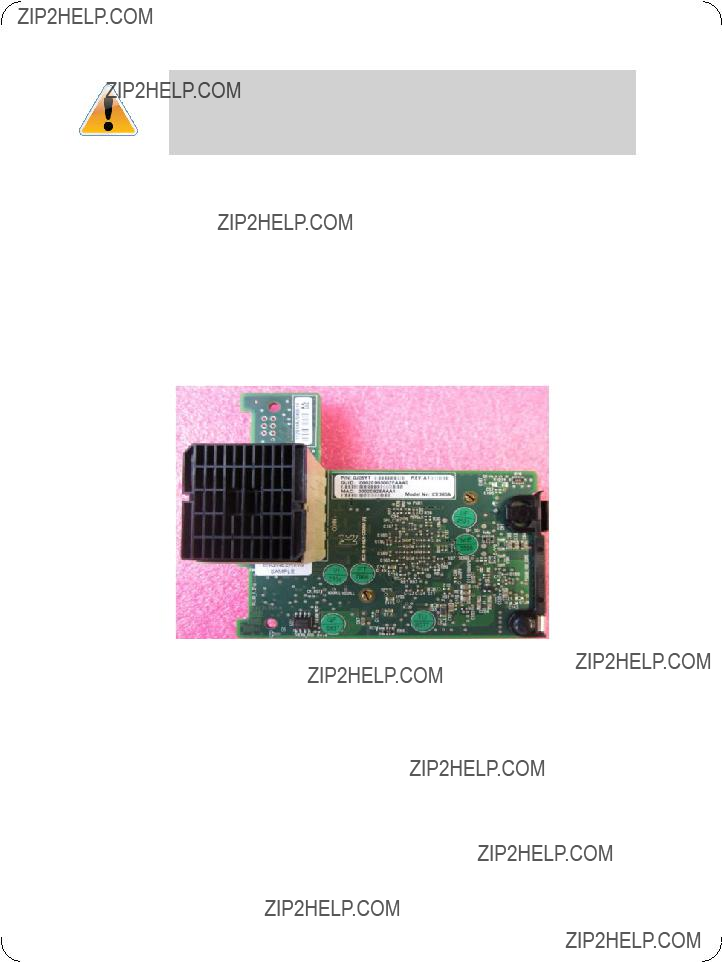
1.2Finding the GUID/MAC and Serial Number on the Mezzanine Cards
All cards include a label that has the card serial number and the card GUID for InfiniBand protocol on the print side of the card.

Figure 1: 0J05YT Label
Figure 2: Board Label
Figure 3: 0K6V3V Label
Figure 4: Board Label
2 Card Interfaces
2.1I/O Interfaces
Each mezzanine card includes the following interfaces:
???PCI Express (PCIe)
???
Figure 5: 0J05YT/0K6V3V Card
2.1.1InfiniBand Interface
The

2.1.2PCI Express Interface
The
2.1.3
A
Figure 6: I2C Connector
2.2Power
All adapter cards receive 12V and 3.3V power from the PCI Express connector. All other required power voltages are generated by
2.3Memory
The mezzanine cards support multiple memory devices through the PCI Express, SPI (Flash), and
2.3.1System Memory
The mezzanine cards utilize the PCI Express interface to store and access fabric connection infor- mation on the system memory.
2.3.2SPI
The mezzanine cards include one SPI Flash device accessible via the Flash interface of the Con-
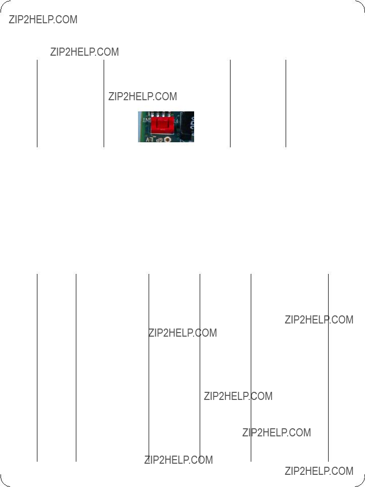
A jumper inserted into the drill on each adapter card indicates to the device whether an
Table 4 - Jumper Configuration
2.3.3EEPROM
The mezzanine cards incorporate an EEPROM that is accessible through the
Table 5 - 0J05YT VPD Layout

Table 5 - 0J05YT VPD Layout
Table 5 - 0J05YT VPD Layout

Table 6 - 0K6V3V VPD Layout

Table 6 - 0K6V3V VPD Layout

3 Card Installation
3.1Hardware RequirementsTBD
Before installing the mezzanine card, make sure that the system meets the hardware and software requirements listed in
Table 7 - Jumper Configuration
3.2Installation Kit
Make sure all of the parts are in the kit before you start the installation. If any parts are damaged or missing, call your supplier immediately.
Installation Instructions
Installation of this mezzanine card should only be done by a properly qualified technician or engi- neer. Installation or service not authorized by Dell or performed by unqualified personnel may void guarantees and warranties. Read and follow all safety precautions specified in this document and in the PowerEdge documentation.
Use the documentation supplied with the Dell Blade Servers to remove and replace the blade from the chassis.
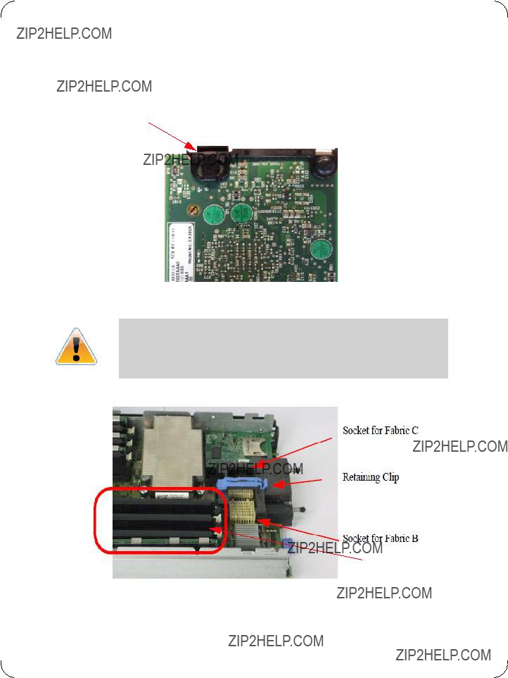
The card shown below has grounding clips that must come in contact with the chassis after the card is installed.
Figure 7: Grounding Clip
Make sure that you are properly grounded. Make sure that the equipment, both while in the chas- sis and while removed from the chassis, is properly grounded to prevent ESD.
Figure 8: Blade Server
DIMMS
DIMMS can be hot. Allow sufficient time for the blade components to cool before starting this procedure.
1.Remove the blade from the chassis.
2.Remove the cover from the blade.
3.Open the retaining clip.
The card can be placed in either of the two available slots.
4.Expose the socket to be used for the new card.
a.When replacing an existing card, remove the card from the socket. Grab the card on the edge on the side with UPC number and pull up while gently rocking the card back and forth.
b.For a new installation remove the protective cover enclosing the socket for the card.
Figure 9: Protective Cover in Place
Figure 10: Remove the Cover
Hold the mezzanine card by the edges only.
Line up the mezzanine card so that the pins of the mezzanine card are over the sockets in the blade server.
5.Plug the card into the socket by placing your thumb over the UPC symbol and pressing down until the card reaches the bottom.
Figure 11: Press on the Card
6.Close the retaining clip.
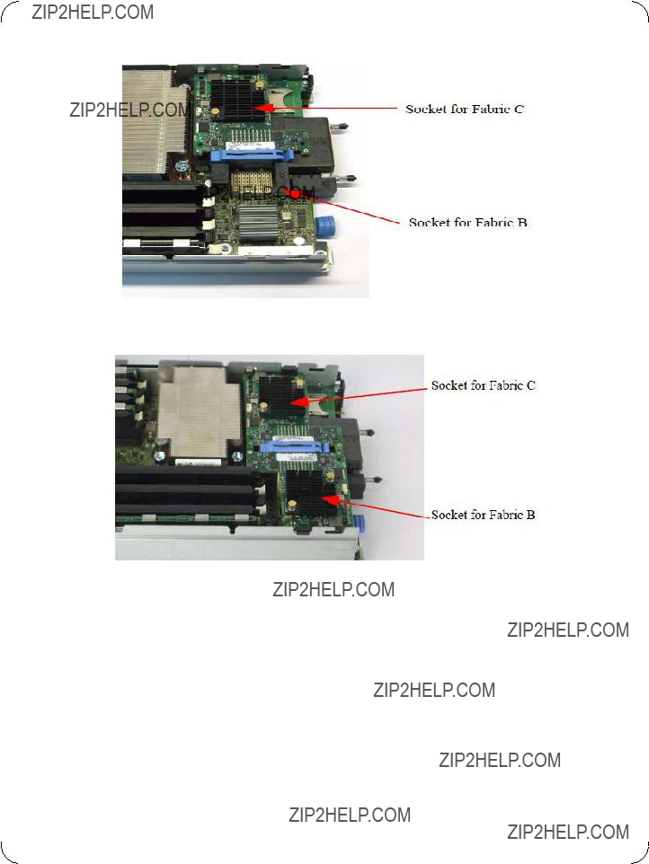
Figure 12: Single Card in Slot C
Figure 13: Two Cards Installed
7.Replace the blade server cover.
8.Replace the blade server into the chassis

3.3Safety Warnings
1.Installation Instructions
Read all installation instructions before connecting the equipment to the power source.
2. Over Temperature
This equipment should not be operated in an area with an ambient temperature exceeding the maximum recommended: ??C (??F).
To guarantee proper air flow, allow at least 8cm (3 inches) of clearance around the ventilation openings.
3. Lightening ??? Electrical Hazard
During periods of lightning activity, do not work on the equipment.
4. Installation of Equipment
This equipment should be installed, replaced, or serviced only by trained and qualified person- nel.
5. Disposal of Equipment =
Disposal of this equipment should be in accordance to all national laws and regulations.
6. Compliance with Local and National Codes
This equipment should be installed in compliance with local and national electrical codes.

4 Driver Software and Firmware
4.1Driver Software
4.1.1Linux
For Linux, download and install the latest OpenFabrics Enterprise Distribution (OFED) software package available via the Mellanox web site at: http://www.mellanox.com => Products => Soft- ware/Drivers => Infiniband & VPI Software/Drivers => Mellanox OFED => Download. Follow the installation instructions included in the download package (also available from the download page). To ensure that communication has been established follow the instructions below.
Check the link status
To check the IB link status, for IB cards, run ???ibstat??? and focus on the Physical state attributes. Example:
> Host# ibstat
LCA 'mlx4_0'
CA type: MT4099
Number of ports: 2
Firmware version: 2.10.2000
Hardware version: 0
Node GUID: 0x0002c903002fefe0
System image GUID: 0x0002c903002fefe3
Port 1:
State: Active
Physical state: LinkUp
Rate: 56
Base lid: 4
LMC: 0
SM lid: 12
Capability mask: 0x02514868
Port GUID: 0x0002c903002fefe1
Link layer: InfiniBand
Port 2:
State: Active
Physical state: LinkUp

Rate: 56
Base lid: 8
LMC: 0
SM lid: 12
Capability mask: 0x02514868
Port GUID: 0x0002c903002fefe2
Link layer: InfiniBand
Check the OFED version
To get the version of the running Mellanox OFED/BXOFED, run the following command:
# ofed_info |head
Troubleshooting MLNX_OFED Installation
For troubleshooting driver installation, please check Mellanox OFED driver user manual ar http://www.mellanox.com => Support => InfiniBand Products => Mellanox OFED.
4.1.2Windows
For Windows, download and install the latest Mellanox WinOF VPI for Windows software pack- age available via the Mellanox web site at: http://www.mellanox.com => Products => Software/ Drivers => Infiniband & VPI Software/Drivers => Mellanox WinOF VPI => Download. Follow the installation instructions included in the download package (also available from the download page). To ensure that communication has been established follow the instructions below.
Displaying the Device Manager will show the Mellanox adapter devices and an IPoIB (network) device for each port.

Figure 14: Device Manager (example)
Note: If the cards are connected to a managed switch, there is no need to run openSM. Only one OpenSM should run per subnet.In InfiniBand interfaces, OpenSM is installed as a disabled Windows service. To enable it, enter at the command line:
>sc start opensm
4.2FlexBoot
FlexBoot enables remote boot over Boot over InfiniBand (BoIB), or Boot over iSCSI
4.3Updating Mezzanine Card Firmware
Each card is shipped with the latest version of qualified firmware at the time of manufacturing. Firmware is updated occasionally, and the most recent firmware can be obtained from: http://www.mellanox.com => Support => Download Firmware. Check that the firmware on your card is the latest found on the Mellanox site, if not update to the latest version found on the Mella- nox web site.
Firmware can be updated on the stand alone single card using the flint tool of the Mellanox Firm- ware Tools (MFT) package. This package is available for download, along with its user manual, from the Mellanox Firmware Tools page. See http://www.mellanox.com => Support => Download Firmware Tools.
A firmware binaries table lists a binary file per mezzanine card. The file name of each such binary is composed by combining the firmware name, the firmware release version, and the card part

number. Please contact Mellanox System Support if you cannot find the firmware binary for your mezzanine card.
The following steps describe how to retrieve the PSID (firmware identification) and programmed firmware version of your mezzanine card. They also describe how to update the card with the lat- est firmware version available.
1.Retrieve the PSID and firmware version:
a.Install the MFT package. The package is available at www.mellanox.com => Products => Software/Drivers => InfiniBand & VPI Software/Drivers => Firmware Tools. Make sure to download the package corresponding to your computer???s operating system.
b.Enter: mst start
c.Get the Mellanox mst device name using the command "mst status". The mst device name will be of the form: /dev/mst/mt4099_pci_cr0
d.Get the PSID (firmware identification) and programmed firmware version using the command
2.Compare the programmed firmware version with the latest available.
a.Go to Mellanox???s web site: http://www.mellanox.com/supportdownloader. See Figure 15
b.Enter your card PSID to display the latest firmware
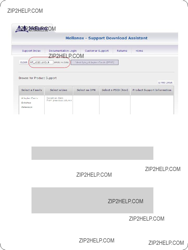
Figure 15: Support Download Assistant
3.If a newer firmware version exists for your mezzanine card, update the firmware as follows:
a.Download the firmware image zip file from the Download Center (see Step 2a above)
b.Unzip the firmware image
c.Burn the firmware image. Enter:
>flint
d.Reboot the computer
e.Enter: mst start
f.Verify that the card firmware was updated successfully
>flint

Appendix A: Specifications
A.1 Board Mechanical Drawing and Dimensions
The
All dimensions are in millimeters.
All the mechanical tolerances are +/- 0.1mm
Figure 16: Mechanical Drawing of 0J05YT/0K6V3V Mezzanine Card
23.92 

64.08
72.36 78.91
57.08
88

Rev 1.0
A.2 Specifications
Table 8 -
Appendix B: Avertissements de s??curit?? d???installation (French)
1. Instructions d???installation
Lisez toutes les instructions d???installation avant de brancher le mat??riel ?? la source d???alimentation ??lectrique.
2. Temp??rature excessive
Ce mat??riel ne doit pas fonctionner dans une zone avec une temp??rature ambi- ante d??passant le maximum recommand?? de 55??C (131??F). Un flux d???air de 200LFM ?? cette temp??rature ambiante maximale est n??cessaire. En outre, pour garantir un bon ??coulement de l???air, laissez au moins 8 cm (3 pouces) d???espace libre autour des ouvertures de ventilation.
3. Orages ??? dangers ??lectriques
Pendant un orage, il ne faut pas utiliser le mat??riel.
4. Installation du mat??riel
Ce mat??riel ne doit ??tre install??, remplac?? ou entretenu que par du personnel form?? et qualifi??.
5. Elimination du mat??riel
L?????limination de ce mat??riel doit s???effectuer dans le respect de toutes les l??gis- lations et r??glementations nationales en vigueur.
6. Codes ??lectriques locaux et nationaux
Ce mat??riel doit ??tre install?? dans le respect des codes ??lectriques locaux et nationaux.

Rev 1.0
Appendix C: Installation - Sicherheitshinweise (German)
1. Installationsanleitungen
Lesen Sie alle Installationsanleitungen, bevor Sie das Ger??t an die Stromvers- orgung anschlie??en.
2. ??bertemperatur
Dieses Ger??t sollte nicht in einem Bereich mit einer Umgebungstemperatur ??ber der maximal empfohlenen Temperatur von 55??C (131??F) betrieben werden. Au??erdem sollten mindestens 8 cm (3 in.) Freiraum um die Bel??f- tungs??ffnungen sein, um einen einwandfreien Luftstrom zu gew??hrleisten.
3. Bei Gewitter - Elektrische Gefahr
Arbeiten Sie w??hrend eines Gewitters und Blitzschlag nicht am Ger??t.
4.Ger??teinstallation
Diese Ger??t sollte nur von geschultem und qualifiziertem Personal installiert, ausgetauscht oder gewartet werden.
5. Ger??teentsorgung
Die Entsorgung dieses Ger??ts sollte unter Beachtung aller nationalen Gesetze
Bestimmungen erfolgen.
6. Regionale und nationale elektrische Bestimmungen
Dieses Ger??t sollte unter Beachtung der regionalen und nationalen elektrischen
Bestimmungen installiert werden.

Appendix D: Advertencias de seguridad para la instalaci??n (Warnings in Spanish)
1. Instrucciones de instalaci??n
Antes de conectar el equipo a la fuente de alimentaci??n, leer todas las instrucciones de instalaci??n.
2. Sobrecalentamiento
No se debe utilizar el equipo en un ??rea con una temperatura ambiente superior a la m??xima recomendada: 55??C(131??F). Adem??s, para garantizar una circulaci??n de aire adecuada, se debe dejar como m??nimo un espacio de 8 cm (3 pulgadas) alrededor de las aberturas de ventilaci??n.
3. Cuando hay rayos: peligro de descarga el??ctrica
No utilizar el equipo ni conectar o desconectar cables durante per??odos de actividad de rayos.
4. Instalaci??n de equipos
La instalaci??n, el reemplazo y el mantenimiento de este equipo estar??n a cargo ??nica- mente de personal capacitado y competente.
5. Eliminaci??n de equipos
La eliminaci??n definitiva de este equipo se debe efectuar conforme a todas las leyes y reglamentaciones nacionales.
6. C??digos el??ctricos locales y nacionales
Este equipo se debe instalar conforme a los c??digos el??ctricos locales y nacionales.