Dell PowerEdge 11th
Generation Servers: R810,
R910, and M910 Memory
Guidance
A Dell Technical White Paper
Dell ???Product Group
Armando Acosta and James Pledge
Dell PowerEdge 11th
Generation Servers: R810,
R910, and M910 Memory
Guidance
A Dell Technical White Paper
Dell ???Product Group
Armando Acosta and James Pledge
PowerEdge 11th Generation Servers: R810, R910, and M910 Memory Guidance
THIS WHITE PAPER IS FOR INFORMATIONAL PURPOSES ONLY, AND MAY CONTAIN TYPOGRAPHICAL
ERRORS AND TECHNICAL INACCURACIES. THE CONTENT IS PROVIDED AS IS, WITHOUT EXPRESS OR
IMPLIED WARRANTIES OF ANY KIND.
?? 2010 Dell Inc. All rights reserved. Reproduction of this material in any manner whatsoever without the express written permission of Dell Inc. is strictly forbidden. For more information, contact Dell.
Dell, the DELL logo, and PowerEdge are trademarks of Dell Inc. Intel and Xeon are registered trademarks of Intel Corporation in the U.S. and other countries. Other trademarks and trade names may be used in this document to refer to either the entities claiming the marks and names or their products. Dell Inc. disclaims any proprietary interest in trademarks and trade names other than its own.
March 2010
Page ii
PowerEdge 11th Generation Servers: R810, R910, and M910 Memory Guidance
Introduction
This paper serves as memory guidance for Dell??? 11th Generation PowerEdge??? R810, R910, and M910 servers released March 2010 using the new Intel?? Xeon?? 7500 and 6500 series processors that support DDR3 memory technology. This document explains what Dell supports and describes rules for installing memory. Examples of terminology definitions and details about performance or Reliability, Availability, and Serviceability (RAS) features are shown as follows.
Quick Reference Guide (Terminology Definitions)
DDR3 (Double Data Rate): The latest (3rd) generation of DDR DRAM; replaces DDR and DDR2 memory.
DIMM: Dual Inline Memory Module. This is the memory stick that is installed in each memory slot. It is comprised of multiple memory chips and, in some cases, registers, buffers and/or temperature sensors.
Dual Rank (DR): Two rows of DRAM comprising 64 bits of data each.
ECC (Error Checking and Correcting): This memory coding method is able to correct and identify certain types of DRAM and interface errors.
Enhanced ECC: Like ECC, but this memory coding method protects against additional memory error types including control line errors.
Hemisphere Mode: This mode allows interleaving between a processor???s two memory controllers leading to improved performance. Interleaving also adds benefits to memory thermal performance by spreading memory accesses across multiple DIMMs and reducing memory ???hot spots.???
MC: Memory Controller
Intel 7500 Scalable Memory Buffer: Translates one Scalable Memory Interconnect (SMI) bus into two DDR3 buses. Intel Xeon 7500 and 6500 series processors must have this device to operate.
Mirror Mode (Mirroring): Two memory controllers are configured to allow the same data to be written to each. Each controller???s data is identical to the other; thus, if one fails or has multiple bit errors, there is a backup. The operating system will report half of your installed memory.
Quad Rank (QR): Four rows of DRAM comprising 64 bits of data each.
Rank: A row of DRAM devices comprising 64 bits of data per DIMM.
RAS: Reliability, Availability, and Serviceability
SDDC: Single Device Data Correction. Memory systems that utilize Single Device Data Correction can detect and correct multiple bit errors that come from a single memory chip on the DIMM.
Single Rank (SR): One row of DRAM comprising 64 bits of data.
Page 2
PowerEdge 11th Generation Servers: R810, R910, and M910 Memory Guidance
Sparing (DIMM and Rank): The system allocates a Rank or DIMM per channel as a Spare memory region, and is able to move a Rank or DIMM exhibiting correctable errors to the Spare while the operating system is running.
RDIMM: Registered DIMMs. Address, Control, and Clock lines are buffered and
Overview Intel Architecture
PowerEdge 11Th Generation
It is important to recognize that memory speed and the processor chosen have interdependencies. The processor???s maximum QuickPath Interconnect (QPI) speed will determine the memory performance (1066 MTS, 978 MTS, or 800 MTs). Memory speed remains locked regardless of DIMM population. There is no speed change when populating increasing numbers of DIMMs. However, there are recommended population practices when upgrading or changing memory. DIMMs always must be populated identically in pairs
Note: Only RDIMMS are supported with Intel 7500 and 6500 series processors.
Page 3
PowerEdge 11th Generation Servers: R810, R910, and M910 Memory Guidance
PowerEdge R810 and M910
The R810 and M910 servers utilize DDR3 memory providing a high performance,
The R810 and M910 utilize Intel Xeon 7500 and 6500 series processors that have four SMI channels for each socket. Each of those memory controllers then has two SMI channels that connect to the Intel 7500 Scalable Memory Buffer.
The DDR3 memory interface consists of eight Intel 7500 Scalable Memory Buffers (two per socket), each of which has two DDR3 memory channels. Each channel supports up to two RDIMMs for single/dual/quad rank. By limiting to two DIMMs per DDR channel, the system can support
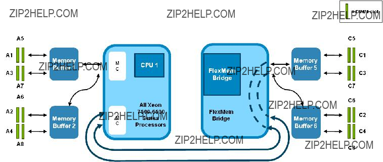
FlexMem Bridge Technology
In a
To overcome this limitation with two CPUs, the R810 and M910 use a
The FlexMem Bridge provides the following:
???Two
???One
???The
???CPU 1 will have access to DIMMs
???CPU 2 will have access to DIMMs
Page 4
PowerEdge 11th Generation Servers: R810, R910, and M910 Memory Guidance
Figure 1. FlexMem Bridge Illustration
Page 5

PowerEdge 11th Generation Servers: R810, R910, and M910 Memory Guidance
Figure 2. R810 and M910 Series Servers Memory Illustration
Note: This illustration is not a technical schematic of a motherboard. DIMMs
PowerEdge R910
The R910 utilizes DDR3 memory providing a high performance,
The R910 utilizes Intel Xeon 7500 series processors that have one memory controller hub and two integrated memory controllers. Each of those memory controllers has two SMI channels that connect to the Intel 7500 Scalable Memory Buffer.
The DDR3 memory interface consists of 16 Intel 7500 Scalable Memory Buffers, each of which has two DDR3 memory channels. Each channel supports up to two RDIMMs
Page 6

PowerEdge 11th Generation Servers: R810, R910, and M910 Memory Guidance
The R910 has eight memory risers; each memory riser has two Millbrook memory buffers and eight DIMM slots.
Figure 3. R910 Series Servers Memory Illustration
Note: This illustration is not a technical schematic of a motherboard. DIMMs in Risers A and B correspond to CPU 1, DIMMs in Risers C and D correspond to CPU 2, DIMMs in Risers E and F correspond to CPU 3, and DIMMs in Risers G and H correspond to CPU 4. A CPU must be present to populate the riser. A system can operate with only one riser per CPU.
Optimizing Memory Performance for Intel Xeon 7500 and 6500 Series Processors
Intel Xeon 7500 and 6500 Series processors support a maximum memory performance of 1066 MTs.
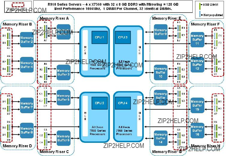
Best Performance
2 DIMMS per Memory Buffer Channel, all memory controllers populated equally with 64 DIMMs and 8 Memory Risers (R910) (see Figure 4) or 32 identical DIMMs (R810, M910) (see Figure 5), highest bandwidth and lowest latency
Better Performance
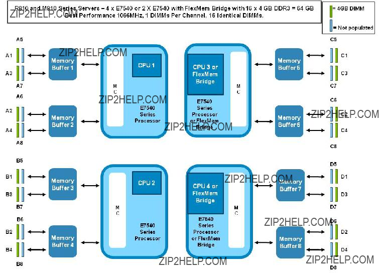
1 DIMM per Memory Buffer Channel, all memory controllers populated equally with 32 DIMMs and 8 Memory Risers (R910) (see Figure 6) or 16 identical DIMMS (R810, M910) (see Figure 7), slight bandwidth decrease
Page 7
PowerEdge 11th Generation Servers: R810, R910, and M910 Memory Guidance
Good Performance
2 DIMMS per Memory Buffer Channel, all memory controllers populated equally with 32 DIMMs and 4 Memory Risers (R910), lower maximum bandwidth, higher latency
1 DIMM per Memory Buffer Channel, all memory controllers populated equally with 16 DIMMs and 4 Memory Risers (R910), lower maximum bandwidth, higher latency
Note: Mixed DIMM capacity is supported. The recommendation is to populate memory controllers equally and always pair DIMMs identically.
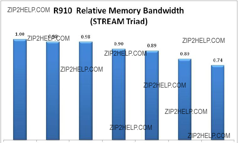
Figure 4. R910 Relative Memory Bandwidth for the Intel Xeon 7500 Series Processors
Page 8
PowerEdge 11th Generation Servers: R810, R910, and M910 Memory Guidance
Figure 5. M910/R810 Relative Memory Bandwidth for the Intel Xeon 6500 and 7500 Series Processors
Page 9

PowerEdge 11th Generation Servers: R810, R910, and M910 Memory Guidance
Figure 6. R910 With 64 Identical DIMMs, 2 DIMMs Per Channel
Page 10
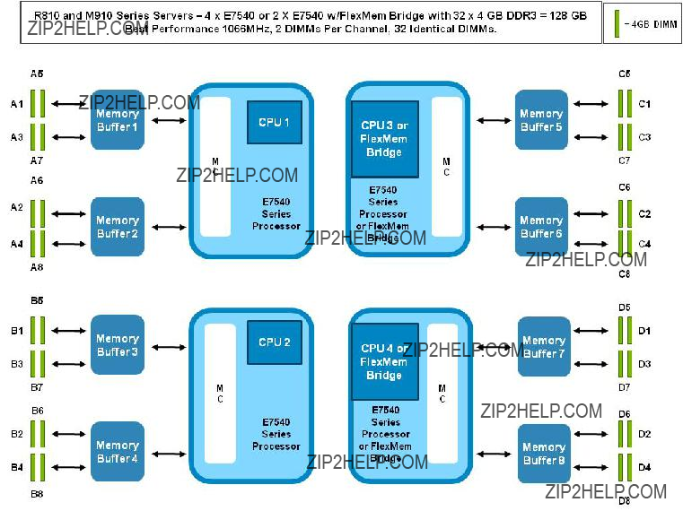
PowerEdge 11th Generation Servers: R810, R910, and M910 Memory Guidance
Figure 7. R810 or M910 With 32 Identical DIMMs, 2 DIMMs Per Channel
Page 11

PowerEdge 11th Generation Servers: R810, R910, and M910 Memory Guidance
Figure 8. R910 With 32 Identical DIMMs, 1 DIMM Per Channel
Page 12
PowerEdge 11th Generation Servers: R810, R910, and M910 Memory Guidance
Figure 9. R810 and M910 With 16 Identical DIMMs, 1 DIMM Per Channel
Memory RAS Features
Sparing
For Rank sparing, one rank on each
For Dual rank DIMMs: 1 rank within a DIMM is used as a spare
For Quad rank DIMMs: 1 or 2 ranks within a DIMM are used as a spare
Page 13

PowerEdge 11th Generation Servers: R810, R910, and M910 Memory Guidance
Figure 10. Example of Sparing for Dual Rank and Quad Rank DIMMs
Mirroring
For mirroring, the R910 will support 2P/4P configurations for >= 64 GB only. The R810 and M910 support mirroring in 32 DIMM configurations >= 64 GB only. When mirroring is enabled, only half of the physical memory will be visible to the system. A full copy of the memory is maintained, and, in the event of an uncorrectable error, the system will switch over to the mirrored copy. The R910 uses
Page 14
PowerEdge 11th Generation Servers: R810, R910, and M910 Memory Guidance
Figure 11. Example of R910
Note: A1, A3 are mirrored to A2, A4; B1, B3 are mirrored to B2, B4; C1, C3 are mirrored to C2, C4; D1, D3 are mirrored to D2, D4; E1, E3 are mirrored to E2, E4; F1, F3 are mirrored to F2, F4; G1, G3 are mirrored to G2, G4; H1, H3 are mirrored to H2, H4.
For mirroring, the R810 will support 2P/4P configurations with 32 DIMMs only. When mirroring is enabled, only half of the physical memory will be visible to the system software. A full copy of the memory is maintained, and, in the event of an uncorrectable error, the system will switch over to the mirrored copy. In 2P mode, the mirroring will be
Page 15

PowerEdge 11th Generation Servers: R810, R910, and M910 Memory Guidance
Figure 12. Example of R810 and M910
For 4P, the R810 will also support mirroring in the
Page 16

PowerEdge 11th Generation Servers: R810, R910, and M910 Memory Guidance
Figure 13. Example of R810 and M910
Note: * X7550 will not be offered on the R810 or M910. The R810 and M910 will support only two 130 Watt processors. **E7530 will not be offered on the R810 or M910. ***All 6500 series processors are only
Page 17