Dell PowerEdge FC430
Owner's Manual
Regulatory Model: E01B Series
Regulatory Type: E01B002
Dell PowerEdge FC430
Owner's Manual
Regulatory Model: E01B Series
Regulatory Type: E01B002

Notes, Cautions, and Warnings
NOTE: A NOTE indicates important information that helps you make better use of your computer.
CAUTION: A CAUTION indicates either potential damage to hardware or loss of data and tells you how to avoid the problem.
WARNING: A WARNING indicates a potential for property damage, personal injury, or death.
Copyright ?? 2015 Dell Inc. All rights reserved. This product is protected by U.S. and international copyright and intellectual property laws. Dell??? and the Dell logo are trademarks of Dell Inc. in the United States and/or other jurisdictions. All other marks and names mentioned herein may be trademarks of their respective companies.
2015 - 04
Rev. A00
3
4
5
6

1
About your Dell PowerEdge FC430
The Dell PowerEdge FC430 is a quarter width sled that supports up to two processors based on the Intel Haswell EP product family, up to eight DIMMs, and up to two 1.8??? uSATA Solid State Drives (SSD).
The PowerEdge FC430 system is available in the following configurations:
???A single 1.8 inch SSD drive bay.
???A dual 1.8 inch SSD drive bay.
Front panel features and indicators
Figure 1. Front panel features and indicators??? dual SSD system
7
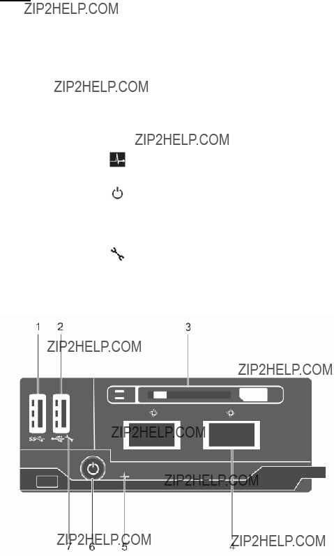
Figure 2. Front panel features and indicators??? single SSD system
8

SSD activity indicator codes
The Solid State Drive (SSD) indicators display different patterns as drive events occur in the system.
NOTE: The sled must have an SSD or an SSD blank installed in each drive bay.
9

Figure 3. SSD indicators
NOTE: If the drive is in theAdvanced Host Controller Interface (AHCI) mode, the status LED (on the right side) does not function and remains OFF.
Blinks green, amber, and then turns off
Blinks amber four times per second
Blinks green slowly
Steady green
Blinks green for three seconds, amber for three seconds, and switches off for six seconds
NOTE: The drive status indicator remains OFF until all drives are initialized after system power is applied. Drives are not ready for insertion or removal during this time.
Drive predicted failure
Drive failed
Drive rebuilding
Drive online
Rebuild aborted
iDRAC Direct LED indicator codes
NOTE: The iDRAC Direct LED indicator does not light up in the USB mode.
10
Figure 4. iDRAC Direct LED indicator
1.iDRAC Direct status indicator
The table below displays iDRAC Direct LED indicator activity when configuring iDRAC Direct by using the management port (USB XML Import).
The table below displays iDRAC Direct LED indicator activity when configuring iDRAC Direct using your laptop and cable (Laptop Connect).
11

Documentation matrix
The documentation matrix provides information about documents that you can refer to, for setting up and managing your system.
Get an overview of the Dell Systems Management offerings
Configure and log in to iDRAC, set up managed and management system, know the iDRAC features, and troubleshoot using iDRAC
Dell OpenManage Systems Management Overview Guide at dell.com/openmanagemanuals
Integrated Dell Remote Access Controller User's Guide at dell.com/esmmanuals
Know about the RACADM subcommands and supported RACADM interfaces
Start, enable, and disable Lifecycle Controller, know the features, use, and troubleshoot Lifecycle Controller
RACADM Command Line Reference Guide for iDRAC and CMC at dell.com/esmmanuals
Dell Lifecycle Controller User???s Guide at dell.com/ esmmanuals
Know the enclosure features, remove and install enclosure components, and troubleshoot enclosure components
Enclosure Owner???s Manual at dell.com/ poweredgemanuals
Know the features of the storage controller cards, deploy the cards, and manage the storage subsystem
Storage controller documentation at dell.com/ storagecontrollermanuals
See the event and error messages generated by the system firmware and agents that monitor system components
Dell Event and Error Messages Reference Guide at dell.com/esmmanuals
12

Quick Resource Locator
Use the Quick Resource Locator (QRL) to get immediate access to system information and
13

2
Performing initial system configuration
After you receive your PowerEdge system, you must set up your system in the enclosure, install the operating system if it is not
Setting up your system
1.Unpack the sled.
2.Remove the I/O connector cover from the sled connectors.
CAUTION: While installing the sled, ensure that it is properly aligned with the slot on the enclosure to prevent damage to the sled connectors.
3.Install the sled in the enclosure.
4.Turn on the enclosure.
 NOTE: Wait for the chassis to initialize before you press the power button.
5.Turn on the sled by pressing the power button on the sled. Alternatively, you can also turn on the sled by using:
???The sled iDRAC. For more information, see Logging in to iDRAC.
???The enclosure Chassis Management Controller (CMC), after the sled iDRAC is configured on the CMC. For more information, see the CMC User???s Guide at dell.com/esmmanuals.
Setting up and configuring the iDRAC IP address
You can set up the iDRAC IP address using one of the following interfaces:
???iDRAC Settings utility
???Dell Lifecycle Controller
???Dell Deployment Toolkit
???CMC Web interface
You can configure iDRAC using one of the following interfaces:
???iDRAC Web interface
???RACADM
???Remote services
???IPMI tool
For more information on setting up and configuring iDRAC, see the iDRAC User???s Guide at dell.com/ esmmanuals.
14

Logging in to iDRAC
You can log in to iDRAC as an iDRAC user, a Microsoft Active Directory user, or a Lightweight Directory Access Protocol (LDAP) user. You can also log in using Single
You can also access iDRAC using RACADM. For more information, see the RACADM Reference Guide for iDRAC and CMC available at dell.com/esmmanuals.
Installing the operating system
You can install the supported operating system on the sled by using the following methods:
???Dell Systems Management Tools and Documentation media. See the operating system documentation at dell.com/operatingsystemmanuals.
???Dell Lifecycle Controller. See the Lifecycle Controller documentation at dell.com/esmmanuals.
???Dell OpenManage Deployment Toolkit. See the OpenManage documentation at dell.com/ openmanagemanuals.
For information on the list of operating systems supported on your system, see the operating system???s support matrix at dell.com/ossupport.
Managing your system remotely
To perform
You can also remotely monitor and manage the sleds from a single workstation, using the Dell OpenManage Server Administrator (OMSA) software and OpenManage Essentials (OME) systems management console. For more information, see dell.com/openmanagemanuals.
Downloading drivers and firmware
It is recommended that you download and install the latest BIOS, drivers, and systems management firmware on your system.
Prerequisites
Ensure that you clear the web browser cache.
Steps
1.Go to dell.com/support/drivers.
2.In the Product Selection section, enter the Service Tag of your system in the Service Tag or Express Service Code field.
NOTE: If you do not have the Service Tag, select Automatically detect my Service Tag for me to allow the system to automatically detect your Service Tag, or select Choose from a list of all Dell products to select your product from the Product Selection page.
3.Click Get drivers and downloads.
15
The drivers that are applicable to your selection are displayed.
4.Download the drivers you require to a diskette drive, USB drive, CD, or DVD.
16

3
The
Your PowerEdge system has the following
???System Setup
???Boot Manager
???Dell Lifecycle Controller
Navigation keys
The navigation keys can help you quickly access the
About System Setup
Using System Setup, you can configure the BIOS settings, iDRAC settings, and device settings of your system.
You can access System Setup in two ways:
17

???Standard Graphical Browser ??? This is enabled by default.
???Text Browser ??? This is enabled by using Console Redirection.
NOTE: By default, help text for the selected field is displayed in the graphical browser. To view the help text in the text browser, press <F1>.
About Dell Lifecycle Controller
Dell Lifecycle Controller allows you to perform tasks such as configuring BIOS and hardware settings, deploying an operating system, updating drivers, changing RAID settings, and saving hardware profiles. For more information about Dell Lifecycle Controller, see the documentation at dell.com/esmmanuals.
Entering System Setup
1.Turn on or restart your system.
2.Press <F2> immediately after you see the following message:
<F2> = System Setup
If your operating system begins to load before you press <F2>, wait for the system to finish booting, and then restart your system and try again.
Enabling Console Redirection
To enable Console Redirection, in System Setup, select System BIOS ??? Serial Communication ??? On with Console Redirection via COMx (or Auto if a serial terminal is present).
System Setup Main Menu
System BIOS screen
By using the System BIOS screen, you can view the BIOS settings as well as edit specific functions such as Boot Order, System Password, Setup Password, setting the RAID mode, and enabling or disabling USB ports.
To view the System BIOS screen click System BIOS on the System Setup Main Menu. The System BIOS screen details are explained as follows:
18

System Information screen
You can use the System Information screen to view system properties such as Service Tag, system model, and the BIOS version.
To view the System Information click System Setup Main Menu ??? System BIOS ??? System Information.
The System Information screen details are explained as follows:
19

System Memory screen
TheSystem Memory screen allows you to view all the memory settings as well as enable or disable specific memory functions such as system memory testing and node interleaving.
In the System Setup Main Menu, click System BIOS ??? System Memory.
Processor Settings screen
You can use the Processor Settings screen to view the processor settings and perform specific functions such as enabling virtualization technology, hardware prefetcher, and logical processor idling.
To view the Processor Settings screen click the System Setup Main Menu ??? System BIOS ??? Processor Settings.
20
21

SATA Settings screen
You can use the SATA Settings screen to view the SATA settings of SATA devices and enable RAID on your system.
To view the SATA Settings screen, click System Setup Main Menu ??? System BIOS ??? SATA Settings.
Boot Settings screen
You can use the Boot Settings screen to set the Boot mode to either BIOS or UEFI. It also enables you to specify the boot order.
To view the Boot Settings screen, click System Setup Main Menu ??? System BIOS ??? Boot Settings.
22

Network Settings screen
You can use the Network Settings screen to modify PXE device settings. Network Settings are only available in UEFI boot mode. BIOS does not control network settings in the BIOS boot mode. For BIOS boot mode, the network settings are handled by the network controllers option ROM.
To view the Network Settings screen, click System Setup Main Menu ??? System BIOS ??? Network Settings.
PXE Device n Settings (n = 1 Allows you to control the configuration of the PXE device. to 4)
Integrated Devices screen
Integrated Devices screen allows you to view and configure the settings of all integrated devices including the video controller, integrated RAID controller, and the USB ports.
To view the Integrated Devices screen, click the System Setup Main Menu, ??? System BIOS ??? Integrated Devices.
23

Serial Communication screen
You can use the Serial Communication screen to view the properties of the serial communication port. To view the Serial Communication screen, click System Setup Main Menu ??? System BIOS ??? Serial Communication.
24

System Profile Settings screen
You can use the System Profile Settings screen to enable specific system performance settings such as power management.
To view the System Profile Settings click System Setup Main Menu ??? System BIOS ??? System Profile Settings.
25

Number of Turbo Boot Enabled Cores for Processor 1
Monitor/Mwait
NOTE: If there are two processors installed in the system, you see an entry for Number of Turbo Boost Enabled Cores for Processor 2.
Controls the number of turbo boost enabled cores for processor 1. By default, the maximum number of cores is enabled.
Enables the Monitor/Mwait instructions in the processor. By default, the Monitor/Mwait option is set to Enabled for all system profiles, except
Custom.
NOTE: This option can be disabled only if the C States option in
Custom mode is set to disabled.
NOTE: When C States set to Enabled in Custom mode, changing the Monitor/Mwait setting does not impact system power/ performance.
System Security Settings screen
The System Security screen allows you to perform specific functions such as setting the system password, setup password, and disabling the power button.
To view the System Security Settings in the System Setup Main Menu screen, click System BIOS ??? System Security Settings.
Setup Password
Password Status
TPM Security
Allows you to set the setup password. This option is
Allows you to lock the system password. By default, the Password Status option is set to Unlocked.
NOTE: The TPM menu is available only when the TPM module is installed.
26

Secure Boot Custom Policy Settings screen
Secure Boot Custom Policy Settings is displayed only when Secure Boot Policy is set to Custom.
In the System Setup Main Menu, click System BIOS ??? System Security ??? Secure Boot Custom Policy Settings.
Key Exchange Key Database Allows you to import, export, delete, or restore entries in the Key Exchange Key (KEK) Database
27

Miscellaneous Settings screen
You can use the Miscellaneous Settings screen to perform specific functions such as updating the asset tag, and changing the system date and time.
To view the Miscellaneous Settings screen, click System Setup Main Menu ??? System BIOS ??? Miscellaneous Settings.
28

About Boot Manager
Boot Manager enables you to add, delete, and arrange boot options. You can also access System Setup and boot options without restarting the system.
Entering Boot Manager
The Boot Manager screen enables you to select boot options and diagnostic utilities.
1.Turn on or restart your system.
2. Press F11 when you see the message F11 = Boot Manager.
If your operating system begins to load before you press F11, allow the system to finish booting, and then restart your system and try again.
Boot Manager main menu
Changing the boot order
You may have to change the boot order if you want to boot from a USB key or an optical drive. The instructions given below may vary if you have selected BIOS for Boot Mode.
1.In the System Setup Main Menu, click System BIOS ??? Boot Settings.
2.Click Boot Option Settings ??? Boot Sequence.
3.Use the arrow keys to select a boot device, and use the <+> and
4.Click Exit, click Yes to save the settings on exit.
29

Choosing the system boot mode
System Setup enables you to specify the boot mode for installing your operating system:
???BIOS boot mode (the default) is the standard
???Unified Extensible Firmware Interface (UEFI) boot mode is an enhanced
To select the system Boot Mode:
1.In System Setup click Boot Settings and select Boot Mode.
2.Select the boot mode you want the system to boot into.
NOTE: After the system boots in the specified boot mode, proceed to install your operating system from that mode.
CAUTION: Trying to boot the operating system from the other boot mode will cause the system to halt at startup.
NOTE: Operating systems must be
NOTE: For the latest information on supported operating systems, go to dell.com/ossupport.
Assigning a system or setup password
Prerequisites
NOTE: The password jumper enables or disables the System Password and Setup Password features. For more information on the password jumper settings, see ???System board jumper settings???.
You can assign a new System Password or Setup Password or change an existing System Password or
Setup Password only when the password jumper setting is enabled and Password Status is set to Unlocked. If the Password Status is set to Locked, you cannot change the System Password or Setup Password.
If the password jumper setting is disabled, the existing System Password and Setup Password is deleted and you need not provide the system password to boot the system.
Steps
1.To enter System Setup, press F2 immediately after a
2.In the System Setup Main Menu, select System BIOS and press Enter. The System BIOS screen is displayed.
3.In the System BIOS screen, select System Security and press Enter. The System Security screen is displayed.
4.In the System Security screen, verify that Password Status is Unlocked.
5.Select System Password, enter your system password, and press Enter or Tab. Use the following guidelines to assign the system password:
??? A password can have up to 32 characters.
30
???The password can contain the numbers 0 through 9.
???Only the following special characters are allowed: space, (???), (+), (,),
A message prompts you to
6.
7.Select Setup Password, enter your system password and press Enter or Tab. A message prompts you to
8.
9.Press Esc to return to the System BIOS screen. Press Esc again, and a message prompts you to save the changes.
 NOTE: Password protection does not take effect until the system reboots.
Using your system password to secure your system
Prerequisites
NOTE: If you have assigned a setup password, the system accepts your setup password as an alternate system password.
Steps
1.Turn on or reboot your system.
2.Type your password and press Enter.
Next steps
When Password Status is Locked, type the password and press Enter when prompted at reboot.
If an incorrect system password is entered, the system displays a message and prompts you to
Even after you shut down and restart the system, the error message is displayed until the correct password is entered.
NOTE: You can use the Password Status option in conjunction with the System Password and Setup Password options to protect your system from unauthorized changes.
Deleting or changing an existing system password or setup password
Prerequisites
Ensure that the Password jumper is set to enabled and the Password Status is set to Unlocked before attempting to delete or change the existing System password or Setup password. You cannot delete or change an existing System password or Setup password if the Password Status is set to Locked.
Steps
1.To enter System Setup, press F2 immediately after a
2.In System Setup Main Menu, select System BIOS and press Enter. The System BIOS screen is displayed.
3.In theSystem BIOS screen, select System Security and press Enter. The System Security screen is displayed.
31

4.In the System Security screen, verify that Password Status is set to Unlocked.
5.Select System Password, change or delete the existing system password and press Enter or Tab.
6.Select Setup Password, change or delete the existing setup password and press Enter or Tab.
NOTE: If you change the System password or Setup password, a message prompts you to re- enter the new password. If you delete the System password or Setup password, a message prompts you to confirm the deletion.
7.Press Esc to return to the System BIOS screen. Press Esc again, and a message prompts you to save the changes and exit.
Operating with a setup password enabled
If Setup Password is set to Enabled, enter the correct setup password before modifying most of the System Setup options.
If you do not enter the correct password in three attempts, the system displays the message
Incorrect Password! Number of unsuccessful password attempts: <x> System Halted! Must power down.
Even after you shut down and restart the system, the error message is displayed until the correct password is entered. The following options are exceptions:
???If System Password is not set to Enabled and is not locked through the Password Status option, you can assign a system password.
???You cannot disable or change an existing system password.
NOTE: You can use the Password Status option in conjunction with the Setup Password option to protect the system password from unauthorized changes.
Embedded systems management
The Dell Lifecycle Controller provides advanced embedded systems management throughout the server???s lifecycle. The Lifecycle Controller can be started during the boot sequence and can function independently of the operating system.
NOTE: Certain platform configurations may not support the full set of features provided by the Lifecycle Controller.
For more information about setting up the Lifecycle Controller, configuring hardware and firmware, and deploying the operating system, see the Lifecycle Controller documentation at dell.com/support/home.
iDRAC Settings utility
The iDRAC Settings utility is an interface to set up and configure the iDRAC parameters using UEFI. You can enable or disable various iDRAC parameters using the iDRAC Settings utility, for example:
???Configure, enable, or disable the iDRAC local area network through the dedicated iDRAC Enterprise card port or the embedded NIC
???Enable or disable IPMI over LAN
???Enable a LAN Platform Event Trap (PET) destination
???Attach or detach the Virtual Media devices
For more information on using iDRAC, see the iDRAC User's Guide, at dell.com/esmmanuals.
32
Entering the iDRAC Settings utility
1.Turn on or restart the managed system.
2.Press <F2> during
3.In the System Setup Main Menu page, click iDRAC Settings.
The iDRAC Settings page is displayed.
33

4
Installing and removing sled components
This section provides information on installing and removing the sled components. For information on installing and removing the enclosure components, see the enclosure Owner's Manual at dell.com/ poweredgemanuals.
Customer and field replaceable units
The following components are Customer Replaceable Units (CRUs):
???Cooling shroud
???PCIe mezzanine card
???Internal SD card
???SD vFlash card
???LAN on Motherboard riser card (LOM)
???System Memory
???Solid State Drive (SSD)
???SSD carrier
???SSD blank
???SSD backplane
???NVRAM backup battery
???
???Internal Dual SD Module card
The following components are Field Replaceable Units (FRUs). Removal and installation procedures should be performed only by Dell certified service technicians.
???Heatsink
???Processors
???System board
Safety instructions
CAUTION: Many repairs may only be done by a certified service technician. You should only perform troubleshooting and simple repairs as authorized in your product documentation, or as directed by the online or telephone service and support team. Damage due to servicing that is not authorized by Dell is not covered by your warranty. Read and follow the safety instructions that came with the product.
NOTE: It is recommended that you always use a static mat and static strap while working on components inside the system.
34

NOTE: To ensure proper operation and cooling, all bays in the system must be populated at all times with either a system component or with a blank.
Before working inside your system
1.Turn off the sled using the CMC.
2.Remove the sled from the enclosure.
3.Install the I/O connector cover.
After working inside your system
1.Install the sled in the enclosure.
2.Turn on the sled.
Recommended tools
You need the following items to perform the procedures in this section:
???#1 and #2 Phillips screwdrivers
???4 mm and 5 mm Hex nut drivers
???Wrist grounding strap
Removing and installing a sled
CAUTION: Many repairs may only be done by a certified service technician. You should only perform troubleshooting and simple repairs as authorized in your product documentation, or as directed by the online or telephone service and support team. Damage due to servicing that is not authorized by Dell is not covered by your warranty. Read and follow the safety instructions that came with the product.
Removing a sled
Prerequisites
1.Ensure that you read the Safety instructions.
2.Follow the procedure listed in Before working inside your system.
Steps
1.Turn off the sled.
 NOTE: When a sled is turned off, the
2.Press the release button on the sled handle and rotate the sled handle away from the sled to disengage the sled from the interposer connectors.
3.Slide the sled out of the enclosure.
CAUTION: If you are permanently removing the sled, install a sled blank. Operating the system for extended periods of time without a sled blank installed can cause the enclosure to overheat.
35

NOTE: For more information on the interposer connections, refer to the Dell PowerEdge FX2 and FX2s Enclosure Owner???s Manual at dell.com/poweredgemanuals.
Next steps
1.Follow the procedure listed in After working inside your system.
Installing a sled
1.Press the release button on the sled handle to the open position.
2.Align the sled with the bay on the enclosure.
3.Slide the sled into the enclosure until the sled connectors are firmly engaged with the interposer connectors.
The sled handle rotates toward the enclosure as the sled slides into the enclosure.
4.Press the sled handle to closed position until the release button clicks into place.
5.Turn on the sled.
36

Inside the sled
13.SSD backplane
Cooling shroud
Your system includes a cooling shroud that ensures optimum airflow over the memory modules and processor(s). You can remove and install the cooling shroud.
Removing the cooling shroud
Prerequisites
CAUTION: Many repairs may only be done by a certified service technician. You should only perform troubleshooting and simple repairs as authorized in your product documentation, or as directed by the online or telephone service and support team. Damage due to servicing that is not authorized by Dell is not covered by your warranty. Read and follow the safety instructions that came with the product.
CAUTION: Never operate your system with the cooling shroud removed. The system may get overheated quickly, resulting in shutdown and loss of data.
1.Ensure that you read the Safety instructions.
2.Follow the procedure listed in Before working inside your system.
37

Steps
Hold both the finger hold points on the cooling shroud and lift the shroud away from the system.
5.cooling shroud guide slot on chassis
Next steps
1.Install the cooling shroud.
2.Follow the procedure listed in After working inside your system.
Related Links
38

Installing the cooling shroud
Prerequisites
CAUTION: Many repairs may only be done by a certified service technician. You should only perform troubleshooting and simple repairs as authorized in your product documentation, or as directed by the online or telephone service and support team. Damage due to servicing that is not authorized by Dell is not covered by your warranty. Read and follow the safety instructions that came with the product.
NOTE: You must remove the cooling shroud to service other components inside the system.
1.Ensure that you read the Safety instructions.
2.Follow the procedure listed in Before working inside your system.
Steps
1.Align the cooling shroud guide with the guide slot on the chassis.
2.Press the cooling shroud into the system until the release latch engages with the slot on the chassis and clicks into place.
Next steps
Follow the procedure listed in After working inside your system.
System memory
Your system supports DDR4 registered DIMMs (RDIMMs), load reduced DIMMs (LRDIMMs) and DDR4 voltage specifications.
NOTE: MT/s indicates DIMM speed in MegaTransfers per second.
Memory bus operating frequency can be 2133 MT/s, 1866 MT/s, 1600 MT/s, or 1333 MT/s depending on:
???System profile selected (for example, Performance Optimized, Custom, or Dense Configuration Optimized)
???Maximum supported DIMM frequency of the processors
The system contains eight memory sockets split into two sets of four sockets, one set per processor. DIMMs in sockets A1 to A4 are assigned to processor 1 and DIMMs in sockets B1 to B4 are assigned to processor 2. The server supports one DIMM per channel. In each four socket set, the release levers of the
The following table shows the memory populations and operating frequencies for the supported configurations.
Table 1. Memory population ??? operating frequency for supported configuration
39
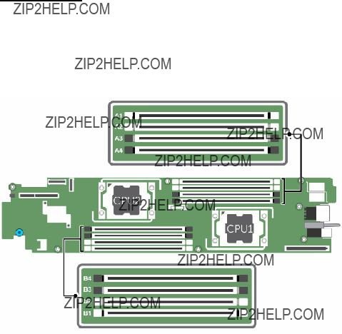
Figure 8. Memory socket locations
Memory channels are organized as follows:
General memory module installation guidelines
Your system supports Flexible Memory Configuration, enabling you to configure and run the system any valid chipset architectural configuration. The following are the recommended guidelines for best performance:
???LRDIMMs and RDIMMs must not be mixed.
???x4 and x8 DRAM based DIMMs can be mixed. For more information, see
???Single or
40
???Populate DIMM sockets only if a processor is installed. For
???Populate all sockets with white release tabs first and then populate the sockets with black release tabs.
???Populate the sockets by highest capacity DIMM in the following order -
???In a
???DIMMs of different sizes can be mixed provided other memory population rules are followed (for example, 4 GB and 8 GB memory modules can be mixed).
???The memory module for DIMM sockets A3, A4, B3, and B4 need to be inserted 180 ?? reverse with regard to the DIMMS in the sockets A1, A2, B1, and B2.
???Follow the
Table 2. Heat sink ??? processor configurations
Four memory channels are allocated to each processor. The allowable configurations depend on the memory mode selected.
NOTE: x4 and x8 DRAM based DIMMs can be mixed providing support for RAS features. However, all guidelines for specific RAS features must be followed. x4 DRAM based DIMMs retain Single Device Data Correction (SDDC) in memory optimized (independent channel) mode. x8 DRAM based DIMMs require Advanced ECC mode to gain SDDC.
The following sections provide additional slot population guidelines for each mode.
Advanced ECC (Lockstep)
Advanced ECC mode extends SDDC from x4 DRAM based DIMMs to both x4 and x8 DRAMs. This protects against single DRAM chip failures during normal operation.
Memory installation guidelines:
???Memory modules must be identical in size, speed, and technology.
???DIMMs installed in memory sockets with white release tabs must be identical and similar rule applies for sockets with black release tabs. This ensures that identical DIMMs are installed in matched pairs - for example, A1 with A2, A3 with A4 and so on.
41

Memory optimized (independent channel) mode
This mode supports Single Device Data Correction (SDDC) only for memory modules that use x4 device width It does not impose any specific slot population requirements.
Memory installation guidelines:
Single CPU
NOTE: Optimized mode permits unbalanced configurations, eg, 1:1:1:0 DIMM per channel (DPC) combinations.
Memory mirroring
Memory Mirroring offers the strongest DIMM reliability mode compared to all other modes, providing improved uncorrectable
Memory installation guidelines:
???Memory modules must be identical in size, speed, and technology.
???DIMMs installed in memory sockets with white release tabs must be identical and similar rule applies for sockets with black release tabs. This ensures that identical DIMMs are installed in matched pairs - for example, A1 with A2, A3 with A4.
NOTE:
Mirroring and Advanced ECC modes require minimum of two DIMMs per CPU and must be populated in pairs of either two or four DIMMs per CPU.
42

Sample memory configurations
The following tables show sample memory configurations that follow the appropriate memory guidelines stated in this section.
NOTE: 1R, 2R, and 4R in the following tables indicate
Table 3. Memory configurations ??? single processor
43

Table 4. Memory configurations ??? dual processor
1R x8, 2133 MT/s
1R x8, 2133 MT/s
2R x4, 2133 MT/s
1R x8, 2133 MT/s
2R x4, 2133 MT/s
2R x8 2133 MT/s
2R x4, 2133 MT/s
2R x8 2133 MT/s
2R x4, 2133 MT/s
4R x4, 2133 MT/s
2R x8 2133 MT/s
2R x4, 2133 MT/s
4R x4, 2133 MT/s
2R x4, 2133 MT/s
4R x4, 2133 MT/s
A1, B1
A1, A2, B1, B2
A1, B1
A1, A2, A3, A4, B1, B2, B3, B4
A1, A2, B1, B2
A1, B1
A1, A2, A3, A4, B1, B2, B3, B4
A1, A2, B1, B2
A1, B1
A1, B1
A1, A2, A3, A4, B1, B2, B3, B4
A1, A2, B1 B2
A1, A2, B1, B2
A1, A2, A3, A4, B1, B2, B3, B4
A1, A2, A3, A4, B1, B2, B3, B4
Removing memory modules
Prerequisites
WARNING: The memory modules are hot to touch for some time after the system has been powered down. Allow time for the memory modules to cool before handling them. Handle the memory modules by the card edges and avoid touching the components or metallic contacts on the memory module.
CAUTION: Many repairs may only be done by a certified service technician. You should only perform troubleshooting and simple repairs as authorized in your product documentation, or as directed by the online or telephone service and support team. Damage due to servicing that is not authorized by Dell is not covered by your warranty. Read and follow the safety instructions that came with the product.
CAUTION: To ensure proper system cooling,
1.Ensure that you read the Safety instructions.
44

2.Follow the procedure listed in Before working inside your system.
3.Remove the cooling shroud.
Steps
1.Locate the appropriate memory module socket(s).
2.To release the memory module from the socket, simultaneously press the ejectors on both ends of the memory module socket.
CAUTION: Handle each memory module only by the card edges, making sure not to touch the middle of the memory module or metallic contacts.
3.Remove the memory module from the socket.
Figure 9. Removing the memory module
3.memory module ejector (2)
Next steps
1.If you are removing the memory module permanently, install a
2.Install the memory module.
3.Install the cooling shroud.
4.Follow the procedure listed in After working inside your system.
Related Links
45

Installing memory modules
Prerequisites
WARNING: The memory modules are hot to touch for some time after the system has been powered down. Allow time for the memory modules to cool before handling them. Handle the memory modules by the card edges and avoid touching the components or metallic contacts on the memory module.
CAUTION: Many repairs may only be done by a certified service technician. You should only perform troubleshooting and simple repairs as authorized in your product documentation, or as directed by the online or telephone service and support team. Damage due to servicing that is not authorized by Dell is not covered by your warranty. Read and follow the safety instructions that came with the product.
NOTE: You must remove a memory module to upgrade a memory module or replace a faulty memory module.
1.Ensure that you read the Safety instructions.
2.Follow the procedure listed in Before working inside your system.
3.Remove the cooling shroud.
4.If installed, remove the memory module or the memory module blank.
Steps
1.Locate the appropriate memory module socket.
2.Press the ejectors on the memory module socket outward to allow the memory module to be inserted into the socket.
CAUTION: Handle each memory module only on either card edge, making sure not to touch the middle of the memory module.
3.Align the the memory module with the key on the socket and insert the memory module in the socket.
NOTE: The memory module socket has an alignment key that allows you to install the memory module in the socket in only one direction.
CAUTION: To prevent damage to the memory module socket during installation, apply pressure at both ends of the memory module evenly. Do not apply pressure to the center of the memory module.
4.Press the memory module with your thumbs to lock the memory module into the socket.
NOTE: When the memory module is properly seated in the socket, the ejectors on the memory module socket align with the ejectors on the other sockets that have memory modules installed.
5.Repeat step 1 through step 4 of this procedure to install the remaining memory modules.
Next steps
1.Install the cooling shroud.
2.Follow the procedure listed in After working inside your system.
3.(Optional) Press <F2> to enter System Setup, and check the System Memory setting. The System Memory Size should reflect the installed memory
46

NOTE: If the System Memory Size is incorrect, one or more of the memory modules may not be installed properly. Ensure that the memory modules are firmly seated in their sockets.
4.Run the system memory test in the system diagnostics.
Related Links
PCIe mezzanine card
The sled supports one x8 PCIe Gen3 mezzanine card. The PCIe card provides an interface between the sled and external storage devices.
NOTE: Ensure that the PCIe mezzanine card is set to Enabled in System Setup.
NOTE: The PCIe mezzanine card slot is available for use only when CPU2 is installed.
Removing the PCIe mezzanine card
Prerequisites
CAUTION: Many repairs may only be done by a certified service technician. You should only perform troubleshooting and simple repairs as authorized in your product documentation, or as directed by the online or telephone service and support team. Damage due to servicing that is not authorized by Dell is not covered by your warranty. Read and follow the safety instructions that came with the product.
1.Ensure that you read the Safety instructions.
2.Follow the procedure listed in Before working inside your system.
3.If connected, disconnect all external storage devices.
4.If connected, disconnect all USB devices.
5.Remove the SSD cage.
6.Keep the Phillips #2 screwdriver ready.
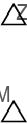
Steps
1.To remove the SSD cage base cover:
a.Place the SSD cage upside down with the USB ports to your right.
b.Remove the screws securing the SSD cage base cover to the SSD cage.
c.Slide the SSD cage base cover back and lift the cover away from the SSD cage.
47

Figure 10. Removal of the SSD cage base cover
3.SSD cage base cover
2.To remove the PCIe mezzanine card:
a.Remove the screws securing the PCIe mezzanine card to the SSD cage.
b.Slide the mezzanine card back and lift the card away from the SSD cage.
c.Remove the PCIe mezzanine card bridge and keep it aside for future use.
CAUTION: To prevent damage to the PCIe mezzanine card, you must hold the card only by its edges.
48

Next steps
1.Install the PCIe mezzanine card.
2.Install the SSD cage.
3.If applicable, reconnect the disconnected storage devices.
4.If applicable, reconnect the disconnected USB devices.
5.Follow the procedure listed in After working inside your system.
Related Links
49

Installing the PCIe mezzanine card
Prerequisites
CAUTION: Many repairs may only be done by a certified service technician. You should only perform troubleshooting and simple repairs as authorized in your product documentation, or as directed by the online or telephone service and support team. Damage due to servicing that is not authorized by Dell is not covered by your warranty. Read and follow the safety instructions that came with the product.
NOTE: You must remove the PCIe mezzanine card to replace a faulty PCIe mezzanine card.
1.Ensure that you read the Safety instructions.
2.Follow the procedure listed in Before working inside your system.
3.If connected, disconnect all external storage devices.
4.If connected, disconnect all USB devices.
5.Remove the SSD cage.
6.Remove the PCIe mezzanine card.
7.Keep the Phillips #2 screwdriver ready.
Steps
1.To install the PCIe mezzanine card:
a.Place the SSD cage upside down with the USB ports to your right.
b.Slide the PCIe mezzanine card on to the SSD cage.
c.Secure the card in place with the screws.
d.Install the PCIe mezzanine card bridge.
CAUTION: To prevent damage to the PCIe mezzanine card, you must hold the card only by its edges.
2.To install the SSD cage base cover :
a.Slide the SSD cage base cover into place.
b.Secure the SSD cage base cover to the SSD cage.
3.Align the guide slots on the SSD cage with the guide pins on the chassis.
4.Press down the SSD cage till the connectors on the SSD cage completely engage with the corresponding connectors on the system board.
Next steps
1.Install the SSD cage.
2.If applicable, reconnect the disconnected storage devices.
3.If applicable, reconnect the disconnected USB devices.
4.Follow the procedure listed in After working inside your system.
Related Links
50
Internal Dual SD Module (IDSDM) card
The IDSDM card provides one SD card slot, one vFlash card slot and a shared USB interface for the embedded hypervisor. This card offers the following features:
???Single card operation ??? single card operation is supported, but without redundancy.
???Dual card operation ??? dual card operation is supported and can be configured with redundancy.
NOTE: When the Redundancy option is set to Mirror Mode in the Integrated Devices screen of the System Setup, the information is replicated from one SD card to another.
Removing an internal SD card
Prerequisites
CAUTION: Many repairs may only be done by a certified service technician. You should only perform troubleshooting and simple repairs as authorized in your product documentation, or as directed by the online or telephone service and support team. Damage due to servicing that is not authorized by Dell is not covered by your warranty. Read and follow the safety instructions that came with the product.
1.Ensure that you read the Safety instructions.
2.Follow the procedure listed in Before working inside your system.
3.Enter System Setup and ensure that the Internal SD Card Port is enabled.
NOTE: When an SD card failure occurs, on the next reboot, the system displays a message indicating the failure.
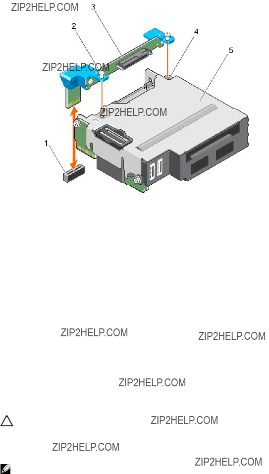
Steps
1.Locate the SD card slot on the internal dual SD module (IDSDM) card.
2.Press the card to release it from the slot and remove the card.
51

Figure 12. Replacing an internal SD card
Next steps
1.Follow the procedure listed in After working inside your system.
2.Enter System Setup and ensure that the Internal SD Card Port is enabled.
3.Check if the new SD card is functioning properly. If the problem persists, see Troubleshooting an internal SD card.
Installing an internal SD card
Prerequisites
1.Ensure that you read the Safety instructions.
2.Follow the procedure listed in Before working inside your system.
3.If applicable, remove the SD card.
CAUTION: Many repairs may only be done by a certified service technician. You should only perform troubleshooting and simple repairs as authorized in your product documentation, or as directed by the online or telephone service and support team. Damage due to servicing that is not authorized by Dell is not covered by your warranty. Read and follow the safety instructions that came with the product.
NOTE: To use an SD card with your system, ensure that the Internal SD Card Port is enabled in System Setup.
Steps
1.Locate the SD card connector on the internal dual SD module. Align the keyed end of the SD card into the slot and insert the card into the slot
52

 NOTE: The slot is keyed to ensure correct insertion of the card.
2.Press the card into the card slot to lock it into place.
Next steps
1.Follow the procedure listed in After working inside your system.
2.Enter System Setup and ensure that the Internal SD Card Port is enabled.
3.Check if the new SD card is functioning properly. If the problem persists, see Troubleshooting an internal SD card.
Related Links
Removing the IDSDM card
Prerequisites
CAUTION: Many repairs may only be done by a certified service technician. You should only perform troubleshooting and simple repairs as authorized in your product documentation, or as directed by the online or telephone service and support team. Damage due to servicing that is not authorized by Dell is not covered by your warranty. Read and follow the safety instructions that came with the product.
1.Ensure that you read the Safety instructions.
2.Follow the procedure listed in Before working inside your system.
3.If connected, disconnect all USB devices.
4.If installed, remove the SD card(s).
5.Remove the SSD cage.
6.Keep the Phillips #2 screwdriver ready.
Steps
1.Remove the screws securing the IDSDM card to the SSD cage.
2.Lift the IDSDM card till it disengages from the standoff and slide the IDSDM card away out of the SSD cage.
 CAUTION: To prevent damage to the IDSDM card, you must hold the card only by its edges.
53

5.IDSDM card
Next steps
1.Install the SSD cage.
2.Install the IDSDM card.
3.If applicable, install the SD cards.
4.Reconnect any disconnected USB devices.
5.Follow the procedure listed in After working inside your system.
Related Links
54

Installing the IDSDM card
Prerequisites
CAUTION: Many repairs may only be done by a certified service technician. You should only perform troubleshooting and simple repairs as authorized in your product documentation, or as directed by the online or telephone service and support team. Damage due to servicing that is not authorized by Dell is not covered by your warranty. Read and follow the safety instructions that came with the product.
NOTE: You must remove the IDSDM card to replace a faulty IDSDM card.
1.Ensure that you read the Safety instructions.
2.Follow the procedure listed in Before working inside your system.
3.Remove the SD card.
4.Disconnect any connected USB devices.
5.Remove the SSD cage.
6.Remove the IDSDM card.
7.Keep the Phillips #2 screwdriver ready.
CAUTION: To prevent damage to the IDSDM card, you must hold the card only by its edges.
Steps
1.Slide the IDSDM card into the slot on the SSD cage.
2.Align the IDSDM card with the standoff on the SSD cage and the USB port slots on the front panel.
3.Secure the IDSDM card to the SSD cage with the screws.
Next steps
1.Install the SSD cage.
2.If applicable, install the SD card(s).
3.If applicable, reconnect any disconnected USB devices.
4.Follow the procedure listed in After working inside your system.
Related Links
55

SD vFlash card
You can use an SD vFlash card with your system. The card slot is located on the IDSDM card. You can remove and install the SD vFlash card
Replacing the SD vFlash card
Prerequisites
CAUTION: Many repairs may only be done by a certified service technician. You should only perform troubleshooting and simple repairs as authorized in your product documentation, or as directed by the online or telephone service and support team. Damage due to servicing that is not authorized by Dell is not covered by your warranty. Read and follow the safety instructions that came with the product.
1.Ensure that you read the Safety instructions.
2.Follow the procedure listed in Before working inside your system.
3.If installed, remove the SD vFlash card from the card slot.
Steps
1.Insert the
 NOTE: The slot is keyed to ensure correct insertion of the card.
2.Press the card into the card slot to lock it into place.
Figure 14. Replacing the SD vFlash card
56

Next steps
Follow the procedure listed in After working inside your system.
Installing the SD vFlash card
Prerequisites
1.Ensure that you read the Safety instructions.
2.Follow the procedure listed in Before working inside your system.
CAUTION: Many repairs may only be done by a certified service technician. You should only perform troubleshooting and simple repairs as authorized in your product documentation, or as directed by the online or telephone service and support team. Damage due to servicing that is not authorized by Dell is not covered by your warranty. Read and follow the safety instructions that came with the product.
NOTE: To use an SD card with your system, ensure that the Internal SD Card Port is enabled in System Setup.
Steps
1.Locate the SD card connector on the internal dual SD module. Align the SD card appropriately and insert the
 NOTE: The slot is keyed to ensure correct insertion of the card.
2.Press the card into the card slot to lock it into place.
Next steps
1.Follow the procedure listed in After working inside your system.
LAN on Motherboard (LOM) riser card
The LOM riser card installed in your system is an integrated network interface controller. You can remove and install the LOM riser card.
Removing the LOM riser card
Prerequisites
CAUTION: Many repairs may only be done by a certified service technician. You should only perform troubleshooting and simple repairs as authorized in your product documentation, or as directed by the online or telephone service and support team. Damage due to servicing that is not authorized by Dell is not covered by your warranty. Read and follow the safety instructions that came with the product.
1.Ensure that you read the Safety instructions.
2.Follow the procedure listed in Before working inside your system.
3.Keep the Phillips #2 screwdriver ready.
Steps
1.Remove the two screws that secure the LOM riser card to the system board.
2.Lift the card from the system board.
57

Next steps
1.Install the LOM riser card.
2.Follow the procedure listed in After working inside your system.
Related Links
Installing the LOM riser card
Prerequisites
CAUTION: Many repairs may only be done by a certified service technician. You should only perform troubleshooting and simple repairs as authorized in your product documentation, or as directed by the online or telephone service and support team. Damage due to servicing that is not authorized by Dell is not covered by your warranty. Read and follow the safety instructions that came with the product.
NOTE: You must remove the LOM riser card to replace a faulty LOM riser card or service other components inside the system.
1.Ensure that you read the Safety instructions.
2.Follow the procedure listed in Before working inside your system.
3.Keep the Phillips #2 screwdriver ready.
58

Steps
1.Align the screw holes on the card with the standoffs on the system board.
CAUTION: To prevent damage to the LOM riser card, you must hold the card only by its edges.
2.Press the card into place until the card connector fits into the corresponding connector on the system board.
3.Secure the card with the two screws.
Next steps
Follow the procedure listed in After working inside your system.
Processors
Your system supports up to two Intel Haswell EP product family processors.
NOTE: The sled supports processors with the wattages listed below:
???Up to two 120 W processors are supported.
???A single 140 W processor is supported.
NOTE: Mixing processors of different wattages is not supported.
Use the following procedure when:
???Installing an additional processor.
???Replacing a processor.
Removing a heat sink
Prerequisites
CAUTION: Many repairs may only be done by a certified service technician. You should only perform troubleshooting and simple repairs as authorized in your product documentation, or as directed by the online or telephone service and support team. Damage due to servicing that is not authorized by Dell is not covered by your warranty. Read and follow the safety instructions that came with the product.
NOTE: This is a Field Replaceable Unit (FRU). Removal and installation procedures should be performed only by Dell certified service technicians.
CAUTION: Never remove the heat sink from a processor unless you intend to remove the processor. The heat sink is necessary to maintain proper thermal conditions.
NOTE: To ensure proper system cooling, you must install a processor blank in any empty processor socket.
1.Ensure that you read the Safety instructions.
2.Follow the procedure listed in Before working inside your system.
3.Remove the cooling shroud.
4.Keep the Phillips #2 screwdriver ready.
WARNING: The heat sink will be hot to touch for some time after the system has been powered down. Allow the heat sink to cool before removing it.
59

Steps
1.To remove a 120 W heat sink, perform the following steps.
a.Loosen one of the screws that secure the heat sink to the system board. Wait 30 seconds for the heat sink to loosen from the processor.
b.Remove the screw diagonally opposite the screw you first removed.
c.Repeat the procedure for the remaining two screws.
Figure 16. Removing and installing the 120 W heat sink
2.To remove a 140 W heat sink, perform the following steps.
a.Loosen one of the screws that secure the heat sink over CPU 1 to the system board. Wait 30 seconds for the heat sink to loosen from the processor.
b.Remove the screw diagonally opposite the screw you first removed.
c.Repeat the procedure for the remaining four screws.
60
Figure 17. Removing and installing the 140 W heat sink
Next steps
1.Remove the processor.
Related Links
Removing a processor
Prerequisites
CAUTION: Many repairs may only be done by a certified service technician. You should only perform troubleshooting and simple repairs as authorized in your product documentation, or as directed by the online or telephone service and support team. Damage due to servicing that is not authorized by Dell is not covered by your warranty. Read and follow the safety instructions that came with the product.
NOTE: This is a Field Replaceable Unit (FRU). Removal and installation procedures should be performed only by Dell certified service technicians.
WARNING: The processor will be hot to touch for some time after the system has been powered down. Allow the processor to cool before removing it.
CAUTION: The processor is held in its socket under strong pressure. Be aware that the release lever can spring up suddenly if not firmly grasped.
61
NOTE: To ensure proper system cooling, you must install a processor blank in any empty processor socket.
1.Ensure that you read the Safety instructions.
2.Follow the procedure listed in Before working inside your system.
3.If you are upgrading your system (from a single processor system to a dual processor system or a processor with a higher processor bin), download the latest system BIOS version from dell.com/ support and follow the instructions included in the compressed download file to install the update on your system.
 NOTE: You can update the system BIOS by using Lifecycle Controller.
4.Remove the cooling shroud.
5.Remove the heat sink.
6.Keep the Phillips #2 screwdriver ready.
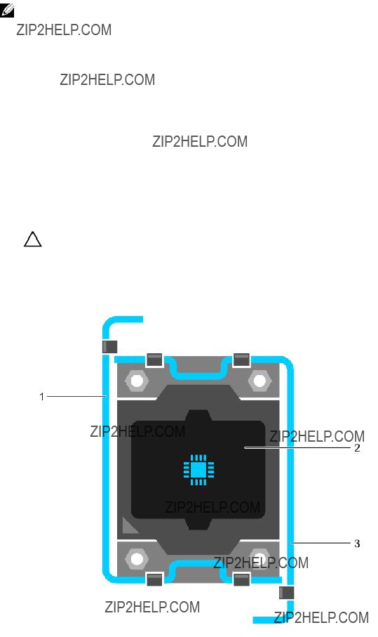
Steps
1.Using a clean,
CAUTION: The processor is held in its socket under strong pressure. Be aware that the release lever can spring up suddenly if not firmly grasped.
2.Position your thumb firmly over the
Figure 18. Processor shield opening and closing lever sequence
62

3.
3.Hold the tab on the processor shield and rotate the shield upward and out of the way.
4.Lift the processor out of the socket and leave the release lever up so that the socket is ready for the new processor.
CAUTION: If you are permanently removing a processor, you must install a socket protective cap and a processor blank in the vacant socket to ensure proper system cooling. The processor blank covers the vacant sockets for the DIMMs and the processor.
Next steps
1.If you are removing the processor permanently, install the
2.Install a new processor.
3.Install the heat sink.
4.Follow the procedure listed in After working inside your system.
Related Links
63

Installing a
Installing a processor
Prerequisites
CAUTION: Many repairs may only be done by a certified service technician. You should only perform troubleshooting and simple repairs as authorized in your product documentation, or as directed by the online or telephone service and support team. Damage due to servicing that is not authorized by Dell is not covered by your warranty. Read and follow the safety instructions that came with the product.
NOTE: This is a Field Replaceable Unit (FRU). Removal and installation procedures should be performed only by Dell certified service technicians.
1.Ensure that you read the Safety instructions.
2.Follow the procedure listed in Before working inside your system.
3.If you are upgrading your system (from a single processor system to a dual processor system or a processor with a higher processor bin) download the latest system BIOS version from dell.com/ support and follow the instructions included in the compressed download file to install the update on your system.
 NOTE: You can update the system BIOS by using Lifecycle Controller.
4.Remove the processor blank.
5.Keep the Phillips #2 screwdriver ready.
NOTE: If you are installing a single processor, it must be installed in socket CPU 1.
Steps
1.Unpack the new processor.
2.Locate the processor socket.
3.If installed, remove the socket protective cap.
4.Unlatch and rotate the
5.Hold the tab on the processor shield and lift the shield and move it out of the way.
NOTE: It is recommended that you install/remove the socket protective cap from the processor shield with the processor shield in the open position.
6.If installed, remove the socket protective cap from the processor shield. To remove the socket protective cap, push the cap from the inside of the processor shield and move it away from the socket pins.
CAUTION: Positioning the processor incorrectly can permanently damage the system board or the processor. Be careful not to damage the pins in the socket.
CAUTION: Do not use force to seat the processor. When the processor is positioned correctly, it engages easily into the socket.
7.Install the processor in the socket:
64

a.Identify the
b.Align the
c.Place the processor on the socket such that the slots on the processor align with the socket keys.
CAUTION: Do not use force to seat the processor. When the processor is positioned correctly, it engages easily into the socket.
The sled uses a ZIF processor socket. Do not use force while installing the processor in the socket
d.Close the processor shield.
e.Rotate the
Next steps
NOTE: Ensure that you install the heat sink after you install the processor. The heat sink is necessary to maintain proper thermal conditions.
1.Install the heat sink.
2.Follow the procedure listed in After working inside your system.
Related Links
Removing a
Installing a heat sink
Prerequisites
CAUTION: Many repairs may only be done by a certified service technician. You should only perform troubleshooting and simple repairs as authorized in your product documentation, or as directed by the online or telephone service and support team. Damage due to servicing that is not authorized by Dell is not covered by your warranty. Read and follow the safety instructions that came with the product.
NOTE: This is a Field Replaceable Unit (FRU). Removal and installation procedures should be performed only by Dell certified service technicians.
1.Ensure that you read the Safety instructions.
2.Follow the procedure listed in Before working inside your system.
3.Install the processor.
4.Keep the Phillips #2 screwdriver ready.
NOTE: If you are installing a single processor, it must be installed in socket CPU 1.
Steps
1.If you are using an existing heat sink, remove the thermal grease from the heat sink by using a clean
2.Using the thermal grease syringe included with your processor kit, apply the grease in a thin spiral on the top of the processor as shown in the figure.
CAUTION: Applying too much thermal grease can result in excess grease coming in contact with and contaminating the processor socket.
NOTE: The thermal grease syringe is intended for
65
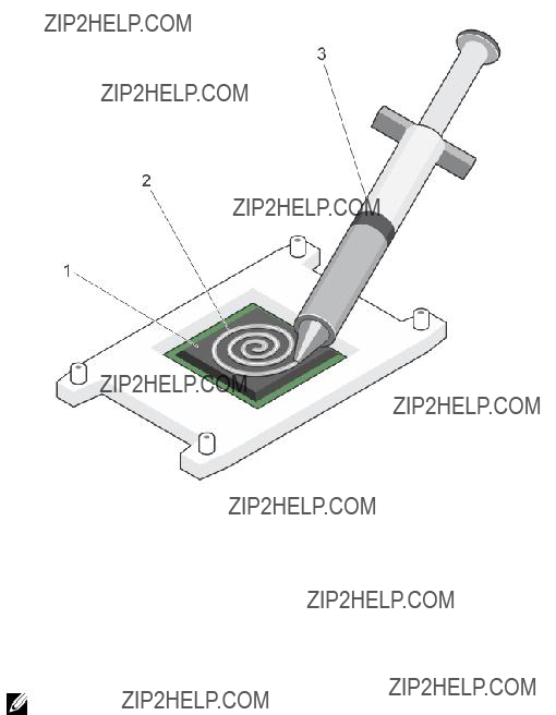
Figure 20. Applying thermal grease on the top of the processor
3.thermal grease syringe
3.Place the heat sink on the processor.
4.Tighten one of the four screws to secure the heat sink to the system board.
5.Tighten the screw diagonally opposite to the first screw you tightened.
NOTE: Do not
6.Repeat the procedure for the remaining screws.
Next steps
1.Install the cooling shroud.
2.Follow the procedure listed in After working inside your system.
3.While booting, press <F2> to enter System Setup and check that the processor information matches the new system configuration.
4.Run system diagnostics to verify that the new processor operates correctly.
Related Links
66

The
CAUTION: If you are permanently removing a processor, you must install a socket protective cap and a
Removing a
Prerequisites
CAUTION: Many repairs may only be done by a certified service technician. You should only perform troubleshooting and simple repairs as authorized in your product documentation, or as directed by the online or telephone service and support team. Damage due to servicing that is not authorized by Dell is not covered by your warranty. Read and follow the safety instructions that came with the product.
1.Ensure that you read the Safety instructions.
2.Follow the procedure listed in Before working inside your system.
3.Remove the cooling shroud.
Steps
1.Press the DIMM latches to unlock the
2.Hold the
67

Figure 21. Removing and installing a
Next steps
1.Install the processor.
2.Install the heat sink.
3.Install the cooling shroud.
4.If you are removing a processor permanently, install the
5.Follow the procedure listed in After working inside your system.
Related Links
Installing a
Installing a
Prerequisites
CAUTION: Many repairs may only be done by a certified service technician. You should only perform troubleshooting and simple repairs as authorized in your product documentation, or as directed by the online or telephone service and support team. Damage due to servicing that is not authorized by Dell is not covered by your warranty. Read and follow the safety instructions that came with the product.
68

NOTE: You must remove the
1.Ensure that you read the Safety instructions.
2.Follow the procedure listed in Before working inside your system.
3.Remove the cooling shroud.
Steps
1.Align the standoffs on the
2.Press the
Next steps
1.Ensure that you install a
2.Install the cooling shroud.
3.Follow the procedure listed in After working inside your system.
Related Links
Solid State Drives (SSD)
The PowerEdge FC430 supports one or two 1.8 inch uSATA SSDs. The SSDs are supplied in special hot swap drive carriers that fit in the drive bays and these drives connect to the system board through the SSD backplane board.
SSD installation guidelines
In a dual SSD bay sled that has a single SSD installed, an SSD blank must be installed in the vacant drive bay to maintain proper airflow.
Shutdown procedure for servicing an SSD
NOTE: This section applies only to situations where the sled must be powered down to service an SSD.
If you need to service an SSD, turn off the sled and before removing the SSD wait for 30 seconds after the sled???s indicator turns off. Otherwise, the SSD may not be recognized after it is reinstalled and the sled is powered on again.
Removing an SSD from an SSD carrier
Prerequisites
CAUTION: Many repairs may only be done by a certified service technician. You should only perform troubleshooting and simple repairs as authorized in your product documentation, or as directed by the online or telephone service and support team. Damage due to servicing that is not authorized by Dell is not covered by your warranty. Read and follow the safety instructions that came with the product.
69

1.Remove the SSD carrier out of the sled.
2.Ensure that you read the Safety instructions.
Steps
Pull the rails on the side of the carrier and lift the SSD out of the carrier.
Figure 22. Removing and installing an SSD in an SSD carrier
Next steps
1.Install an SSD in the SSD carrier.
2.Install the SSD carrier into the sled.
Related Links
Installing an SSD into an SSD carrier
Installing an SSD into an SSD carrier
Prerequisites
CAUTION: Many repairs may only be done by a certified service technician. You should only perform troubleshooting and simple repairs as authorized in your product documentation, or as directed by the online or telephone service and support team. Damage due to servicing that is not authorized by Dell is not covered by your warranty. Read and follow the safety instructions that came with the product.
NOTE: You must remove the SSD from an SSD carrier to replace a faulty SSD from an SSD carrier.
1.Ensure that you read the Safety instructions.
2.Remove the SSD carrier out of the sled.
3.Remove the SSD from the SSD carrier.
70
Steps
Insert the SSD into the SSD carrier with the connector end of the SSD toward the back of the carrier. When aligned correctly, the back of the SSD is flush with the back of the SSD carrier.
Next steps
Install the SSD carrier into the sled.
Related Links
Removing an SSD from an SSD carrier
Removing an SSD carrier
Prerequisites
CAUTION: Many repairs may only be done by a certified service technician. You should only perform troubleshooting and simple repairs as authorized in your product documentation, or as directed by the online or telephone service and support team. Damage due to servicing that is not authorized by Dell is not covered by your warranty. Read and follow the safety instructions that came with the product.
1.Ensure that you read the Safety instructions.
2.Take the SSD offline and wait until the SSD indicator LEDs on the carrier are off.
NOTE: When all indicators are off, the drive is ready for removal. See your operating system documentation for more information on taking the SSD offline.
NOTE: All operating systems do not support
Steps
1.Press the release button to open the SSD carrier handle.
2.Slide the SSD carrier out until it is free of the SSD slot.
71

Figure 23. Removing and installing an SSD
3.SSD carrier handle
Next steps
1.If you are removing an SSD permanently, install the SSD blank. If you are installing a new SSD, see Installing an SSD carrier.
2.Follow the procedure listed in After working inside your system.
Related Links
Installing an SSD carrier
Prerequisites
CAUTION: When a replacement hot swappable SSD is installed and the sled is powered on, the SSD automatically begins to rebuild. Make absolutely sure that the replacement SSD is blank or contains data that you wish to have
NOTE: You must remove an SSD to upgrade an SSD or replace a faulty SSD.
1.Ensure that you read the Safety instructions.
2.Remove the SSD blank.
3.Install the SSD in the SSD carrier.
NOTE: All operating systems do not support hot swappable drive installation. See the documentation supplied with your operating system.
72
Steps
1.Press the release button to open the SSD carrier handle.
2.Slide the SSD carrier into the drive bay and push it until the handle makes contact with the sled.
3.Rotate the carrier handle to the closed position while pushing the carrier into the slot until it locks into place.
The status LED indicator displays a steady green light if the drive is installed correctly. The drive carrier LED green indicator flashes as the drive rebuilds.
Next steps
Follow the procedure listed in After working inside your system.
Related Links
Installing an SSD into an SSD carrier
Removing an SSD blank
Prerequisites
CAUTION: Many repairs may only be done by a certified service technician. You should only perform troubleshooting and simple repairs as authorized in your product documentation, or as directed by the online or telephone service and support team. Damage due to servicing that is not authorized by Dell is not covered by your warranty. Read and follow the safety instructions that came with the product.
CAUTION: To maintain proper system cooling, all empty SSD slots must have a SSD blank installed.
Ensure that you read the Safety instructions.
Steps
Press the release latch and slide the SSD blank out of the SSD slot.
73

Figure 24. Removing and installing an SSD blank
Next steps
Install the SSD
Related Links
Installing an SSD blank
Prerequisites
1.Ensure that you read the Safety instructions.
2.Remove an SSD.
Steps
Insert the SSD blank into the SSD slot until the release latch clicks into place.
Related Links
Removing the SSD cage
Prerequisites
CAUTION: Many repairs may only be done by a certified service technician. You should only perform troubleshooting and simple repairs as authorized in your product documentation, or as directed by the online or telephone service and support team. Damage due to servicing that is not authorized by Dell is not covered by your warranty. Read and follow the safety instructions that came with the product.
1.Ensure that you read the Safety instructions.
74

2.Follow the procedure listed in Before working inside your system.
3.Remove the SSD(s).
4.Disconnect all connected USB devices.
5.Keep the Phillips #1 screwdriver ready.
Steps
1.Remove the four screws securing the SSD cage to the chassis.
2.Holding the SSD cage by its edges, lift it away from the sled.
5.guide pin (4)
Next steps
1.Install the SSD cage.
2.Install the SSD(s).
3.Reconnect the USB devices.
4.Follow the procedure listed in After working inside your system.
Related Links
75

Installing the SSD cage
Prerequisites
CAUTION: Many repairs may only be done by a certified service technician. You should only perform troubleshooting and simple repairs as authorized in your product documentation, or as directed by the online or telephone service and support team. Damage due to servicing that is not authorized by Dell is not covered by your warranty. Read and follow the safety instructions that came with the product.
NOTE: You must remove the SSD cage to replace a faulty SSD cage or service other components inside the system.
1.Ensure that you read the Safety instructions.
2.Follow the procedure listed in Before working inside your system.
3.Keep the Phillips #1 screwdriver ready.
Steps
1.Align the slots on the sides of the SSD cage with the guide pins on the chassis.
2.Push the SSD cage into the chassis until the screw holes on the chassis are aligned with the holes on the SSD cage..
3.Slide the SSD cage into the chassis till the IDSDM card connector engages completely with the connector on the system board.
4.Secure the SSD cage to the chassis with the screws.
Next steps
1.Install the SSD backplane.
2.Install the SSDs.
3.Follow the procedure listed in After working inside your system.
Related Links
Configuring the boot drive
The drive or device from which the system boots is determined by the boot order specified in the System Setup.
76

Solid State Drive (SSD) backplane
The SSD backplane of your system allows you to use
Removing the SSD backplane
Prerequisites
CAUTION: Many repairs may only be done by a certified service technician. You should only perform troubleshooting and simple repairs as authorized in your product documentation, or as directed by the online or telephone service and support team. Damage due to servicing that is not authorized by Dell is not covered by your warranty. Read and follow the safety instructions that came with the product.
CAUTION: To prevent damage to the SSDs and the SSD backplane, you must remove the SSD carriers from the sled before removing the SSD backplane.
CAUTION: You must note the bay number of each SSD and temporarily label them before removal so that you can reinstall them into their original bays.
1.Ensure that you read the Safety instructions.
2.Follow the procedure listed in Before working inside your system.
3.Remove the SSD carrier(s).
4.Keep the Phillips #2 screwdriver ready.
Steps
1.Loosen the two captive screws on the backplane touch points that secure the SSD backplane to the SSD cage.
2.Holding the backplane at the touch points, lift the SSD backplane till it disengages from the connector on the system board.
3.Lift the backplane away from the SSD cage.
77
5.SSD cage
Next steps
1.Install the SSD backplane.
2.Install the SSD carrier(s).
3.Follow the procedure listed in After working inside your system.
Related Links
Installing the SSD backplane
Prerequisites
CAUTION: Many repairs may only be done by a certified service technician. You should only perform troubleshooting and simple repairs as authorized in your product documentation, or as directed by the online or telephone service and support team. Damage due to servicing that is not authorized by Dell is not covered by your warranty. Read and follow the safety instructions that came with the product.
NOTE: You must remove the SSD backplane to replace a faulty SSD backplane.
78

1.Ensure that you read the Safety instructions.
2.Follow the procedure listed in Before working inside your system.
3.Remove the SSD backplane.
4.Keep the Phillips #2 screwdriver ready.
Steps
1.Align the screws on the SSD backplane with the screw holes on the SSD cage.
2.Press the SSD backplane into place until the retention screws on the SSD backplane engage with the screw holes on the SSD cage.
3.Ensure that the backplane connector is seated firmly in the socket on the system board and tighten the two captive screws to secure the backplane to the SSD cage.
Next steps
1.Install the SSD carriers into their original bays.
2.Follow the procedure listed in After working inside your system.
Related Links
NVRAM backup battery
The NVRAM backup battery installed in your system helps to retain the BIOS settings and configurations even if the power is switched off.
Replacing the NVRAM backup battery
Prerequisites
WARNING: There is a danger of a new battery exploding if it is incorrectly installed. Replace the battery only with the same or equivalent type recommended by the manufacturer. Discard used batteries according to the manufacturer's instructions. See the safety instructions that came with your system for additional information.
CAUTION: Many repairs may only be done by a certified service technician. You should only perform troubleshooting and simple repairs as authorized in your product documentation, or as directed by the online or telephone service and support team. Damage due to servicing that is not authorized by Dell is not covered by your warranty. Read and follow the safety instructions that came with the product.
1.Ensure that you read the Safety instructions.
2.Follow the procedure listed in Before working inside your system.
3.Remove the cooling shroud.
Steps
1.Locate the system battery.
2.Hold the battery and pull it toward the positive side of the battery till the battery disengages from the connector.
3.Lift the battery up and away from the system.
4.To install a new system battery, hold the battery with the "+" sign facing the positive side of the battery connector.
79
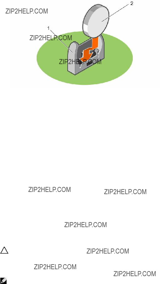
5.Place the battery straight down into the connector and push the positive side of the battery till the battery snaps into place.
Figure 27. Replacing the NVRAM backup battery
Next steps
1.Install the cooling shroud.
2.Follow the procedure listed in After working inside your system.
3.Enter System Setup to confirm that the battery is operating properly.
4.Enter the correct time and date in the System Setup's Time and Date fields.
5.Exit System Setup.
6.To test the freshly installed battery, leave the sled disconnected for at least an hour.
7.Reconnect the sled after an hour has passed.
8.Enter System Setup and if the time and date are still incorrect, see Getting help.
Related Links
System board
Removing the system board
Prerequisites
CAUTION: Many repairs may only be done by a certified service technician. You should only perform troubleshooting and simple repairs as authorized in your product documentation, or as directed by the online or telephone service and support team. Damage due to servicing that is not authorized by Dell is not covered by your warranty. Read and follow the safety instructions that came with the product.
NOTE: This is a Field Replaceable Unit (FRU). Removal and installation procedures should be performed only by Dell certified service technicians.
80
CAUTION: If you are using Trusted Program Module (TPM) with an encryption key, you may be prompted to create a recovery key during program or System Setup. Be sure to create and safely store this recovery key. If you replace this system board, you must supply the recovery key when you restart your system or program before you can access the encrypted data on your hard drives.
CAUTION: Do not attempt to remove the TPM
1.Ensure that you read the Safety instructions.
2.Follow the procedure listed in Before working inside your system.
3.Remove the following components:
???Processor(s) and heat sink(s)
???Memory modules
???Cooling shroud
???SSD carriers
???SSD backplane
???SSD cage
???PCIe mezzanine card
???LOM riser card
4.Keep the Phillips #2 screwdriver, along with the 4 mm and 5 mm Hex nut drivers ready.
CAUTION: Do not lift the system board by holding a memory module, processor, or other components.
CAUTION: You must temporarily label the SSD before removal so that you can replace them in their original bays.
WARNING: The processor and heat sink can become extremely hot. Be sure the processor has had sufficient time to cool before handling.
WARNING: The memory modules are hot to touch for some time after the system has been powered down. Allow the memory modules to cool before handling them. Handle the memory modules by the card edges and avoid touching the components.
Steps
1.Remove the screws on the system board that secure the system board to the chassis.
2.By holding the system board handle, lift the system board away from the chassis.
81

Figure 29. Removing and installing the system board
Next steps
1.Install the system board.
2.Follow the procedure listed in After working inside your system.
Related Links
82

Installing the system board
Prerequisites
CAUTION: Many repairs may only be done by a certified service technician. You should only perform troubleshooting and simple repairs as authorized in your product documentation, or as directed by the online or telephone service and support team. Damage due to servicing that is not authorized by Dell is not covered by your warranty. Read and follow the safety instructions that came with the product.
NOTE: This is a Field Replaceable Unit (FRU). Removal and installation procedures should be performed only by Dell certified service technicians.
NOTE: You must remove the system board to replace a faulty system board.
1.Ensure that you read the Safety instructions.
2.Follow the procedure listed in Before working inside your system.
3.Remove the system board.
4.Unpack the new system board assembly.
5.Keep the Phillips #2 screwdriver, the 4 mm and 5 mm Hex nut drivers ready.
CAUTION: Do not lift the system board by holding a memory module, processor, or other components.
CAUTION: Take care not to damage the system identification button while placing the system board into the chassis.
Steps
1.Align the system board with the standoffs on the chassis.
2.Secure the system board to the chassis with the screws.
Next steps
1.Install the Trusted Platform Module (TPM). For information on how to install TPM, see Installing the Trusted Platform Module .For information on TPM, see Trusted Platform Module.
2.Install the following components:
???LOM riser card
???PCIe mezzanine card
???SSD cage
???SSD backplane
???SSD carriers
 NOTE: Ensure that you reinstall the SSD carriers into their original bays.
???Cooling shroud
???Memory modules
???Processor(s) and heat sink(s)
3.Follow the procedure listed in After working inside your system.
 NOTE: If you are not installing the sled in the enclosure, install the I/O connector cover.
83
4.Import your new or existing iDRAC Enterprise license. See the iDRAC8 User's Guide at dell.com/ esmmanuals.
5.Ensure that you:
a.Use the Easy Restore feature to restore the Service Tag. For more information, see Restoring the Service Tag using Easy Restore.
b.If the Service Tag is not backed up in the backup flash device, enter the system Service Tag manually. For more information, see Entering the system Service Tag using System Setup.
c.Update the BIOS and iDRAC versions.
d.
Related Links
Installing the PCIe mezzanine card
Restoring the Service Tag using Easy Restore
Use the Easy Restore feature if you do not know the Service Tag of your system. The Easy Restore feature allows you to restore your system???s Service Tag, license, UEFI configuration, and the system configuration data after replacing the system board. All data is backed up in an rSPI card automatically. If BIOS detects a new system board and the Service Tag in the rSPI card, BIOS prompts the user to restore the backup information.
1.Turn on the system.
If BIOS detects a new system board, and if the Service Tag is present in the rSPI card, BIOS displays the Service Tag, the status of the license, and the UEFI Diagnostics version.
2.Do one of the following:
???Press Y to restore the Service Tag, license, and diagnostics information.
???Press N to navigate to the Lifecycle Controller based restore options.
???Press <F10> to restore data from a previously created Hardware Server Profile.
After the restore process is complete, BIOS prompts to restore the system configuration data.
3.Do one of the following:
???Press Y to restore the system configuration data.
???Press N to use the default configuration settings.
After the restore process is complete, the system reboots.
84

Entering the system Service Tag using System Setup
If you know the system Service Tag, use System Setup menu to enter the Service Tag.
1.Turn on the system.
2.Press <F2> to enter System Setup.
3.Click Service Tag Settings.
4.Enter the Service Tag.
NOTE: You can enter the Service Tag only when the Service Tag field is empty. Ensure that you enter the correct Service Tag. Once the Service Tag is entered, it cannot be updated or changed.
5.Click Ok.
6.Import your new or existing iDRAC Enterprise license.
For more information, see Integrated Dell Remote Access Controller User's Guide, at dell.com/ esmmanuals.
Trusted Platform Module
The Trusted Platform Module (TPM) is used to generate or store keys, protect or authenticate passwords, and create or store digital certificates. TPM can also be used to enable the BitLocker hard drive encryption feature in Windows Server.
CAUTION: Do not attempt to remove the Trusted Platform Module (TPM) from the system board. Once the TPM is installed, it is cryptographically bound to that specific system board. Any attempt to remove an installed TPM breaks the cryptographic binding, and it cannot be re- installed or installed on another system board.
Installing the Trusted Platform Module
Prerequisites
CAUTION: Many repairs may only be done by a certified service technician. You should only perform troubleshooting and simple repairs as authorized in your product documentation, or as directed by the online or telephone service and support team. Damage due to servicing that is not authorized by Dell is not covered by your warranty. Read and follow the safety instructions that came with the product.
Ensure that you read the Safety instructions.
Steps
1.Align the edge connectors on the TPM with the slot on the TPM connector.
2.Insert the TPM into the TPM connector such that the plastic bolt aligns with the slot on the system board.
3.Press the plastic bolt until the bolt snaps into place.
85
5.slot on the system board
Initialize the TPM.
For more information on initializing the TPM, see
The TPM Status changes to Enabled, Activated.
1.While booting your system, press <F2> to enter System Setup.
2.In the System Setup Main Menu, click System BIOS ??? System Security Settings.
3.In the TPM Security option, select On with
4.In the TPM Command option, select Activate.
5.Save the settings.
6.Restart your system.
7.Enter System Setup again.
8.In the System Setup Main Menu, click System BIOS ??? System Security Settings.
9.In the Intel TXT option, select On.
86

5
Troubleshooting your system
Safety
CAUTION: Many repairs may only be done by a certified service technician. You should only perform troubleshooting and simple repairs as authorized in your product documentation, or as directed by the online or telephone service and support team. Damage due to servicing that is not authorized by Dell is not covered by your warranty. Read and follow the safety instructions that came with the product.
NOTE: For troubleshooting information on the FX2 and FX2s enclosure components, see the Dell
PowerEdge FX2 and FX2s Enclosure Owner's Manual at dell.com/poweredgemanuals.
Troubleshooting system memory
Prerequisites
CAUTION: Many repairs may only be done by a certified service technician. You should only perform troubleshooting and simple repairs as authorized in your product documentation, or as directed by the online or telephone service and support team. Damage due to servicing that is not authorized by Dell is not covered by your warranty. Read and follow the safety instructions that came with the product.
NOTE: Before performing the following procedure, ensure that you have installed the memory modules according to the memory installation guidelines for the sled.
Steps
1.Restart the sled:
a.Press the power button once to turn off the sled.
b.Press the power button again to power on the sled. If no error messages appear, go to step 7.
2.Enter System Setup and check the system memory setting.
If the amount of memory installed matches the system memory setting, go to step 7.
3.Turn off the sled using the operating system commands or the CMC.
4.Remove the sled from the enclosure.
CAUTION: The memory modules are hot to touch for some time after the sled has been powered down. Allow time for the memory modules to cool before handling them. Handle the memory modules by the card edges and avoid touching the components.
5.Reseat the memory modules in their sockets.
6.Install the sled in the enclosure.
7.Turn on the sled.
8.Run the appropriate diagnostic test. For more information, see Using system diagnostics.
87

If the test fails, see Getting help.
Troubleshooting Solid State Drives
Prerequisites
CAUTION: Many repairs may only be done by a certified service technician. You should only perform troubleshooting and simple repairs as authorized in your product documentation, or as directed by the online or telephone service and support team. Damage due to servicing that is not authorized by Dell is not covered by your warranty. Read and follow the safety instructions that came with the product.
CAUTION: This troubleshooting procedure can destroy data stored on the SSD. Before you proceed, back up all the files on the SSD, if possible.
NOTE: In a dual SSD sled, note the drive locations with respect to the bays. Always reinstall the drives into their original locations.
Steps
1.Run the appropriate tests in system diagnostics. If the tests fail, go to step 3.
2.Take the SSD offline and wait until the indicator codes on the SSD carrier signal that the SSD may be removed safely, then remove and reseat the SSD carrier in the sled.
3.Restart the sled, enter System Setup and confirm that the drive controller is enabled.
4.Ensure that any required device drivers are installed and configured correctly.
5.Remove the SSD.
6.Reinstall the SSD in the slot.
If the SSD functions properly in the slot, the SSD carrier could have intermittent problems. Replace the SSD carrier.
a.If the sled has a secondary drive bay, install the SSD in the secondary drive slot and test the drive.
b.If the SSD functions properly in the slot, the SSD backplane could have intermittent problems. Replace the SSD backplane.
7.If the SSD is the boot drive, ensure that the SSD is configured and connected properly.
8.Partition and logically format the SSD.
9.If possible, restore the files to the SSD. If the problem persists, see Getting help.
Troubleshooting USB devices
Prerequisites
CAUTION: Many repairs may only be done by a certified service technician. You should only perform troubleshooting and simple repairs as authorized in your product documentation, or as directed by the online or telephone service and support team. Damage due to servicing that is not authorized by Dell is not covered by your warranty. Read and follow the safety instructions that came with the product.
Steps
1.Ensure that the sled is turned on.
2.Check the USB device connection to the sled.
3.Swap the USB device with a working USB device.
88

4.Connect the USB devices to the sled using a powered USB hub.
5.If another sled is installed, connect the USB device to that sled. If the USB device works with a different sled, the first sled???s USB ports may be faulty. See Getting help.
Troubleshooting an internal SD card
Prerequisites
CAUTION: Many repairs may only be done by a certified service technician. You should only perform troubleshooting and simple repairs as authorized in your product documentation, or as directed by the online or telephone service and support team. Damage due to servicing that is not authorized by Dell is not covered by your warranty. Read and follow the safety instructions that came with the product.
NOTE: SD card slot 2 referred in this procedure is the vFlash SD card slot. You can install an SD card in SD card slot 2 to enable the Internal SD Card Redundancy option in the Integrated Devices screen of the System Setup.
Steps
1.Enter System Setup and ensure that the Internal SD Card Port is enabled.
2.Note the Internal SD Card Redundancy option enabled in the Integrated Devices screen of the System Setup (Mirror or Disabled).
NOTE: If you retain the original settings of the SD card in the System Setup, the replaced SD card is enabled when you reinstall the sled in the enclosure.
3.Remove the sled from the enclosure.
4.If the Internal SD Card Redundancy option in the Integrated Devices screen of the System Setup is set to Mirror mode and SD card 1 has failed:
a.Remove the SD card from SD card slot 1.
b.Remove the SD card present in SD card slot 2 and insert it into SD card slot 1.
c.Install a new SD card in slot 2.
5.If the Internal SD Card Redundancy option in the Integrated Devices screen of the System Setup is set to Mirror mode and SD card 2 has failed, insert the new SD card into SD card slot 2.
6.If the Internal SD Card Redundancy option in Integrated Devices screen of the System Setup is set to Disabled, replace the failed SD card with a new SD card.
7.Install the sled in the enclosure.
8.Enter System Setup and ensure that the Internal SD Card Port option is enabled and Internal SD Card Redundancy option is set to Mirror mode.
9.Check if the SD card is functioning properly. If the problem persists, see Getting help.
Troubleshooting processors
1.Turn off the sled using the operating system commands or the CMC.
2.Remove the sled from the enclosure.
3.Ensure that the processor(s) and heat sink(s) are properly installed.
4.If your system has only one processor installed, ensure that it is installed in the primary processor socket (CPU1).
5.Install the sled in the enclosure.
6.Turn on the sled.
89

7.Run the appropriate diagnostic test. For more information, see Using system diagnostics. If the problem persists, see Getting help.
Troubleshooting the system board
Prerequisites
CAUTION: Many repairs may only be done by a certified service technician. You should only perform troubleshooting and simple repairs as authorized in your product documentation, or as directed by the online or telephone service and support team. Damage due to servicing that is not authorized by Dell is not covered by your warranty. Read and follow the safety instructions that came with the product.
Steps
1.Turn off the sled using the operating system commands or the CMC.
2.Remove the sled from the enclosure.
3.Clear the sled NVRAM.
4.If the problem persists, remove and reinstall the sled in the enclosure.
5.Turn on the sled.
6.Run the appropriate diagnostic test. For more information, see Using system diagnostics. If the tests fail, see Getting help.
Troubleshooting the NVRAM backup battery
Prerequisites
CAUTION: Many repairs may only be done by a certified service technician. You should only perform troubleshooting and simple repairs as authorized in your product documentation, or as directed by the online or telephone service and support team. Damage due to servicing that is not authorized by Dell is not covered by your warranty. Read and follow the safety instructions that came with the product.
The battery maintains the sled configuration, date, and time information in the NVRAM when the sled is turned off. You may need to replace the battery if an incorrect time or date is displayed during the boot routine.
You can operate the sled without a battery; however, the sled configuration information maintained by the battery in NVRAM is erased each time you remove power from the sled. Therefore, you must
Steps
1.
2.Turn off the sled using the operating system commands or the CMC.
3.Remove the sled from the enclosure for at least one hour.
4.Install the sled in the enclosure.
5.Enter System Setup.
If the date and time are not correct in System Setup, replace the battery. If the problem is not resolved by replacing the battery, see Getting help.
90
NOTE: If the sled is turned off for long periods of time (for weeks or months), the NVRAM may lose its system configuration information. This situation is caused by a defective battery.
NOTE: Some software may cause the sled???s time to speed up or slow down. If the sled operates normally except for the time maintained by the System Setup, the problem may be caused by a software rather than by a defective battery.
91

6
Using system diagnostics
If you experience a problem with your system, run the system diagnostics before contacting Dell for technical assistance. The purpose of running system diagnostics is to test your system hardware without requiring additional equipment or risking data loss. If you are unable to fix the problem yourself, service and support personnel can use the diagnostics results to help you solve the problem.
Dell Embedded System Diagnostics
NOTE: The Dell Embedded System Diagnostics is also known as Enhanced
The embedded system diagnostics provides a set of options for particular device groups or devices allowing you to:
???Run tests automatically or in an interactive mode
???Repeat tests
???Display or save test results
???Run thorough tests to introduce additional test options to provide extra information about the failed device(s)
???View status messages that inform you if tests are completed successfully
???View error messages that inform you of problems encountered during testing
When to use the Embedded System Diagnostics
If a major component or device in the system does not operate properly, running the embedded system diagnostics may indicate component failure.
Running the Embedded System Diagnostics
The embedded system diagnostics program is run from the Dell Lifecycle Controller.
Prerequisites
CAUTION: Use the embedded system diagnostics to test only your system. Using this program with other systems may cause invalid results or error messages.
Steps
1.As the system boots, press <F11>.
2.Use the up and down arrow keys to select System Utilities ??? Launch Dell Diagnostics.
The ePSA
92
System diagnostics controls
For information about embedded system diagnostics, see the Dell Enhanced
93

7
Jumpers and connectors
System board jumper settings
CAUTION: Many repairs may only be done by a certified service technician. You should only perform troubleshooting and simple repairs as authorized in your product documentation, or as directed by the online or telephone service and support team. Damage due to servicing that is not authorized by Dell is not covered by your warranty. Read and follow the safety instructions that came with the product.
For information on resetting the password jumper to disable a password, see Disabling a forgotten password.
Table 5. System board jumper settings
94

System board connectors
Figure 31. System board connectors
Table 6. System board connectors
95

Disabling a forgotten password
The software security features of sled include a system password and a setup password. The password jumper enables these password features or disables them, and clears any password(s) currently in use.
Prerequisites
CAUTION: Many repairs may only be done by a certified service technician. You should only perform troubleshooting and simple repairs as authorized in your product documentation, or as directed by the online or telephone service and support team. Damage due to servicing that is not authorized by Dell is not covered by your warranty. Read and follow the safety instructions that came with the product.
Steps
1.Turn off the sled using the operating system commands or the CMC.
2.Remove the sled from the enclosure.
3.Relocate the jumper plug to disable the password feature.
4.Install the sled in the enclosure.
5.Turn on the sled.
When the sled is on, the
The existing passwords are not disabled (erased) until the system boots with the password jumper removed. However, before you assign a new system and/or setup password, you must reinstall the password jumper.
NOTE: If you assign a new system and/or setup password with the jumper removed, the system disables the new password(s) the next time it boots.
6.Turn off the sled.
7.Remove the sled from the enclosure.
8.Remove the system board to gain access to the jumpers.
9.Relocate the jumper plug to enable the password feature.
10.Reinstall the system board.
11.Install the sled in the enclosure.
12.Turn on the sled.
13.Assign a new system and/or setup password.
96

8
Technical specifications
Processor
97

Video
Environmental
NOTE: For additional information about environmental measurements for specific system configurations, see dell.com/environmental_datasheets.
Environmental
NOTE: For additional information about environmental measurements for specific system configurations, see dell.com/environmental_datasheets.
98

Environmental
Storage
Maximum Altitude
Operating
Storage
Operating Altitude
Up to 35 ??C (95 ??F)
Particulate Contamination
Six consecutively executed shock pulses in the positive and negative x, y, and z axes (one pulse on each side of the system) of 71 G for up to 2 ms.
3048 m (10,000 ft).
12,000 m (39,370 ft).
Maximum temperature is reduced by 1??C/300 m (1??F/547 ft) above 950 m (3,117 ft).
NOTE: This section defines the limits to help avoid IT equipment damage and/or failure from particulates and gaseous contamination. If it is determined that levels of particulates or gaseous pollution are beyond the limits specified below and are the reason for the damage and/or failures to your equipment, it may be necessary for you to
Air Filtration
NOTE: Applies to data center environments only. Air filtration requirements do not apply to IT equipment designed to be used outside a data center, in environments such as an office or factory floor.
Conductive Dust
NOTE: Applies to data center and
Data center air filtration as defined by ISO Class 8 per ISO
NOTE: Air entering the data center must have MERV11 or MERV13 filtration.
Air must be free of conductive dust, zinc whiskers, or other conductive particles.
Corrosive Dust
NOTE: Applies to data center and
Gaseous Contamination
???Air must be free of corrosive dust.
???Residual dust present in the air must have a deliquescent point less than 60% relative humidity.
99

Environmental
NOTE: Maximum corrosive contaminant levels measured at ???50% relative humidity.
100
9
Getting help
Contacting Dell
Dell provides several online and
1.Go to dell.com/support.
2.Select your country from the
3.For customized support:
a.Enter your system Service Tag in the Enter your Service Tag field.
b.Click Submit.
The support page that lists the various support categories is displayed.
4.For general support:
a.Select your product category.
b.Select your product segment.
c.Select your product.
The support page that lists the various support categories is displayed.
Locating your system Service Tag
Your system is identified by a unique Express Service Code and Service Tag number. The Express Service Code and Service Tag are found on the front of the system by pulling out the information tag. Alternatively, the information may be on a sticker on the chassis of the system. This information is used by Dell to route support calls to the appropriate personnel.
Documentation feedback
If you have feedback for this document, write to documentation_feedback@dell.com. Alternatively, you can click on the Feedback link in any of the Dell documentation pages, fill out the form, and click Submit to send your feedback.
Quick Resource Locator
Use the Quick Resource Locator (QRL) to get immediate access to system information and
101

102