Dell?? PowerEdge?? 4100/180 and 4100/200 Systems
SERVICE MANUAL
??
Dell?? PowerEdge?? 4100/180 and 4100/200 Systems
SERVICE MANUAL
??
Information in this document is subject to change without notice.
??
Reproduction in any manner whatsoever without the written permission of Dell Computer Corporation is strictly forbidden.
Trademarks used in this text: Dell, the DELL logo, and PowerEdge are registered trademarks of Dell Computer Corporation; Intel, Pentium, and LANDesk are registered trademarks of Intel Corporation; IBM is a registered trademark of International Business Machines Corporation;
Other trademarks and trade names may be used in this document to refer to either the entities claiming the marks and names or their products. Dell Computer Corporation disclaims any proprietary interest in trademarks and trade names other than its own.
November 1996 P/N 58562

Chapter 1
System Overview
The Dell?? PowerEdge?? 4100 systems covered in this manual are
PowerEdge 4100 systems may have one or two Pentium Pro microprocessors. The systems have been designed for better serviceability and increased reliabil- ity, with optional redundant power supplies, RAID capability,
The Pentium Pro microprocessor contains a
???Dell PowerEdge 4100/180 system ??? 180 MHz derived from a system clock frequency of 60 MHz
???Dell PowerEdge 4100/200 system ??? 200 MHz derived from a system clock frequency of 66 MHz
System Features
In addition to the standard features found in a traditional personal computer, Dell PowerEdge 4100 systems include the following new and/or advanced features:
???256 KB (PowerEdge 4100/180 systems) or 512 KB (PowerEdge 4100/200 systems) of cache memory internal to the Pentium Pro module
???64 MB of
???
???Optional, redundant
???Error correction code (ECC) feature built into the memory controller on the system board
???Advanced combination EISA and PCI expansion subsystem
???Five PCI and three EISA
???Integrated
???BIOS in upgradable flash memory attached to the EISA bus
???Integrated super I/O controller attached to the EISA bus, provides a bidirectional parallel port, two serial ports, and the diskette drive interface
???Integrated
???Integrated server management circuitry that monitors critical system volt- ages and temperatures, as well as the operation of the system cooling fans
???
???Recessed power and reset buttons to prevent accidental system interruptions
???New
All of these features, except the new
For information about installing the PowerEdge 4100 systems in a rack, see the ???Dell PowerEdge 4100 and 6100 Systems Rack Kit Installation Guide???
(P/N 40722).

back of computer
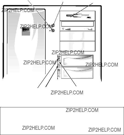
front of computer
Figure
NOTE: When following the text in this manual, assume that the location or direction relative to the system is as shown in Figure
Figure
CAUTION: To avoid possible data or file structure corruptions, the front- panel reset button should be used only when restarting the system with a key combination fails. Before using the reset button to initiate a hardware reset, close any open application programs and files if possible. If you are using

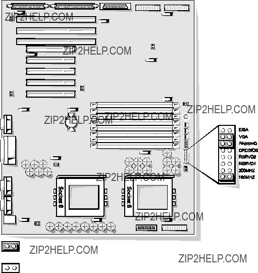
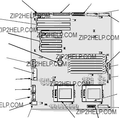
expansion slots 
system board
microprocessor sockets
cooling fan connectors (3) (cooling fans are located behind the air intake panel)
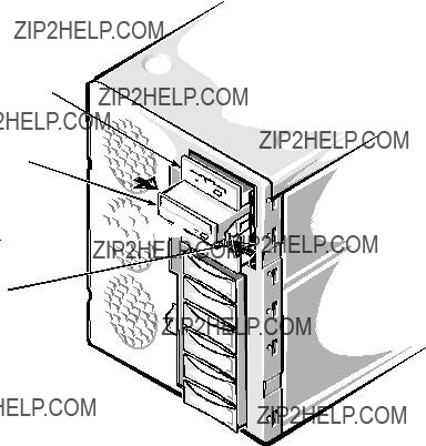
Figure
external drive bays (4)
control panel
internal drive bays (6)

air intake panel
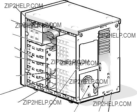
external drive bays (4)
diskette interface cable
SCSI interface connector
internal drive bays (6)
SCSI backplane board
SCSI power connector
server management connector 
control panel connector
power supply (optional)
Figure
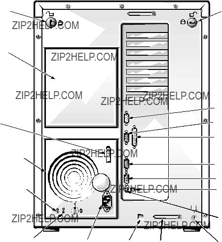
keylock
power supply (optional)
cable strain relief
power supply 
red LED 
green LED 
 AC power receptacle SMB connector
Figure
keylock
 video connector

parallel port connector
serial port 2 connector
serial port 1 connector
mouse connector
System Memory
The PowerEdge 4100 systems have a minimum of 64 MB of
The system board has eight
???Populate the DIMM sockets in order from DIMM A (upper) to DIMM H (lower).
???The DIMMs should be obtained from Dell to guarantee compatibility. All system memory operates at the speed of the slowest DIMM installed.
???DIMMs of both capacities can be installed in the system. However, the
The
See ???DIMMs??? in Chapter 4 for information on removing and replacing DIMMs.
Advanced Expansion Subsystem
The computer system offers advanced expansion subsystems that can support a mixture of traditional EISA expansion cards, Plug and Play ISA expansion cards, and PCI expansion cards. The EISA Configuration Utility, included with the system, provides a means of avoiding resource conflicts that might arise from such an arrangement.
After all legacy cards have been configured with the EISA Configuration Utility, the system automatically assigns required memory space, IRQ lines, and DMA channels to any installed Plug and Play ISA expansion cards and PCI expansion cards the next time the system is rebooted. Chapter 5, ???Using the EISA Config- uration Utility,??? in the Dell PowerEdge 4100/180 and 4100/200 Systems User???s Guide describes the EISA Configuration Utility and provides instructions for using it to configure the system.
The eight
Integrated Server Management
The system board contains integrated server management circuitry that moni- tors critical system voltages and temperatures, as well as the operation and speed of the system cooling fans. The integrated server management circuitry works in conjunction with the Intel LANDesk?? Server Management suite.
Video Controller
The video subsystem is built into the system board and consists of a
Maximum noninterlaced resolutions are 640 x 480 pixels with 16.7 million col- ors, 800 x 600 pixels with 65,536 colors, and 1024 x 768 pixels with 256 colors.
Integrated SCSI Controllers
A
A
SCSI
Six internal
NOTES: The externally accessible drive bays at the front of the computer are normally used for diskette drives,
Dell supports the drives it furnishes.
SCSI Configuration Guidelines
Although SCSI devices are installed essentially the same way as other devices, their configuration requirements are different. To configure your SCSI sub- system, follow the general guidelines offered in the following subsections.
SCSI ID Numbers
Each device attached to the 7860 Ultra/Narrow SCSI host adapter must have a unique SCSI ID number from 0 to 7. For additional SCSI addressing informa- tion, see Chapter 10, ???Installing Drives in the Internal Bays,??? in the Installation and Troubleshooting Guide.
When narrow SCSI devices are shipped from Dell, the default SCSI ID numbers are assigned as follows:
???The computer???s
???A SCSI
???A SCSI tape drive (if installed) is configured as SCSI ID 6.
NOTE: There is no requirement that SCSI ID numbers be assigned sequentially or that devices be attached to the cable in order by ID number.
Devices attached to the Ultra/Wide SCSI host adapter need no ID settings or ter- mination; ID settings and termination are handled automatically by the SCSI backplane.
Device Termination
SCSI logic requires that termination be enabled for the two devices at opposite ends of the SCSI chain and disabled for all devices in between. Therefore, regardless of whether you are installing internal or external devices, use the fol- lowing guidelines:
???A single SCSI device (such as the standard
???If two or more SCSI devices are installed, connect the devices as follows:
???Attach one of the devices to the end connector on the SCSI cable, and leave the terminator enabled on that device.
???The other end of the SCSI cable connects to the computer???s
???Disable the terminators on all other devices you attach to the cable.
The standard SCSI
See the documentation provided with the SCSI device for information on dis- abling the device???s terminator.

System Unit
The following subsections provide
System Power Supply
The
NOTE: The power supply produces DC voltages only under its loaded condi- tion. Therefore, when you measure these voltages, the DC power connectors must be connected to their corresponding power input connectors on the system board or drives.
.
Table
1Maximum continuous DC output power shall not exceed 500 W.
2VFP (volts flea power) ??? sometimes called ???standby power.???

Pin Assignments for the DC Power Connectors (Nonredun- dant Systems)
The
P2 
P1 
Figure
J12 (P2)
 J11 (P1)
J15 (P5)

 J14 (P4)
J13 (P3)
Figure

J11 (P1)
1
2
Pin 13 ??? PSON# should measure between +4 and +5 VDC except when the power button on the front panel is pressed, taking PSON# to its
Pin 5 ??? PWRGOOD should measure between +4 and +5 VDC when the power supply is on and oper- ating to indicate that all
Figure
System Overview

J12 (P2), J13 (P3),
J14 (P4)
Figure
+SW1
+12 VDC (red)
+3.3 VDC (orange) Fail LED cathode (red)
Good LED cathode (green)
6 7 8 9 10
J15 (P5)
1 2 3 4 5
Good LED anode (green)
Fail LED anode (red)
+5 VDC (red) +FAN_TACH (gray) +SW1
Figure

DC Power Distribution (Nonredundant System)
Figures
control panel
+5 VFP from SCSI backplane
Figure
System Overview

Pin Assignments for the DC Power Connectors (Redundant Systems)
The
PWR1
PWRFD
PWR2
PWR3
PWRSCSI (DDBP)
diagnostics port
Figure

NC_3INH
common (black)
POWER_GOOD (gray)
common (black)
+5 VFP (violet)
10 11 12 13 14 15 16 17 18
+3.3 VDC sense (orange)
NC_NRLED
PWR1
PWR_STAT_BIT (gray)
I 2C_SDA (gray)
I 2C_SCL (gray)
BAT_V (gray) PRES_DET (gray) NC_+12 sense
+5 VDC sense (red)
Figure
Figure
System Overview

PWRSCSI (DDBP)
Figure
+12 VDC (yellow) common (black) common (black) +5 VDC (red)
5 6 7 8 2
PWRFD
1 2 3 4 1
+5 VDC (red) common (black) common (black) +12 VDC (yellow)
1Wires 1 through 4 are connected to FD1 and FD2.
2Wires 5 through 8 are connected to FD3 and FD4.
Figure
DC Power Distribution (Redundant System)
Figures
control panel
+5 VFP from SCSI backplane
Figure
System Overview

System Board Layout
The subsections that follow provide
Figure
Main Memory
The eight DIMM sockets on the system board can accommodate combinations of 32- and
When reinstalling DIMMs, use the following guidelines:
???Install a DIMM in socket DIMM A before socket DIMM B, in socket DIMM B before socket DIMM C, and so on.
???If you are installing DIMMs of different sizes, install them in order of decreasing capacity, beginning with socket DIMM A.
???DIMMs need not be installed in pairs, but gold connectors are required. See ???DIMMs??? in Chapter 4 for information on removing and replacing DIMMs.
System Board Jumpers
Figure
System Overview

Table
Interrupt Assignments
DMA Channel Assignments
System Overview

Technical Specifications
Table
Microprocessor
Microprocessor type . . . . . . . . single or dual Intel Pentium Pro microprocessors
System chip set . . . . . . . . . . . . Intel Natoma 82440FX set
Data bus width . . . . . . . . . . . . 64 bits
Address bus width . . . . . . . . . 32 bits
Flash EPROM. . . . . . . . . . . . . 4 Mbits
Expansion Bus
Bus speed . . . . . . . . . . . . . . . . PCI: 30 MHz (180/60 processor); 33 MHz (200/66 processor);
EISA: 7.5 MHz (180/60 processor); 8.33 MHz (200/66 processor)
PCI
connectors. . . . . . . . . . . . . . . . five
EISA
connectors. . . . . . . . . . . . . . . . three
EISA
connector size . . . . . . . . . . . . . 198 pins
EISA
data width (maximum) . . . . . . 32 bits
PCI
connector size . . . . . . . . . . . . . 120 pins
PCI
data width (maximum) . . . . . . 32 bits

Table
System Clocks
System clock . . . . . . . . . . . . . . 60 or 66 MHz (matches external processor bus speed)
Diskette/communications
ports . . . . . . . . . . . . . . . . . . . . 24 MHz from the system clock
Memory
Architecture . . . . . . . . . . . . . .
DIMM sockets . . . . . . . . . . . . eight
DIMM capacities . . . . . . . . . . 32 and 128 MB, EDO mode
Standard RAM . . . . . . . . . . . . 64 MB
Maximum RAM . . . . . . . . . . . 1024 MB (1 GB)
BIOS address . . . . . . . . . . . . .
Drives
Externally accessible bays . . . four
Internally accessible bays . . . . six 1- to
System Board Connectors
Externally accessible:
Serial (DTE) . . . . . . . . . . . two
Server Management
(serial) . . . . . . . . . . . . . . . . one
Parallel . . . . . . . . . . . . . . . one
Video . . . . . . . . . . . . . . . . . one
Internally accessible:
Diskette drive . . . . . . . . . . one
Fan . . . . . . . . . . . . . . . . . . three
System Overview

Table
System Board Connectors (continued)
POWER1 . . . . . . . . . . . . . one
POWER2 . . . . . . . . . . . . . one
POWER3 . . . . . . . . . . . . . one
BACKPLANE SCSI1. . . . one
SCSI2
SMB BACKPLANE. . . . . one
SCSI Backplane Connectors
SCSI
sockets . . . . . . . . . . . . . . . . . . six
Video
Video type. . . . . . . . . . . . . . . .
Video memory . . . . . . . . . . . .
embedded PCI (see User???s Guide for specifications)
1 MB
Key Combinations
<Ctrl><Alt><Del> . . . . . . . . . . . .
<F2>. . . . . . . . . . . . . . . . . . . . . . . .
reboots the system (if running
starts System Setup program (during POST only)
Controls and Indicators
Reset control. . . . . . . . . . . . . . push button Power control . . . . . . . . . . . . . push button Power indicator. . . . . . . . . . . . green LED
Diskette drive access
indicator . . . . . . . . . . . . . . . . . green LED
SCSI
indicator . . . . . . . . . . . . . . . . . green LED

Table
Controls and Indicators (continued)
System Overview

Table
Environmental (continued)
Altitude:
Operating . . . . . . . . . . . . .
z
Chapter 2
Basic Troubleshooting
This chapter describes basic troubleshooting procedures that can help you diagnose a computer system problem. These procedures can often reveal the source of a problem or indicate the correct starting point for troubleshooting the system. (A brief explanation of how to load and start the system diagnostics is located near the end of this chapter.) Dell recommends that you perform the fol- lowing procedures in the order they are presented in this manual.
Initial User Contact
When you first contact a user who has a problem, ask the user to describe the problem and the conditions under which it occurs. A verbal description can often indicate the cause of a problem or else the appropriate troubleshooting procedure to use. After the user describes the problem, follow these steps:
1.Ask the user to back up any data on the
Appendix C, ???Maintaining the System,??? in the User???s Guide provides infor- mation about backing up data.
2.Ask the user to try to duplicate the problem by repeating the operations he or she was performing at the time the problem occurred.
Can the user duplicate the problem?
Yes. Proceed to step 3.
No. Proceed to the next section, ???External Visual Inspection.???
3.Observe the user to determine if he or she is making an error, such as typing an incorrect key combination or entering a command incorrectly.
Is the problem a result of user error?
Yes. Instruct the user in the proper procedure, or direct him or her to the appropriate user documentation for the correct procedure.
No. Proceed to the next section, ???External Visual Inspection.???
External Visual Inspection
The external visual inspection consists of a quick inspection of the exterior of the computer, the monitor, the keyboard, any peripherals, and cables. While per- forming the visual inspection, make any necessary corrections. To perform the external visual inspection, follow these steps:
1.Turn off the computer, the monitor, and all peripherals.
2.Verify that all power cables are properly connected to the computer, the monitor and peripherals, and their power sources.
3.Verify that the keyboard and mouse interface cables are firmly attached to the proper connectors on the back of the computer.
For a
For a serial mouse, the mouse interface cable must be attached to one of the serial port connectors, and its captive screws must be secure enough to ensure a firm connection.
4.Verify that any devices attached to the serial and parallel port connec- tors are properly connected.
Each of the serial and parallel interface cables must be attached to an appro- priate connector on the back of the computer as well as to the interface connector on the device. The captive screws that secure these connectors at each end of the interface cable must be secure enough to ensure a firm connection.
5.Verify that the video interface cable is firmly attached to the connector on the I/O panel and to the connector on the back of the monitor.
For proper connection of the video interface cable, see the documentation for the monitor.
6.Inspect all external monitor controls for any obvious damage or improper settings.
For proper settings of the video monitor controls, see the documentation for the monitor.
7.Inspect the keyboard to ensure that no keys are sticking.
If one or more keys are sticking, it may be necessary to replace the keyboard.
8.Inspect the exterior of the computer, including all controls and indica- tors, and all
Does the inspection reveal any problems?
Yes. Proceed to the appropriate procedure in Chapter 4, ???Removing and Replacing Parts.???
No. Proceed to the next section, ???Observing the Boot Routine.???
Observing the Boot Routine
After you have performed an external visual inspection as described in the pre- vious section, you should boot the system and, while the boot routine is running, observe the system for any indications of problems.
NOTE: Most of the steps in this procedure require observation of system func- tions and indications, some of which can occur simultaneously. It may be necessary to reboot the system several times in order to complete all of these steps.
To observe problem indications during the boot routine, follow these steps:
1.If the system is off, turn on all peripherals and the computer. Insert the Dell Server Assistant CD into the
2.Check the power supply fans.
Do the fans run normally?
NOTE: The center fan is normally off, unless another fan has failed or is unplugged, or the temperature of the computer is too high.
Yes. Proceed to step 3.
No. Troubleshoot the system power supply.
3.Watch the Num Lock, Caps Lock, and Scroll Lock indicators on the
Do these indicators flash on and off within approximately 10 seconds after the boot routine starts?
Yes. Proceed to step 4.
No. Troubleshoot the system power supply. If the troubleshooting procedure indicates that the system power supply is operational, troubleshoot the memory.
4.During the boot routine, observe the computer for any of the following:
???Beep codes: A beep code is a series of beeps that indicates an error con- dition. If the system emits a beep code, see Table
NOTE: The system beeps once during the boot routine. This single beep is normal and is not a beep code.
???System error messages: These messages can indicate problems or pro- vide status information. If a system error message is displayed, see Table
???
5.Observe the monitor screen for the Dell Server Assistant Menu.
Does the menu appear?
Yes. See ???Running the System Diagnostics??? found later in this chapter.
No. Proceed to the next section, ???Internal Visual Inspection.???
Internal Visual Inspection
CAUTION: Before you proceed with the internal visual inspection described in this section, ensure that the user has saved all open files and exited all open application programs if possible.
A simple visual inspection of a computer???s interior hardware can often lead to the source of a problem, such as a loose expansion card, cable connector, or mounting screw. When you perform the visual inspection, refer to ???System Features??? in Chapter 1 to locate components in the inspection procedure.
To perform the internal visual inspection, follow these steps:
1.Turn off the system, including any attached peripherals, and disconnect all the AC power cables from their power sources.
2.Remove the left computer cover.
3.Verify that all DIMMs and expansion cards as well as the micro- processor(s) and battery are fully seated in their sockets or connectors.
WARNINGS: The microprocessor can get extremely hot. Be sure the chip has had sufficient time to cool before you touch it.
To maintain proper air flow and prevent the system from overheat- ing, each power supply bay must have either a power supply or the power closeout panel installed.
To ensure that the chips are fully seated in their sockets, press firmly on the top of each chip.
To reseat a microprocessor, first remove it from its socket and then reinstall it as described in ???Microprocessor and Heat Sink??? in Chapter 4.
To reseat a DIMM, remove it from its socket and reinstall it as described in ???DIMMs??? in Chapter 4.
If you need to reseat an expansion card, use a
4.Verify that all jumpers are set correctly.
For information about these jumpers, see ???System Board Jumpers??? in Chap- ter 1.
5.Check all cable connectors inside the computer to verify that they are firmly attached to their appropriate connectors.
6.Reinstall the computer cover.
7.Reconnect the computer and any attached peripherals to their power sources, and turn them on.
Does the problem appear to be resolved?
Yes. No further steps are necessary. Terminate the procedure.
No. Proceed to the next section, ???Eliminating Resource Conflicts,??? and to ???Getting Help??? found later in this chapter.
Eliminating Resource Conflicts
Devices within the computer may require dedicated memory spaces, interrupt levels, or DMA channels, all of which must be allocated during installation of the devices. Because a device may be installed at a different time, it is possible that the same resource is assigned to two or more devices.
Resource conflicts can result in disorderly or erratic system operation or failure of the system to operate at all. If you suspect that resource conflicts might exist, check the system and reassign the resources as necessary.
Running the System Diagnostics
The system diagnostics (included on the Dell Server Assistant CD) contains tests that aid in troubleshooting all major components of the computer system.
To start the diagnostics, insert the CD into the
Restarting the computer causes the Dell Server Assistant logo screen to appear on the monitor screen, followed by a screen containing icons of the options available. Selecting the Run System Utilities icon brings up a screen with the diagnostics icon. Before the Dell Server Assistant loads, a program tests the portion of main memory (RAM) required for loading the diagnostics. If a main memory error is detected, a message telling you which DIMM has failed appears on the screen.
If no errors are found in main memory, and the Dell Server Assistant loads, select the Run System Utilities icon. Then select the Run System Diagnostics icon by pressing <Enter>. The Diagnostics Menu appears, allowing you to choose the following options or exit to
???Run All Tests ??? Runs all tests for a thorough check of the system
???Run Quick Tests ??? Runs selected tests from all test groups to quickly locate a failure or to indicate where further testing is needed to isolate a failure
???Run Specific Tests ??? Tests a particular area or subsystem
Getting Help
If none of the troubleshooting procedures in this chapter or the tests in the system diagnostics reveals the source of the problem or leads to the proper trou- bleshooting steps for determining the source of the problem, call Dell for technical assistance. For instructions, see Chapter 11, ???Getting Help,??? in the
Installation and Troubleshooting Guide.

Chapter 3
Beep Codes and Error Messages
This chapter describes beep codes and system error messages that can occur during system
If a faulty system does not emit beep codes or display system error messages to indicate a failure, you should use the
POST Beep Codes
If the monitor cannot display error messages during the POST, the system may emit a series of beeps that identifies the problem or that can help you identify a faulty component or assembly. Table
When the system emits a beep code, record the code and then find it in
Table
Table

Table

System Error Messages
Table
Table
Run System Setup pro- gram to restore your system configuration.

Table
Table
Power supply
failed
System back- plane firm- ware download failed
Check server- management bus cable connections to system board (labeled ???SMB BACKPLANE???) and SCSI backplane (labeled ???SMB???). Turn off and then restart system.

Chapter 4
Removing and Replacing Parts
This chapter provides procedures for removing the components, assemblies, and subassemblies in the system unit. Unless otherwise noted, each procedure assumes the following:
???You have performed the steps in ???Precautionary Measures??? found later in this chapter.
???You have removed the computer covers.
???You can replace or reinstall a part by performing the removal procedure in reverse order unless additional information is provided.
Recommended Tools
Most of the procedures in this chapter require the use of one or more of the fol- lowing tools:
???Small
???Wide
???Number 1 and number 2
???
???
???Tweezers or
???Small plastic scribe
Also, use a wrist grounding strap as explained in the next section, ???Precaution- ary Measures.???

Precautionary Measures
Before you perform any of the procedures in this chapter, take a few moments to read the following warning for your personal safety and to prevent damage to the computer system from ESD.
WARNING FOR YOUR PERSONAL SAFETY AND PROTECTION OF THE EQUIPMENT: Only service technicians trained by Dell should perform the following procedures. Before you start to work on the com- puter, perform the following steps in the sequence listed.
1.Turn off the computer and any attached peripherals.
2.Disconnect the computer and any attached peripherals from their power sources to reduce the potential for personal injury.
3.Disconnect any communications cables.
4.Wear a wrist grounding strap, and clip it to an unpainted metal sur- face, such as a part of the back panel, on the computer chassis.
If a wrist grounding strap is not available, touch the fan guard or some other unpainted metal surface on the back of the computer to discharge any static charge from your body.
Computer Covers
screw (6)
Figure

To remove a computer cover, follow these steps:
1.Turn the cover???s keylocks on the back panel of the computer to the unlocked position (see Figure
keylock (2)
Figure
2.Loosen the three screws along the back edge of the cover (see Figure
3.Slide the cover toward the back of the computer an inch or so. Then grasp the top of the cover at both ends, and lift it straight away from the chassis.

Front Bezel
tab (4)
front bezel
Figure
To remove the front bezel, follow these steps:
1.Remove the computer covers.
2.Release the two tabs on each side of the bezel.
3.Slide the front bezel toward the front of the computer.

Drives
Figure
DC power cable
diskette/tape drive interface cable
diskette drive interface connector (FLOPPY)
SCSI connector (SCSI2
system board
SCSI connector
(BACKPLANE SCSI1)
 SCSI2
SCSI2
SCSI
SCSI backplane board
SCSI interface cable
Figure

tab (2)
latch (2) 
back of the front bezel
Figure
To remove a
1.Remove the front bezel.
2.From the back of the front bezel, press against the center of the insert until the tabs come loose from the bezel.
3.Pull the insert out of the bezel.
To replace a
Externally Accessible Drives


 position for optional


 drive
drive 


Figure
All of the externally accessible drives have
1.Disconnect the DC power cable and the interface cable from the back of the drive.
Be sure to record the power connector number and interface cable connector identification.
2.Press inward (toward center of drive) on the two

3. Remove the
Figure
4.If the drive is a SCSI drive, record the setting of the SCSI address jumpers and SCSI bus termination jumper.
Some drives use an adapter between the SCSI cable and the drive connector. Check the back of the old drive for an adapter. If present, remove the adapter and retain it for use on the new drive.
When reinstalling the SCSI drive, set the SCSI address jumpers and the SCSI bus termination jumpers to the settings you recorded.
 drive bay
plastic drive handle
Figure
The
NOTES: Wait 20 seconds for the
1.If a PowerEdge Expandable RAID Controller host adapter card is installed in the computer, wait until the three indicators are off, and then proceed to Step 2 (refer to Chapter 6, ???Installing SCSI
2.Release the carrier by pulling down on the plastic drive handle.
3.Slide the drive carrier toward the front of the computer until it is free of the drive bay.
4.Turn the drive carrier over, and place it on a flat work surface.

connector
carrier
screw (4)
Figure
5.Remove the four mounting screws that attach the
6.Disconnect the
CAUTION: When disconnecting the
After you replace the drive and reinstall the carrier in the bay, turn on the sys- tem. The online indicator (green) lights, indicating power is being supplied to the

SCSI Backplane Board
thumb screw
hook (10)
SCSI backplane board
Figure
To remove the SCSI backplane board, follow these steps:
1.Disconnect the
2.Disconnect all cables from the SCSI backplane board.
3.Unscrew the thumb screw.
4.Disengage the board from the ten hooks holding the board to the com- puter chassis, and lift the board away from the computer.
An insulator (similar to the one for the

Power Supply
The computer may have one or two power supplies.
power closeout panel
 power supply (optional)
power supply
cable strain relief
insertion screw
AC power cable connector
locking switch
Figure
To remove a power supply, follow these steps:
WARNING: In a redundant system, you can remove and replace a power supply without turning off the system. When doing so, be careful not to touch any of the connectors on the
CAUTION: To maintain proper airflow and prevent the system from overheating, each power supply bay must have either a power supply or a power closeout panel installed.
1.Turn the locking switch on the power supply to the Off position (marked by a ???0???).
2.Unhook the cable strain relief to free the AC power cable.
3.Disconnect the AC power cable from the power outlet; then disconnect the other end of the cable from the power supply.
4.Turn the insertion screw counterclockwise to release the power supply.
5.Slide the power supply out of the chassis.
To replace a power supply, perform these steps in reverse order.

cables
thumb screw
power supply (2)

Figure
Systems)
To remove a
WARNING: Disconnect both power supplies from their AC power source to prevent the possibility of getting shocked.
1.Disconnect the power supplies from the
2.Disconnect all cables from the
3.Unscrew the thumb screw.
4.Disengage the board from the eleven hooks holding it to the computer chassis, and then lift the board away from the computer.
Removing and Replacing Parts

Power Connector Panel
power supply
 retainer screw
power connector panel cables (5)
power connector panel
hook slots (4)
Figure
Systems)
To remove the power connector panel, follow these steps:
1.Disconnect the power supply from the power connector panel by sliding the power supply toward the back of the computer approximately
1 inch.
2.Disconnect all power connector panel cables (from the system board, the SCSI backplane board, and so forth).
3.Unscrew the retainer screw.
4.Disengage the panel from the four hooks holding it to the computer chassis, and then lift the panel away from the computer.

Control Panel
screw 
control panel
connector BP_to_CP
Figure
To remove the control panel, follow these steps:
1.Remove the screw holding the control panel to the chassis.
2.Disconnect the cable from connector BP_to_CP.
3.Disengage the panel from the four hooks holding the panel to the computer chassis, and lift the panel away from the computer.
Removing and Replacing Parts
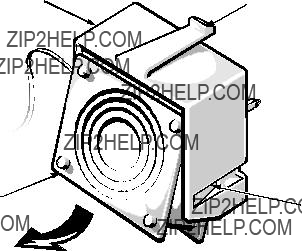
Cooling Fans
Figure
To remove a cooling fan, follow these steps:
NOTES: This procedure can be performed with the computer turned on.
The middle fan is normally turned off by server management; this fan is turned on only if one of the other fans fails.
1.Remove the left computer cover.
2.Disconnect the cooling fan???s power cable from its respective FAN con- nector on the system board.
3.Press down the catch on the fan carrier, and remove the fan carrier from the chassis.
4.Remove the cooling fan from the fan carrier by releasing the two fan retention tabs inside the carrier.
System Board Components
The subsections that follow contain procedures for removing system board components.
Figure
Removing and Replacing Parts

Expansion Cards
retaining screw
expansion card
locking card guide
Figure
To remove an expansion card, follow these steps:
1.Remove the left computer cover.
2.Disconnect any cables connected to the expansion card.
3.Remove the retaining screw from the
4.If the card is a
5.Grasp the expansion card by its corners, and carefully remove it from the
DIMMs
DIMM
securing clip (2)
2.
1.
Figure
To remove a DIMM, push outward on the DIMM socket???s securing clips until the DIMM is released from its socket. Then lift the DIMM away from the socket.
DIMM
 securing clip (2)
2.
1.
Figure
To replace a DIMM, push outward on the securing clips at each end of the socket until they snap open. Orient the DIMM to the socket, and press the DIMM straight down into the socket slot until the securing clips snap into place around both ends of the DIMM.
Removing and Replacing Parts

Microprocessor and Heat Sink
clip
heat sink
thermal pad
(bonded to heat sink)
microprocessor
microprocessor socket


front tab
Figure
The computer may have two microprocessors. To remove a microprocessor and heat sink, follow these steps:
1.Remove the microprocessor securing clip from the microprocessor/heat sink assembly.
WARNING: The microprocessor chip can get extremely hot during system operations. Be sure the chip has had sufficient time to cool before touching it.
Press down on the folded part of the clip with a small screwdriver to release the clip (see Figure

microprocessor securing clip hooks over tabs on socket (front and back)
microprocessor socket
Figure
2.Remove the heat sink.
3.Push outward and then upward on the microprocessor release lever to rotate the lever to its fully vertical position.
CAUTION: Be careful not to bend any of the pins when removing the microprocessor chip from its socket. Bending the pins can per- manently damage the microprocessor chip.
microprocessor chip
microprocessor socket
release lever
Figure
Removing and Replacing Parts
4. Lift the microprocessor out of its socket.
To install the replacement microprocessor/heat sink assembly, ensure that the micro- processor release lever is in its fully vertical position to allow the microprocessor pins to easily slip into the socket. When the microprocessor/heat sink assembly is in place, rotate the microprocessor release lever to its horizontal position. Hook the micro- processor securing clip over the socket tab nearest the front of the system board, and then snap it over the tab on the back of the socket.
(gold finger and bevel)
Figure
NOTE: Pin 1 on the microprocessor is located on the corner with the largest bevel. The
If you are installing a new microprocessor and heat sink, place the thermal interface pad that comes with the replacement microprocessor between the microprocessor and the heat sink before reinstalling the securing clip.
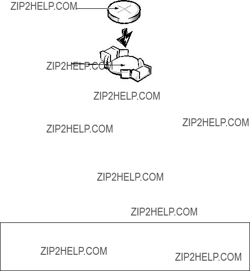
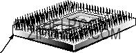
System Battery
battery
BATTERY socket
Figure
To remove the system battery, follow these steps:
1.If possible, enter the System Setup program, and make a printed copy of the system setup screens.
2.Remove the left computer cover.
See ???Computers Covers??? found earlier in this chapter.
3.Remove the battery.
Pry the battery out of its socket with your fingers or with a blunt, noncon- ducting object, such as a plastic screwdriver.
To replace the system battery, follow these steps.
WARNING: The new battery can explode if installed incorrectly. Be careful to replace the battery as instructed in the following procedure. In addition, replace the old battery only with one of the same or an equiva- lent type, as recommended by the manufacturer. Discard the old battery according to the manufacturer???s instructions.
1.Orient the new battery with the ???+??? facing up. Insert the battery into its socket, and snap it into place.
2.Start the System Setup program, and reset the Time and Date categories.
Also, compare the system configuration information with the copy of the system configuration settings you made in step 1 of the removal procedure. Restore any system configuration information that was lost while replacing the battery.
Removing and Replacing Parts

System Board
system board
slot (13)
screw
Figure
To remove the system board, follow these steps:
1.Disconnect all cables from their connectors at the back of the system unit.
2.Remove all expansion cards.
3.Disconnect all cables from the system board.
4.Remove the system board as follows:
a.Remove the screw that secures the system board to the vertical wall of the computer chassis.
b.Slide the system board toward the front of the computer approximately 1/2 inch to release the board from the 13 slots in the computer chassis.
c.Lift the system board out of the computer.
If you are replacing a system board, remove the DIMMs, the microprocessor(s), and the expansion card from the old system board and install them on the replacement board.

Appendix A
System Setup Program
This appendix describes the System Setup program, which is used to set or change the system configuration information stored in NVRAM on the system board.
To enter the System Setup program, press <F2> during the
If you wait too long, the operating system begins to load into memory and you cannot enter the System Setup program. Let the system complete the load operation; then shut down the system and try again.
NOTE: To ensure an orderly system shutdown, consult the documentation that accompanied the operating system.
System Setup Screens
The System Setup program is a
???Main menu ??? Provides settings for the basic system configuration
???Advanced menu ??? Provides detailed settings for some system features
???Security menu ??? Provides settings for password status, diskette access, virus check reminder, and system backup reminder
???Exit menu ??? Provides settings for saving and loading the configurations and options
In addition to the initial menu selections, some selections have submenus. These selections are identified by an arrow to the left of the selection.
Screen Conventions
Information on the System Setup screens is organized in four boxed areas (see Figure
???Title box ??? Contains information about the system and menu selections
???Configuration options and system data box ??? Lists configuration categories (left column) and settings or information (right column)
???Help box ??? Displays
???Key functions box ??? Lists the System Setup keys and their functions

Key Functions
Table
Table

Screen Color Combinations
In addition to its text, a field???s color identifies the type of information it con- tains, as follows:
???Black on cyan ??? Headers and footers, including the title box at the top of the screen and the key functions box at the bottom of the screen.
???Blue on white ??? Configuration information that cannot be changed by the user, such as category titles.
???Black on white ??? Fields that can be changed by the user, but are not selected. Also used for help messages.
???Bright white on white ??? The highlight color for a category title that is selected. Also used to highlight the function keys in the key functions box.
???White on black ??? The highlight color for an input field that is selected.
Main Menu
key functions box
Figure

Table
Boot Options Submenu
Determines the order of drives from which the system tries to boot.
Figure
Table

Advanced Menu
Figure

Security Menu
Figure

Table

Exit Menu
Figure

Table
System Setup Program
Index
A
AC power receptacle about,
location on I/O panel,
B
battery connector,
removing and replacing,
BATTERY connector,
beep codes,
boot routine
observing when troubleshooting,
C
cables
DC power,
carrier,
computer
back/right side internal view,
technical specifications,
configuration guidelines SCSI drives,
configuration jumpers
location on system board,
connectors
location on system board,
control panel connector,
cover, system unit removal,
D
DC power about,
connectors,
pin assignments,
DC power distribution nonredundant system,
diagnostics,
DIMMs
about,
ECC,
location on system board,
socket population rules,
diskette drive illustrated,
diskette/tape drive interface connector,
Index 1
DREQ line assignments,
drive bays external,
drives about,
illustrated,
SCSI configuration guidelines,
SCSI termination jumpers,
E
ECC,
EISA expansion cards,
EISA
error messages, system list of,
expansion cards
slots,
expansion subsystem,
external visual inspection,
externally accessible drives removal,
F
FAN connectors,
fan connectors,
fatal error messages,
FLOPPY connector,
front bezel removal,
H
help, getting,
I
indicator card removal,
initial procedures,
initialization error messages,
integrated features SCSI controllers,
interrupt assignments list of,
ISA expansion cards,
J
jumpers
list of,
K
KEYBOARD connector,
keyboard connector location on I/O panel,
location on system board,
2 Dell PowerEdge 4100/180 and 4100/200 Systems Service Manual
M
memory
main,
system,
messages, error,
microprocessor release lever,
removal,
sockets,
microprocessor cooling fans removal,
MONITOR connector,
MOUSE connector,
mouse connector
location on I/O panel,
P
padlock,
PARALLEL connector,
parallel port connector location on I/O panel,
location on the system board,
PCI expansion cards,
PCI
Plug and Play ISA expansion cards,
POST beep codes,
power
AC power receptacle,
switch,
power connector plate removal,
power distribution diagram nonredundant system,
power supply about,
connector configuration,
DC voltage ranges,
voltage output ranges,
POWER1 connector,
POWER2 connector,
removal,
precautions,
PROCESSOR1 connector,
PROCESSOR2 connector,
R
REMOTE connector,
reset button
location on I/O panel,
resource conflicts eliminating,
S
SCSI BACKPLANE connector,
SCSI
SCSI connectors,
SCSI controllers, integrated,
SCSI devices
ID numbers,
SCSI
SCSI
SCSI ID numbers,
SERIAL connectors,
Index 3
serial port connectors location on I/O panel,
location on system board,
location on system board,
SMB BACKPLANE connector,
sockets battery,
DIMM,
specifications, technical,
subsystems
advanced expansion,
system board components,
removing and replacing,
system error messages list of,
system features,
system power supply,
System Setup program advanced menu,
boot options submenu,
key functions,
screen color combinations,
starting,
system specifications,
system unit cover,
T
technical specifications,
termination jumpers SCSI drives,
troubleshooting
boot routine, interpreting,
initial user contact,
U
Ultra/Narrow SCSI host adapter connector,
Ultra/Wide SCSI host adapter connector, 4-
17
user contact, initial,
V
video connector
location on I/O panel,
video controller, integrated,
visual inspection external,
4 Dell PowerEdge 4100/180 and 4100/200 Systems Service Manual