Dell??? Vostro??? 3700 Service Manual
Working on Your Computer
Specifications
Removing and Replacing Parts
System Setup
Diagnostics
Notes, Cautions, and Warnings
NOTE: A NOTE indicates important information that helps you make better use of your computer.
CAUTION: A CAUTION indicates potential damage to hardware or loss of data if instructions are not followed.
WARNING: A WARNING indicates a potential for property damage, personal injury, or death.
If you purchased a Dell??? n Series computer, any references in this document to Microsoft?? Windows?? operating systems are not applicable.
Information in this document is subject to change without notice.
?? 2010 Dell Inc. All rights reserved.
Reproduction of this material in any manner whatsoever without the written permission of Dell Inc. is strictly forbidden.
Trademarks used in this text: Dell, the DELL logo, and Vostro are trademarks of Dell Inc.; Intel and Core are either trademarks or registered trademarks of Intel Corporation; Microsoft, Windows, Windows Vista, and the Windows Vista start button are either trademarks or registered trademarks of Microsoft Corporation in the United States and/or other countries; Bluetooth is a registered trademark of Bluetooth SIG, Inc.
Other trademarks and trade names may be used in this document to refer to either the entities claiming the marks and names or their products. Dell Inc. disclaims any proprietary interest in trademarks and trade names other than its own.
Back to Contents Page
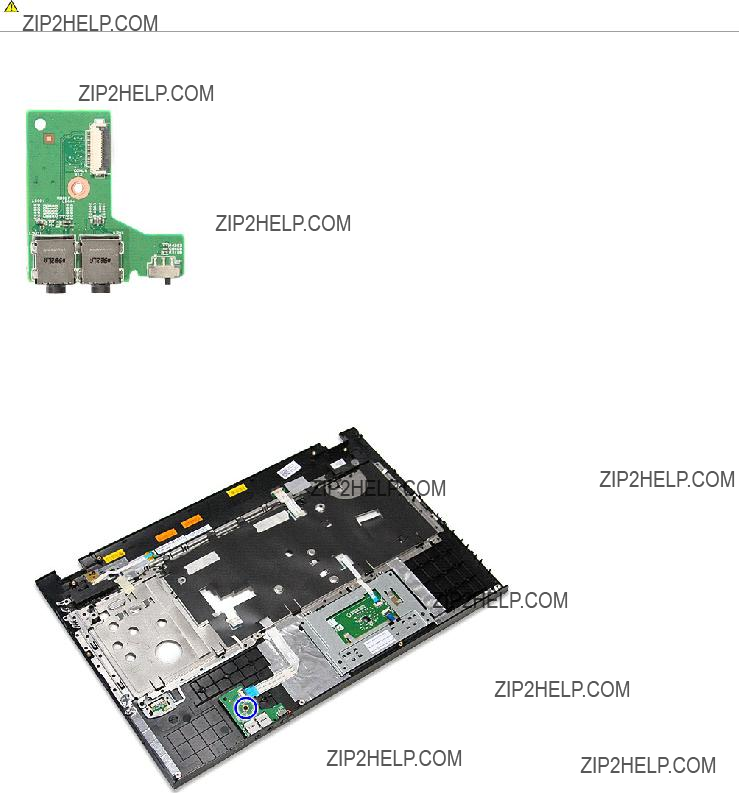
Audio Board
Dell??? Vostro??? 3700 Service Manual
WARNING: Before working inside your computer, read the safety information that shipped with your computer. For additional safety best practices information, see the Regulatory Compliance Homepage at www.dell.com/regulatory_compliance.
Removing the Audio Board
1.Follow the procedures in Before Working Inside Your Computer.
2.Remove the battery.
3.Remove the base cover.
4.Remove the hard drive assembly.
5.Remove the optical drive.
6.Remove the keyboard.
7.Remove the palm rest.
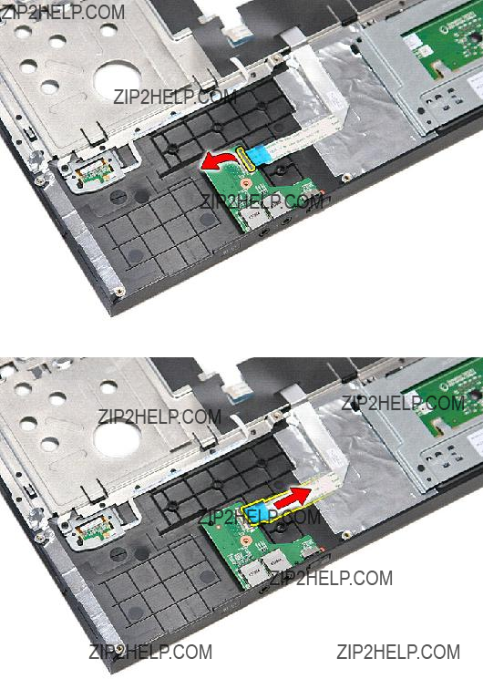
8.Remove the screw that secures the audio board to the palm rest.
9. Open the clip that secures the audio board cable to its connector on the audio board.
10.Disconnect the audio board cable from its connector on the audio board.
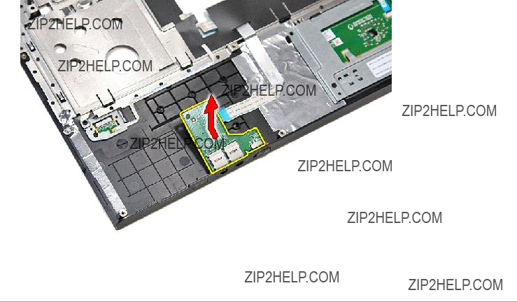
11. Lift the audio board up and away from the computer.
Replacing the Audio Board
To replace the audio board, perform the above steps in reverse order.
Back to Contents Page
Back to Contents Page
Base Cover
Dell??? Vostro??? 3700 Service Manual
WARNING: Before working inside your computer, read the safety information that shipped with your computer. For additional safety best practices information, see the Regulatory Compliance Homepage at www.dell.com/regulatory_compliance.
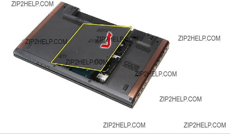
Removing the Base Cover
1.Follow the procedures in Before Working Inside Your Computer.
2.Remove the battery.
3.Remove the screws that secure the base cover to the computer.
4. Lift up the base cover and remove it from the computer.
Replacing the Base Cover
To replace the base cover, perform the above steps in reverse order.
Back to Contents Page
Back to Contents Page
Battery
Dell??? Vostro??? 3700 Service Manual
WARNING: Before working inside your computer, read the safety information that shipped with your computer. For additional safety best practices information, see the Regulatory Compliance Homepage at www.dell.com/regulatory_compliance.
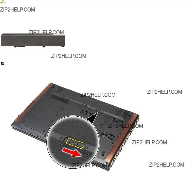
Removing the Battery
NOTE: You may need to install Adobe?? Flash?? Player from Adobe.com in order to view the illustrations below.
1.Follow the procedures in Before Working Inside Your Computer.
2.Flip the computer over.
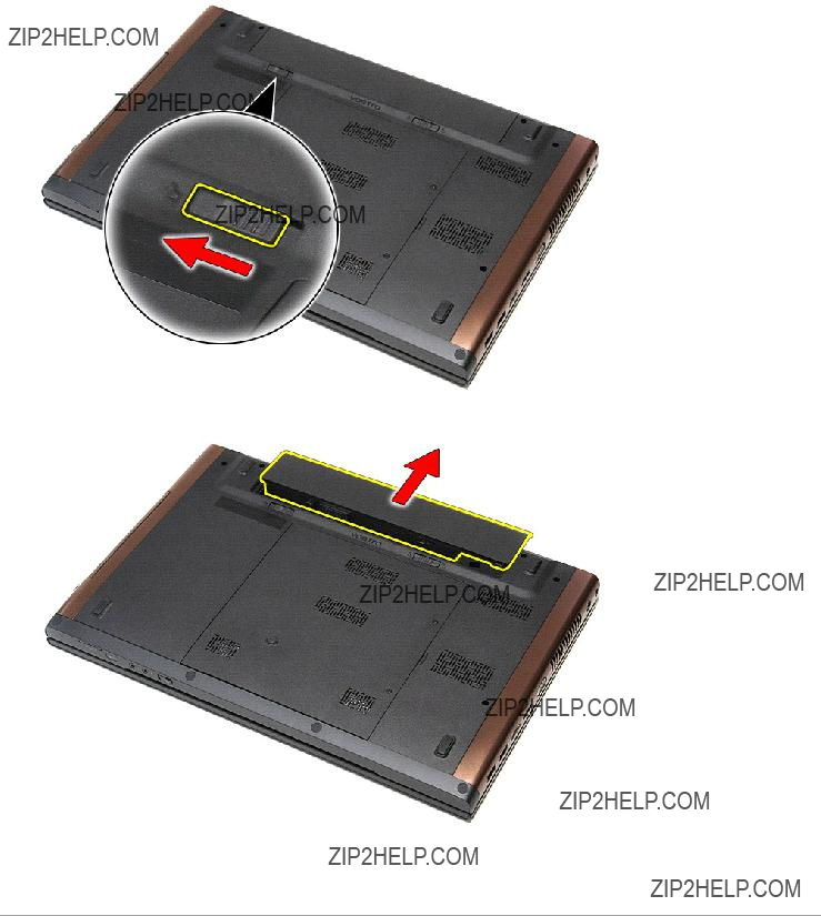
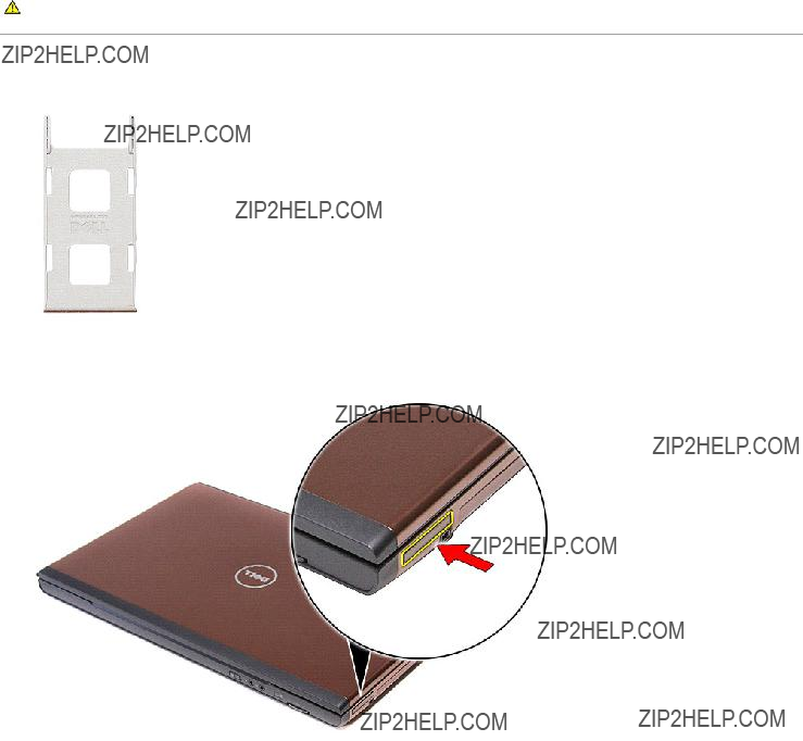
3.Slide the battery release latch to the unlock position.
4. Slide the other battery release latch to the unlock position.
5. Slide the battery and remove it from the computer.
Replacing the Battery
To replace the battery, perform the above steps in reverse order.
Back to Contents Page
Back to Contents Page
System Setup
Dell??? Vostro??? 3700 Service Manual
Overview
Entering System Setup
System Setup Screens
System Setup Options
Overview
Use System Setup as follows:
???To change the system configuration information after you add, change, or remove any hardware in your computer
???To set or change a user-selectable option such as the user password
???To read the current amount of memory or set the type of hard drive installed
Before you use System Setup, it is recommended that you write down the System Setup screen information for future reference.
CAUTION: Unless you are an expert computer user, do not change the settings for this program. Certain changes can cause your computer to work incorrectly.
Entering System Setup
1.Turn on (or restart) your computer.
2.When the blue DELL??? logo is displayed, you must watch for the F2 prompt to appear.
3.Once this F2 prompt appears, press <F2> immediately.
NOTE: The F2 prompt indicates that the keyboard has initialized. This prompt can appear very quickly, so you must watch for it to display and then press <F2>. If you press <F2> before you are prompted, this keystroke will be lost.
4.If you wait too long and the operating system logo appears, continue to wait until you see the Microsoft?? Windows?? desktop. Then, shut down your computer and try again.
System Setup Screens
Menu ??? Appears on top of the System Setup window. This field provides a menu to access the System Setup options. Press < Left Arrow > and < Right Arrow > keys to navigate. As a Menu option is highlighted, the Options List lists the options that define the hardware installed on your computer.
Use the following keys to navigate through the System Setup screens:
Main
The Main tab lists out the primary hardware features of the computer. The table below defines the function of each option.
Main
Advanced
The Advanced tab allows you to set various functions that affect the performance of the computer. The table below defines the function of each option and its default value.
Advanced
System Configuration
Security
The Security tab displays the security status and allows you to manage the security features of the computer.
Security
Boot
The Boot tab allows you to change the boot sequence.
Exit
This section allows you to save, discard, and load default settings before exiting from System Setup.
Back to Contents Page
Back to Contents Page
Bluetooth Card
Dell??? Vostro??? 3700 Service Manual
WARNING: Before working inside your computer, read the safety information that shipped with your computer. For additional safety best practices information, see the Regulatory Compliance Homepage at www.dell.com/regulatory_compliance.
Removing the Bluetooth Card
1.Follow the procedures in Before Working Inside Your Computer.
2.Remove the battery.
3.Remove the base cover.
4.Remove the hard drive.
5.Remove the optical drive.
6.Remove the keyboard.
7.Remove the palm rest.
8.Remove the audio board.
9.Lift the Bluetooth?? card up and away from the audio board.
Replacing the Bluetooth Card
To replace the Bluetooth card, perform the above steps in reverse order.
Back to Contents Page
Back to Contents Page
Camera
Dell??? Vostro??? 3700 Service Manual
WARNING: Before working inside your computer, read the safety information that shipped with your computer. For additional safety best practices information, see the Regulatory Compliance Homepage at www.dell.com/regulatory_compliance.
Removing the Camera
1.Follow the procedures in Before Working Inside Your Computer.
2.Remove the battery.
3.Remove the base cover.
4.Remove the hard drive.
5.Remove the optical drive.
6.Remove the wireless local area network (WLAN) card.
7.Remove the keyboard.
8.Remove the palm rest.
9.Remove the display assembly.
10.Remove the display bezel.
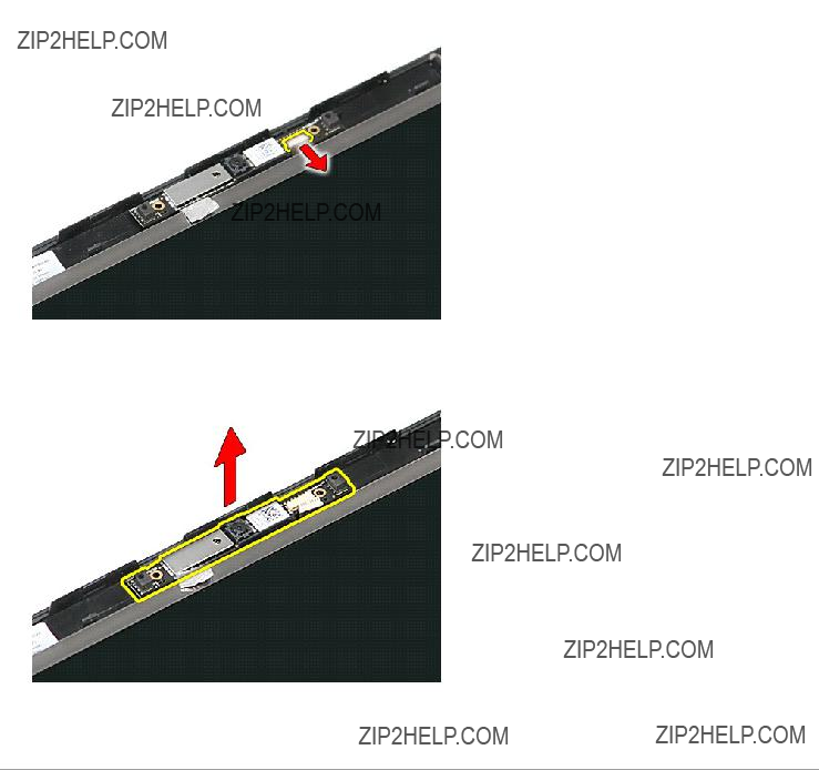
11.Remove the tape that secures the camera to the display assembly.
12. Disconnect the camera cable from the display assembly.
13. Lift the camera up and away from the computer.
Replacing the Camera
To replace the camera, perform the above steps in reverse order.
Back to Contents Page
Back to Contents Page
Coin-Cell Battery
Dell??? Vostro??? 3700 Service Manual
WARNING: Before working inside your computer, read the safety information that shipped with your computer. For additional safety best practices information, see the Regulatory Compliance Homepage at www.dell.com/regulatory_compliance.
Removing the Coin-Cell Battery
1.Follow the procedures in Before Working Inside Your Computer.
2.Remove the battery.
3.Remove the base cover.
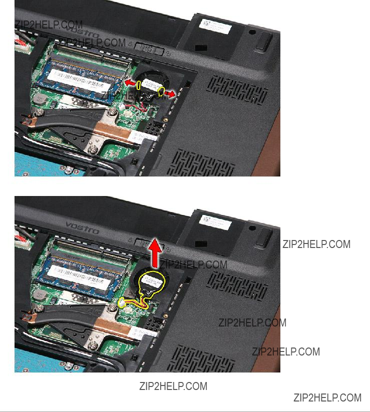
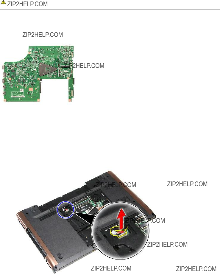
4.Disconnect the coin-cell battery cable from the system board.
5. Gently pry the tabs that secure the coin-cell battery to the system board away from the coin-cell battery.
6. Lift up the coin-cell battery and remove it from the computer.
Replacing the Coin-Cell Battery
To replace the coin-cell battery, perform the above steps in reverse order.
Back to Contents Page
Back to Contents Page
Diagnostics
Dell??? Vostro??? 3700 Service Manual
Device Status Lights
Battery Status Lights
Battery Charge and Health
Keyboard Status Lights
LED Error Codes
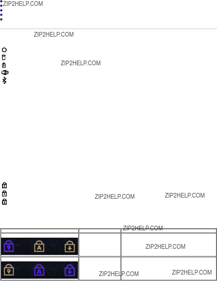
Device Status Lights
Turns on when you turn on the computer and blinks when the computer is in a power management mode.
Turns on when the computer reads or writes data.
Turns on steadily or blinks to indicate battery charge status.
Turns on when wireless networking is enabled.
Turns on when a card with Bluetooth?? wireless technology is enabled. To turn off only the Bluetooth wireless technology function, right-click the icon in the system tray and select Disable Bluetooth Radio.
Battery Status Lights
If the computer is connected to an electrical outlet, the battery light operates as follows:
???Alternately blinking amber light and blue light ??? An unauthenticated or unsupported non-Dell AC adapter is attached to your laptop.
???Alternately blinking amber light with steady blue light ??? Temporary battery failure with AC adapter present.
???Constantly blinking amber light ??? Fatal battery failure with AC adapter present.
???Light off ??? Battery in full charge mode with AC adapter present.
???Blue light on ??? Battery in charge mode with AC adapter present.
Battery Charge and Health
To check the battery charge, press and release the status button on the battery charge gauge to illuminate the charge-level lights. Each light represents approximately 20 percent of the total battery charge. For example, if four lights are on, the battery has 80 percent of its charge remaining. If no lights appear, the battery has no charge.
To check battery health using the charge gauge, press and hold the status button on the battery charge gauge for at least 3 seconds. If no lights appear, the battery is in good condition and more than 80 percent of its original charge capacity remains. Each light represents incremental degradation. If five lights appear, less than 60 percent of the charge capacity remains, and you should consider replacing the battery.
Keyboard Status Lights
The green lights located above the keyboard indicate the following:
Turns on when the numeric keypad is enabled.
Turns on when the Caps Lock function is enabled.
Turns on when the Scroll Lock function is enabled.
LED Error Codes
The following table shows the possible LED codes that may display when your computer is unable to complete a power on self test.
Appearance
ON-FLASH-FLASH
FLASH-ON-ON
Description
No SODIMMs are installed
System board error
Next Step
1.Install supported memory modules.
2.If memory is already present, reseat the module(s) one at a time in each slot.
3.Try known good memory from another computer or replace the memory.
4.Replace the system board.
1.Reseat the processor.
2.Replace the system board.
3.Replace the processor.

FLASH-ON-FLASH
OFF-FLASH-OFF
ON-FLASH-ON
OFF-FLASH-FLASH
FLASH-FLASH-FLASH
FLASH-FLASH-OFF
OFF-ON-OFF
FLASH-FLASH-ON
Display panel error
Memory compatibility error
Memory is detected but has errors
Modem error
System board error
Option ROM error
Storage device error
Video card error
1.Reseat the display cable.
2.Replace the display panel.
3.Replace the video card/system board.
1.Install compatible memory modules.
2.If two modules are installed remove one and test. Try the other module in the same slot and test. Test the other slot with both modules.
3.Replace the memory.
4.Replace the system board.
1.Reseat the memory.
2.If two modules are installed remove one and test. Try the other module in the same slot and test. Test the other slot with both modules.
3.Replace the memory.
4.Replace the system board.
1.Reseat the modem.
2.Replace the modem.
3.Replace the system board.
1. Replace the system board.
1.Reseat the device.
2.Replace the device.
3.Replace the system board.
1.Reseat the hard drive and optical drive.
2.Test the computer with just the hard drive and just the optical drive.
3.Replace the device that is causing the failure.
4.Replace the system board.
1. Replace the system board.
Back to Contents Page
Display Assembly
Dell??? Vostro??? 3700 Service Manual
WARNING: Before working inside your computer, read the safety information that shipped with your computer. For additional safety best practices information, see the Regulatory Compliance Homepage at www.dell.com/regulatory_compliance.
Removing the Display Assembly
1.Follow the procedures in Before Working Inside Your Computer.
2.Remove the battery.
3.Remove the base cover.
4.Remove the wireless local area network (WLAN) card.
5.Remove the hard drive.
6.Remove the optical drive.
7.Remove the keyboard.
8.Remove the palm rest.
9.Flip the computer over and release the antenna cables from their routing guides on the computer.
10. With the right side of the computer facing up, disconnect the display cable from its connector on the system board.
11. Disconnect the antenna cables from their connectors on the system board.
12. Disconnect the camera cable from its connector on the system board.
13. Remove the screws that secure the display assembly to the computer.
14. Lift the display assembly up and away from the computer.
Replacing the Display Assembly
To replace the display panel, perform the above steps in reverse order.
Back to Contents Page
Back to Contents Page
ExpressCard Cage
Dell??? Vostro??? 3700 Service Manual
WARNING: Before working inside your computer, read the safety information that shipped with your computer. For additional safety best practices information, see the Regulatory Compliance Homepage at www.dell.com/regulatory_compliance.
Removing the ExpressCard Cage
1.Follow the procedures in Before Working Inside Your Computer.
2.Remove the battery.
3.Remove the base cover.
4.Remove the hard drive.
5.Remove the optical drive.
6.Remove the keyboard.
7.Remove the palm rest.
8.Remove the ExpressCard, if applicable.
9.Remove the screw that secures the ExpressCard cage to the computer.
10. Open the clip that secures the ExpressCard cage cable to its connector on the system board.
11. Disconnect the ExpressCard cage cable from its connector on the system board.
12. Lift the ExpressCard cage up and away from the computer.
Replacing the ExpressCard Cage
To replace the ExpressCard cage, perform the above steps in reverse order.
Back to Contents Page
Back to Contents Page
ExpressCard
Dell??? Vostro??? 3700 Service Manual
WARNING: Before working inside your computer, read the safety information that shipped with your computer. For additional safety best practices information, see the Regulatory Compliance Homepage at www.dell.com/regulatory_compliance.
Removing the ExpressCard
1.Follow the procedures in Before Working Inside Your Computer.
2.Press in on the ExpressCard to release it from the computer.
3. Slide the ExpressCard out of the computer.
Replacing the ExpressCard
To replace the ExpressCard, perform the above steps in reverse order.
Back to Contents Page
Back to Contents Page
Hard Drive
Dell??? Vostro??? 3700 Service Manual
WARNING: Before working inside your computer, read the safety information that shipped with your computer. For additional safety best practices information, see the Regulatory Compliance Homepage at www.dell.com/regulatory_compliance.
Removing the Hard Drive
1.Follow the procedures in Before Working Inside Your Computer.
2.Remove the battery.
3.Remove the base cover.
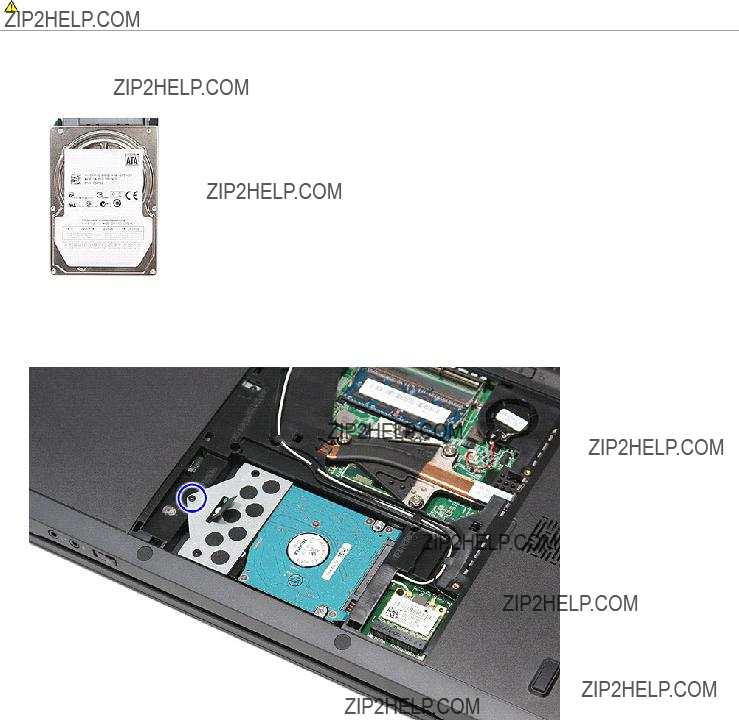
4.Remove the screw that secures the hard-drive assembly to the computer.
5. Slide the hard-drive assembly towards the center of the computer and lift it up and away from the computer.
6. Remove the screws that secure the hard-drive bracket to the hard drive.
7. Lift up the hard-drive bracket and remove it from the hard-drive assembly.
Replacing the Hard Drive
To replace the hard drive, perform the above steps in reverse order.
Back to Contents Page
14. Loosen the screws that secure the heat sink and fan assembly to the system board.
15. Lift the heat sink and fan assembly up and away from the system board.
Replacing the Heat Sink and Fan Assembly
To replace the heat sink and fan assembly, perform the above steps in reverse order.
Back to Contents Page
Back to Contents Page
IO Board
Dell??? Vostro??? 3700 Service Manual
WARNING: Before working inside your computer, read the safety information that shipped with your computer. For additional safety best practices information, see the Regulatory Compliance Homepage at www.dell.com/regulatory_compliance.
Removing the IO Board
1.Follow the procedures in Before Working Inside Your Computer.
2.Remove the battery.
3.Remove the base cover.
4.Remove the coin-cell battery.
5.Remove the hard drive.
6.Remove the optical drive.
7.Remove the wireless local area network (WLAN) card.
8.Remove the keyboard.
9.Remove the palm rest.
10.Remove the display assembly.
11.Remove the ExpressCard cage.
12.Remove the system board.
13.Remove the screw that secures the IO board to the computer.
14. Lift the IO board and turn it over.
Replacing the IO Board
To replace the IO board, perform the above steps in reverse order.
Back to Contents Page
Back to Contents Page
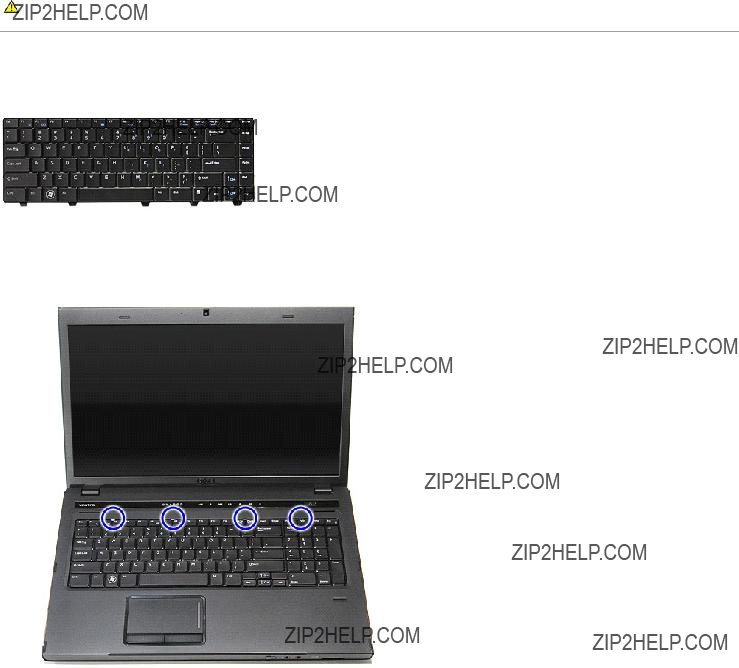
Keyboard
Dell??? Vostro??? 3700 Service Manual
WARNING: Before working inside your computer, read the safety information that shipped with your computer. For additional safety best practices information, see the Regulatory Compliance Homepage at www.dell.com/regulatory_compliance.
Removing the Keyboard
1.Follow the procedures in Before Working Inside Your Computer.
2.Remove the battery.
3.Flip the computer over with the right side facing up.
4.Using a small plastic scribe, press in on the release latches and pry the keyboard to release it.
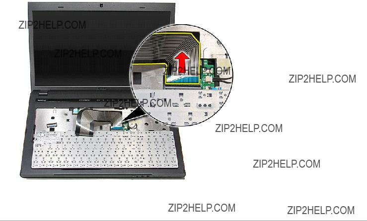
5. Lift the keyboard and turn it over.
6. Carefully open the clip to release the keyboard cable.
7. Disconnect the keyboard cable from its connector on the system board and remove the keyboard from the computer.
Replacing the Keyboard
To replace the keyboard, perform the above steps in reverse order.
Back to Contents Page
Back to Contents Page
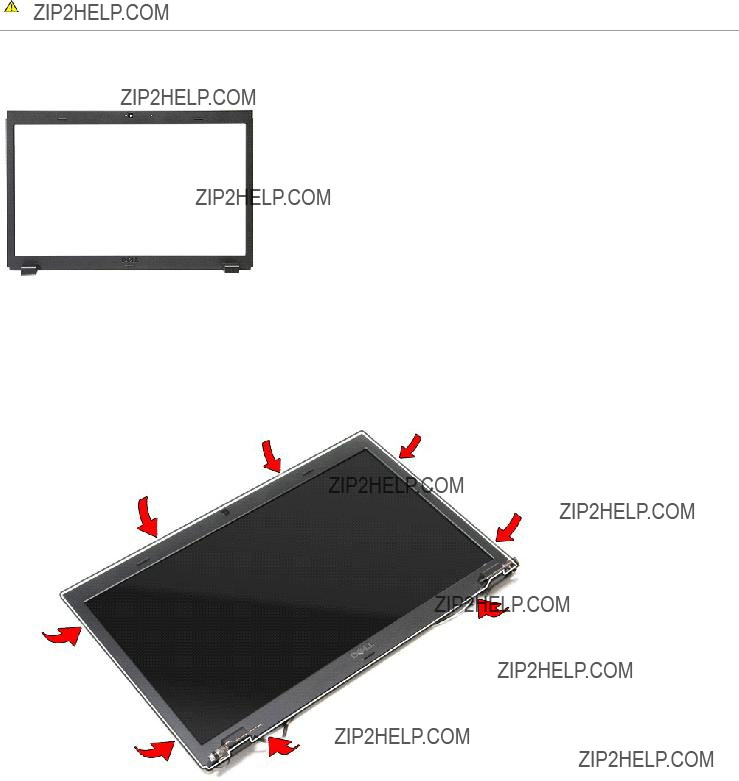
Display Bezel
Dell??? Vostro??? 3700 Service Manual
WARNING: Before working inside your computer, read the safety information that shipped with your computer. For additional safety best practices information, see the Regulatory Compliance Homepage at www.dell.com/regulatory_compliance.
Removing the Display Bezel
1.Follow the procedures in Before Working Inside Your Computer.
2.Remove the battery.
3.Remove the base cover.
4.Remove the hard drive.
5.Remove the optical drive.
6.Remove the wireless local area network (WLAN) card.
7.Remove the keyboard.
8.Remove the palm rest.
9.Remove the display assembly.
10.Using a plastic scribe, gently pry under the display bezel to release it from the display assembly.
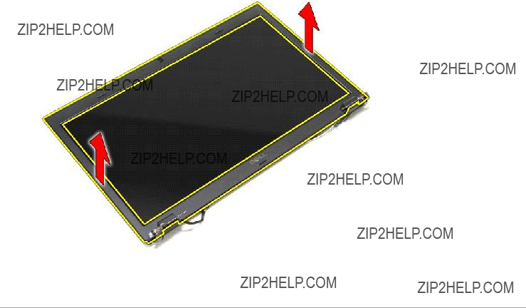
11. Lift the display bezel and remove it from the display assembly.
Replacing the Display Bezel
To replace the display bezel, perform the above steps in reverse order.
Back to Contents Page
Back to Contents Page
Display Hinges
Dell??? Vostro??? 3700 Service Manual
WARNING: Before working inside your computer, read the safety information that shipped with your computer. For additional safety best practices information, see the Regulatory Compliance Homepage at www.dell.com/regulatory_compliance.
Removing the Display Hinges
1.Follow the procedures in Before Working Inside Your Computer.
2.Remove the battery.
3.Remove the base cover.
4.Remove the hard drive.
5.Remove the optical drive.
6.Remove the wireless local area network (WLAN) card.
7.Remove the keyboard.
8.Remove the palm rest.
9.Remove the display assembly.
10.Remove the display panel.
11.Remove the screws that secure the display hinges to the display cover.
12. Remove the display hinges from the display cover.
Replacing the Display Hinges
To replace the display hinges, perform the above steps in reverse order.
Back to Contents Page
Back to Contents Page
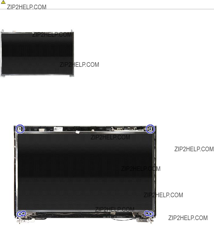
Display Panel
Dell??? Vostro??? 3700 Service Manual
WARNING: Before working inside your computer, read the safety information that shipped with your computer. For additional safety best practices information, see the Regulatory Compliance Homepage at www.dell.com/regulatory_compliance.
Removing the Display Panel
1.Follow the procedures in Before Working Inside Your Computer.
2.Remove the battery.
3.Remove the base cover
4.Remove the hard drive.
5.Remove the optical drive.
6.Remove the wireless wide area network (WLAN) card.
7.Remove the keyboard.
8.Remove the palm rest.
9.Remove the display assembly.
10.Remove the display bezel.
11.Remove the screws that secure the display panel to the display assembly.
12. Release the Display cable from the hinge to the left of the display panel.
13. Carefully lift the display panel from the display assembly.
14. Lift the display panel along with the hinges up and away from the display assembly.
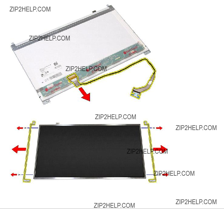
15. Remove the tape that secures the display cable to the dispaly panel.
16. Disconnect the display cable from its connector on the display panel.
17. Remove the screws that secure the display brackets to the display panel and remove the brackets from the display panel.
Replacing the Display Panel
To replace the display panel, perform the above steps in reverse order.
Back to Contents Page
Back to Contents Page
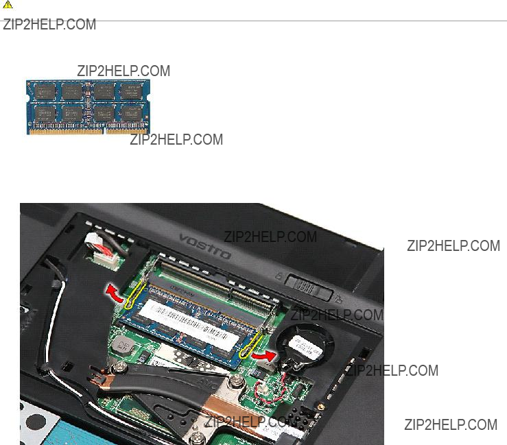
Memory
Dell??? Vostro??? 3700 Service Manual
WARNING: Before working inside your computer, read the safety information that shipped with your computer. For additional safety best practices information, see the Regulatory Compliance Homepage at www.dell.com/regulatory_compliance.
Removing the Memory Module(s)
1.Follow the procedures in Before Working Inside Your Computer.
2.Remove the battery.
3.Remove the base cover.
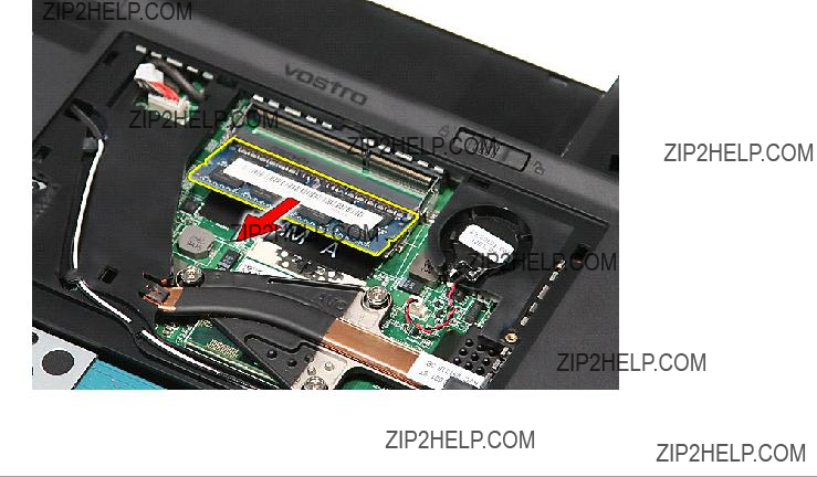
4.Push apart the memory retention clips to release the memory module.
5. Remove the memory module from its connector on the system board.
Replacing the Memory Module(s)
To replace the memory module(s), perform the above steps in reverse order.
Back to Contents Page
Back to Contents Page
Memory Card
Dell??? Vostro??? 3700 Service Manual
WARNING: Before working inside your computer, read the safety information that shipped with your computer. For additional safety best practices information, see the Regulatory Compliance Homepage at www.dell.com/regulatory_compliance.
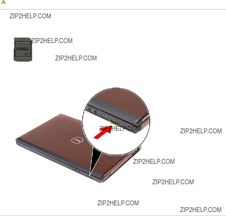
Removing the Memory Card
1.Follow the procedures in Before Working Inside Your Computer.
2.Press in on the memory card to release it from the computer.
3. Slide the memory card out and remove from the computer.
Replacing the Memory Card
To replace the memory card, perform the above steps in reverse order.
Back to Contents Page
Back to Contents Page
Optical Drive
Dell??? Vostro??? 3700 Service Manual
WARNING: Before working inside your computer, read the safety information that shipped with your computer. For additional safety best practices information, see the Regulatory Compliance Homepage at www.dell.com/regulatory_compliance.
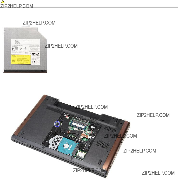
Removing the Optical Drive
1.Follow the procedures in Before Working Inside Your Computer.
2.Remove the battery.
3.Remove the base cover.
4.Remove the screw that secures the optical drive to the computer.
5. Using a screwdriver carefully, gently pry the optical drive and remove it from the computer.
Replacing the Optical Drive
To replace the optical drive, perform the above steps in reverse order.
Back to Contents Page
Back to Contents Page
Palm Rest
Dell??? Vostro??? 3700 Service Manual
WARNING: Before working inside your computer, read the safety information that shipped with your computer. For additional safety best practices information, see the Regulatory Compliance Homepage at www.dell.com/regulatory_compliance.
Removing the Palm Rest
1.Follow the procedures in Before Working Inside Your Computer.
2.Remove the battery.
3.Remove the base cover.
4.Remove the hard drive.
5.Remove the optical drive.
6.Remove the keyboard.
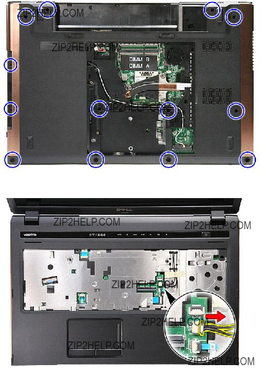
7.Remove the rubber feet at the bottom of the computer.
8. Remove the screws that secure the palm rest to the bottom of the computer.
9.Flip the computer over with the right side facing up.
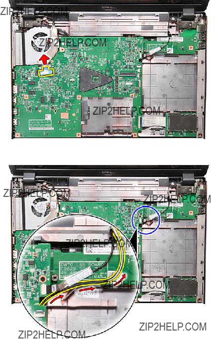
10.Disconnect the speaker cable from its connector on the system board.
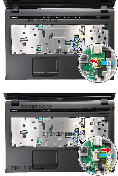
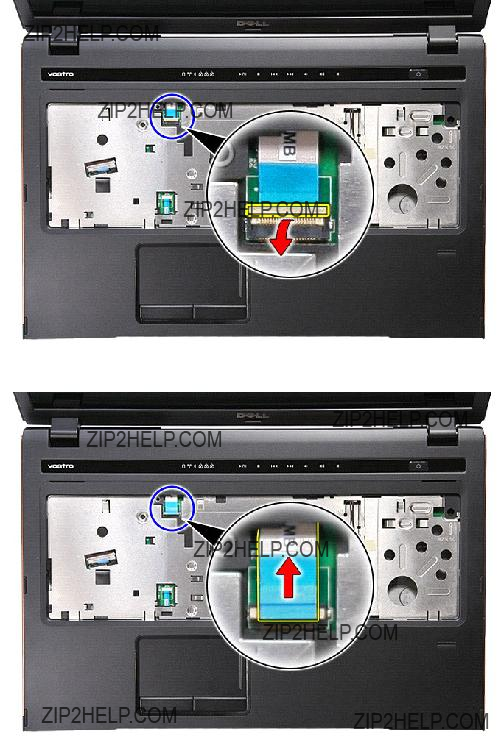
11. Open the clip that secures the fingerprint data cable to its connector on the system board.
12. Disconnect the fingerprint data cable from its connector on the system board.
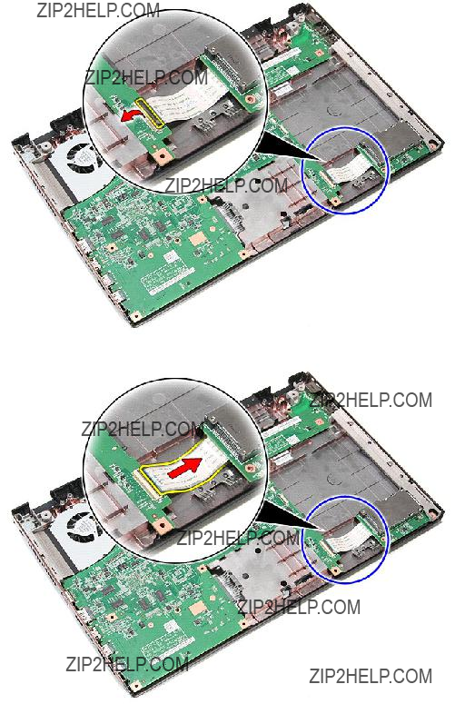
13. Open the clip that secures the audio cable to its connector on the system board.
14. Disconnect the audio cable from its connector on the system board.
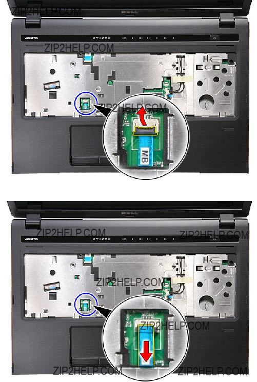
15. Open the clip that secures the touchpad data cable to its connector on the system board.
16. Disconnect the touchpad data cable from its connector on the system board.
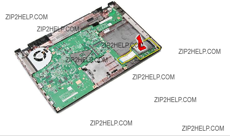
17. Open the clip that secures the media button data cable to its connector on the system board.
18. Disconnect the media button data cable from its connector on the system board.
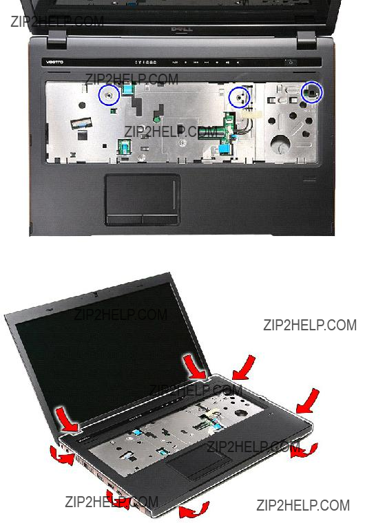
19. Remove the screws that secure the palm rest to the front of the computer.
20. Gently pry along the edges of the palm rest to release the palm rest.
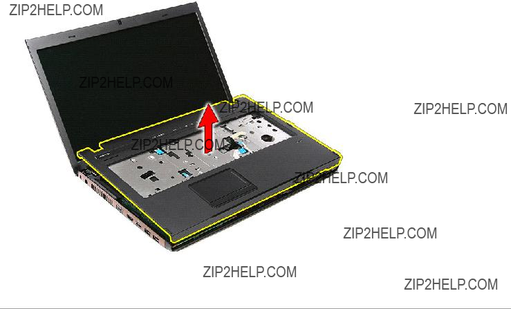
21. Lift the palm rest up and away from the computer.
Replacing the Palm Rest
To replace the palm rest, perform the above steps in reverse order.
Back to Contents Page
Back to Contents Page
Removing and Replacing Parts
Dell??? Vostro??? 3700 Service Manual
Back to Contents Page
Processor
Dell??? Vostro??? 3700 Service Manual
WARNING: Before working inside your computer, read the safety information that shipped with your computer. For additional safety best practices information, see the Regulatory Compliance Homepage at www.dell.com/regulatory_compliance.
Removing the Processor
1.Follow the procedures in Before Working Inside Your Computer.
2.Remove the battery.
3.Remove the base cover.
4.Remove the coin-cell battery.
5.Remove the hard drive.
6.Remove the optical drive.
7.Remove the wireless local area network (WLAN) card.
8.Remove the keyboard.
9.Remove the palm rest.
10.Remove the display assembly.
11.Remove the ExpressCard cage.
12.Remove the system board.
13.Remove the heat sink and fan assembly.
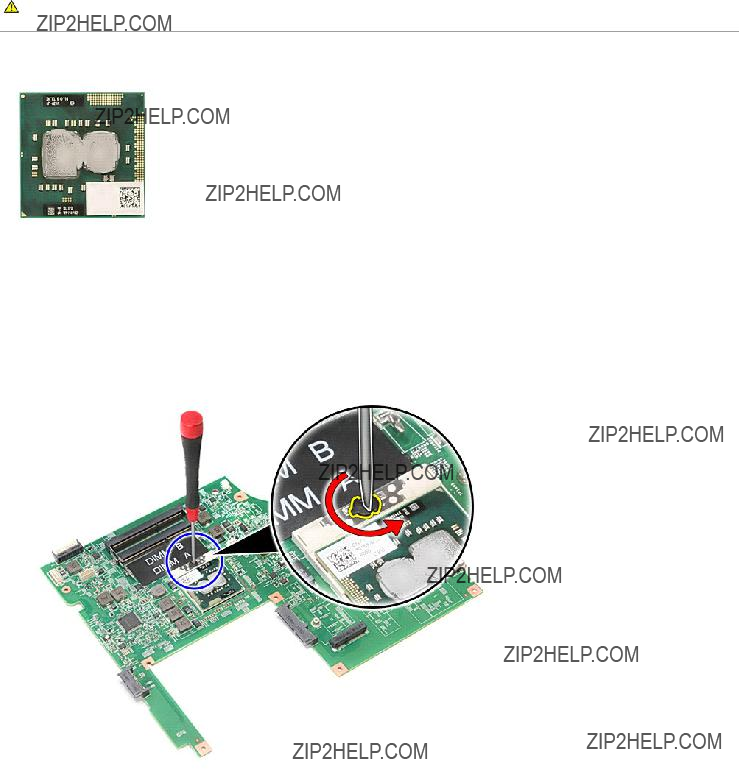
14.Using a flat-blade screwdriver, rotate the cam screw counterclockwise to release the processor from its socket on the system board.
15. Lift the processor up and away from the system board.
Replacing the Processor
CAUTION: While replacing the processor, ensure that the cam lock is in the fully open position before seating the processor module.
A processor module that is not properly seated can result in an intermittent connection or permanent damage to the microprocessor and ZIF socket.
To replace the processor, perform the above steps in reverse order.
Back to Contents Page
Back to Contents Page
Power-Button Board
Dell??? Vostro??? 3700 Service Manual
WARNING: Before working inside your computer, read the safety information that shipped with your computer. For additional safety best practices information, see the Regulatory Compliance Homepage at www.dell.com/regulatory_compliance.
Removing the Power-Button Board
1.Follow the procedures in Before Working Inside Your Computer.
2.Remove the battery.
3.Remove the base cover.
4.Remove the hard drive.
5.Remove the optical drive.
6.Remove the keyboard.
7.Remove the palm rest.
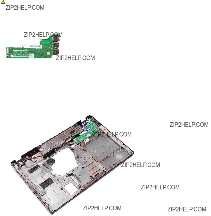
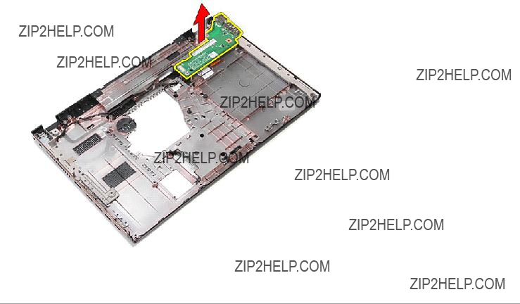
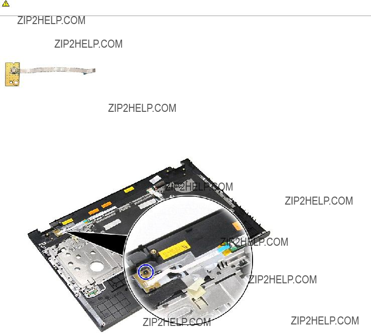
8.Remove the screw that secures the power-button board to the palm rest.
9. Open the clip that secures the power-button cable to its connector on the power-button board.
10. Disconnect the power-button cable from the power-button board.
11. Lift the power-button board up and away from the computer.
Replacing the Power-Button Board
To replace the power-button board, perform the above steps in reverse order.
Back to Contents Page
Back to Contents Page
Speakers
Dell??? Vostro??? 3700 Service Manual
WARNING: Before working inside your computer, read the safety information that shipped with your computer. For additional safety best practices information, see the Regulatory Compliance Homepage at www.dell.com/regulatory_compliance.
Removing the Speakers
1.Follow the procedures in Before Working Inside Your Computer.
2.Remove the battery.
3.Remove the base cover.
4.Remove the hard drive.
5.Remove the optical drive.
6.Remove the keyboard.
7.Remove the palm rest.
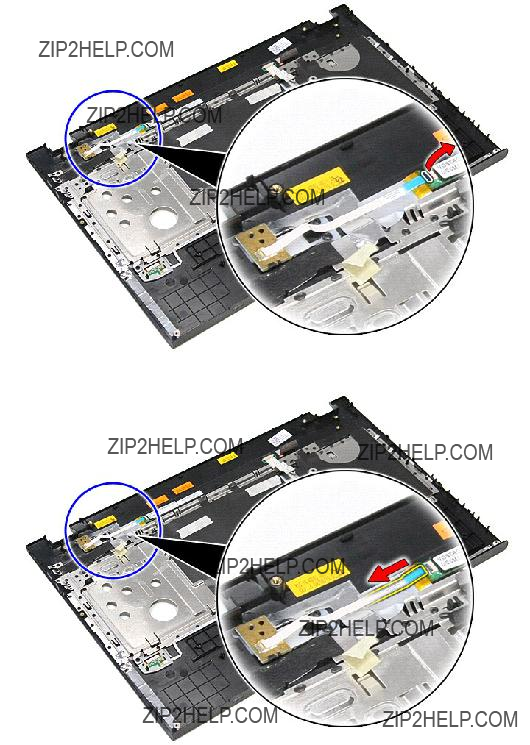
8.Remove the tape that secures the speaker cable to the front of the palm rest.
9. Remove the tapes that secure the speaker cables to the back of the palm rest.
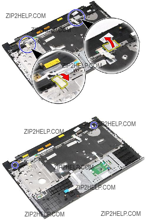
10. Remove the screws that secure the speakers to the palm rest.
11. Release the speakers from the palm rest.
12. Release the speaker cables from their routing guides on the palm rest and remove the speakers from the palm rest.
Replacing the Speakers
To replace the speakers, perform the above steps in reverse order.
Back to Contents Page
Back to Contents Page
Specifications
Dell??? Vostro??? 3700 Service Manual
NOTE: Offerings may vary by region. For more information regarding the configuration of your computer, click Start??? Help and Support and select the option to view information about your computer.
System Information
NOTE: Vibration is measured using a random-vibration spectrum that simulates user environment.
Maximum shock:
NOTE: Shock is measured with hard drive in head-parked position and a 2 ms half-sine pulse.
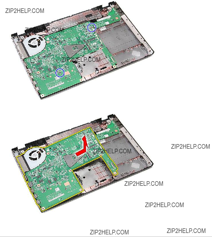
14. Remove the screws that secure the system board to the computer.
15. Gently lift the system board up and away from the computer.
Replacing the System Board
To replace the system board, perform the above steps in reverse order.
Back to Contents Page
Back to Contents Page
Wireless Local Area Network (WLAN) Card
Dell??? Vostro??? 3700 Service Manual
WARNING: Before working inside your computer, read the safety information that shipped with your computer. For additional safety best practices information, see the Regulatory Compliance Homepage at www.dell.com/regulatory_compliance.
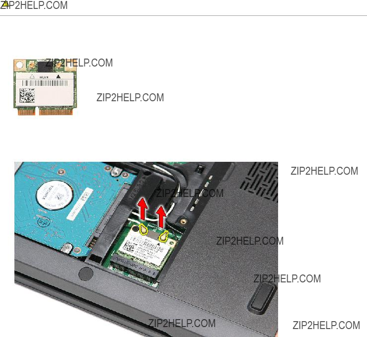
Removing the WLAN Card
1.Follow the procedures in Before Working Inside Your Computer.
2.Remove the battery.
3.Remove the base cover.
4.Disconnect the antenna cables from the WLAN card.
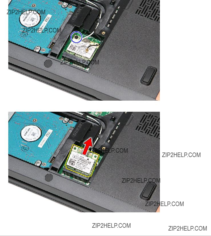
5. Remove the screw that secures the WLAN card to the system board.
6. Gently pull the WLAN card away from its connector on the system board and remove it from the computer.
Replacing the WLAN Card
To replace the WLAN Card, perform the above steps in reverse order.
Back to Contents Page
Working on Your Computer
Dell??? Vostro??? 3700 Service Manual
Before Working Inside Your Computer
Recommended Tools
Turning Off Your Computer
After Working Inside Your Computer
Before Working Inside Your Computer
Use the following safety guidelines to help protect your computer from potential damage and to help to ensure your personal safety. Unless otherwise noted, each procedure included in this document assumes that the following conditions exist:
???You have performed the steps in Working on Your Computer.
???You have read the safety information that shipped with your computer.
???A component can be replaced or--if purchased separately--installed by performing the removal procedure in reverse order.
WARNING: Before working inside your computer, read the safety information that shipped with your computer. For additional safety best practices information, see the Regulatory Compliance Homepage at www.dell.com/regulatory_compliance.
CAUTION: Many repairs may only be done by a certified service technician. You should only perform troubleshooting and simple repairs as authorized in your product documentation, or as directed by the online or telephone service and support team. Damage due to servicing that is not authorized by Dell is not covered by your warranty. Read and follow the safety instructions that came with the product.
CAUTION: To avoid electrostatic discharge, ground yourself by using a wrist grounding strap or by periodically touching an unpainted metal surface, such as a connector on the back of the computer.
CAUTION: Handle components and cards with care. Do not touch the components or contacts on a card. Hold a card by its edges or by its metal mounting bracket. Hold a component such as a processor by its edges, not by its pins.
CAUTION: When you disconnect a cable, pull on its connector or on its pull-tab, not on the cable itself. Some cables have connectors with locking tabs; if you are disconnecting this type of cable, press in on the locking tabs before you disconnect the cable. As you pull connectors apart, keep them evenly aligned to avoid bending any connector pins. Also, before you connect a cable, ensure that both connectors are correctly oriented and aligned.
NOTE: The color of your computer and certain components may appear differently than shown in this document.
To avoid damaging your computer, perform the following steps before you begin working inside the computer:
1.Ensure that your work surface is flat and clean to prevent the computer cover from being scratched.
2.Turn off your computer (see Turning Off Your Computer).
3.If the computer is connected to a docking device (docked) such as the optional Media Base or Battery Slice, undock it.
CAUTION: To disconnect a network cable, first unplug the cable from your computer and then unplug the cable from the network device.
4.Disconnect all network cables from the computer.
5.Disconnect your computer and all attached devices from their electrical outlets.
6.Close the display and turn the computer upside-down on a flat work surface.
CAUTION: To avoid damaging the system board, you must remove the main battery before you service the computer.
7.Remove the main battery (see Battery).
8.Turn the computer top-side up.
9.Open the display.
10.Press the power button to ground the system board.
CAUTION: To guard against electrical shock, always unplug your computer from the electrical outlet before opening the display.
CAUTION: Before touching anything inside your computer, ground yourself by touching an unpainted metal surface, such as the metal at the back of the computer. While you work, periodically touch an unpainted metal surface to dissipate static electricity, which could harm internal components.
11.Remove any installed ExpressCards or Smart Cards from the appropriate slots.
12.Remove the hard drive (see Hard Drive).
Recommended Tools
The procedures in this document may require the following tools:
???Small flat-blade screwdriver
???#0 Phillips screwdriver
???#1 Phillips screwdriver
???Small plastic scribe
???Flash BIOS update program CD
Turning Off Your Computer
CAUTION: To avoid losing data, save and close all open files and exit all open programs before you turn off your computer.
1. Shut down the operating system:
???In Windows Vista??:
Click Start  , then click the arrow in the lower-right corner of the Start menu as shown below, and then click Shut Down.
???In Windows?? XP:
Click Start ??? Turn Off Computer ??? Turn Off.
The computer turns off after the operating system shutdown process is complete.
2.Ensure that the computer and all attached devices are turned off. If your computer and attached devices did not automatically turn off when you shut down your operating system, press and hold the power button for about 6 seconds to turn them off.
After Working Inside Your Computer
After you complete any replacement procedure, ensure you connect any external devices, cards, and cables before turning on your computer.
CAUTION: To avoid damage to the computer, use only the battery designed for this particular Dell computer. Do not use batteries designed for other Dell computers.
1. Connect any external devices, such as a port replicator, battery slice, or media base, and replace any cards, such as an ExpressCard.
CAUTION: To connect a network cable, first plug the cable into the network device and then plug it into the computer.
2.Connect any telephone or network cables to your computer.
3.Replace the battery.
4.Connect your computer and all attached devices to their electrical outlets.
5.Turn on your computer.
Back to Contents Page