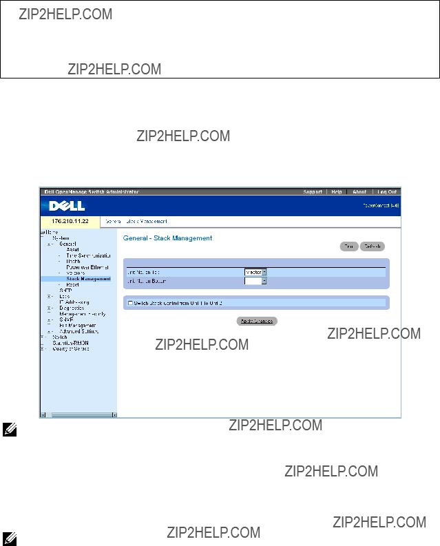
Once the user selects a different Unit ID, it is not erased, and remains valid, even if the unit is reset.
Unit ID 1 and Unit ID 2 are reserved for Master enabled units. Unit IDs 3 to 6 can be defined for stack members.
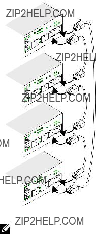
When the Master unit boots or when inserting or removing a stack member, the Master unit initiates a stacking discovering process.
NOTE: If two members are discovered with the same Unit ID the stack continues to function, however only the unit with the older join time joins the stack. A message is sent to the user, notifying that a unit failed to join the stack.
Removing and Replacing Stacking Members
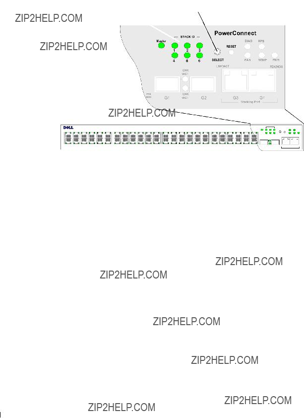
Unit 1 and Unit 2 are Master enabled units. Unit 1 and Unit 2 are either designated as Master Unit or Backup Master Unit. The stack Master assignment is performed during the configuration process. One Master enabled stack member is elected as Master, and the other Master enabled stack member is elected as Backup Master, according to the following decision process:
???If only one Stack Master enabled unit is present, it is elected as the Master.
???If two Master enabled stacking members are present, and one has been manually configured as the Stack Master, the manually configured member is elected as Stack Master.
???If two Master enabled units are present and neither has been manually configured as the Master, the one with the longer up-time is elected as the Stack Master.
???If two Master enabled units are present and both have been manually configured as the Master, the one with the longer up-time is elected as the Stack Master.
???If the two Master enabled stacking members are the same age, Unit 1 is elected as the Stack Master.
NOTE: Two stacking member are considered the same age if they were inserted within a ten minute interval.
For example, Unit 2 is inserted in the first minute of a ten-minute cycle, and Unit 1 is inserted in fifth minute of the same cycle, the units are considered to be the same age. If there are two Master enabled stack members that are the same age, then Unit 1 is elected master.
The Stack Master and the Backup Master maintain a Warm Standby. The Warm Standby ensures that the Backup Master takes over for the Stack Master if a failover occurs. This guarantees that the stack continues to operate normally.
During the Warm Standby, the Master and the Backup Master are synchronized with the static configuration only. When the Stacking Master is configured, the Stack Master must synchronize the Stacking Backup Master. The Dynamic configuration is not saved, for example, dynamically learned MAC addresses are not saved.
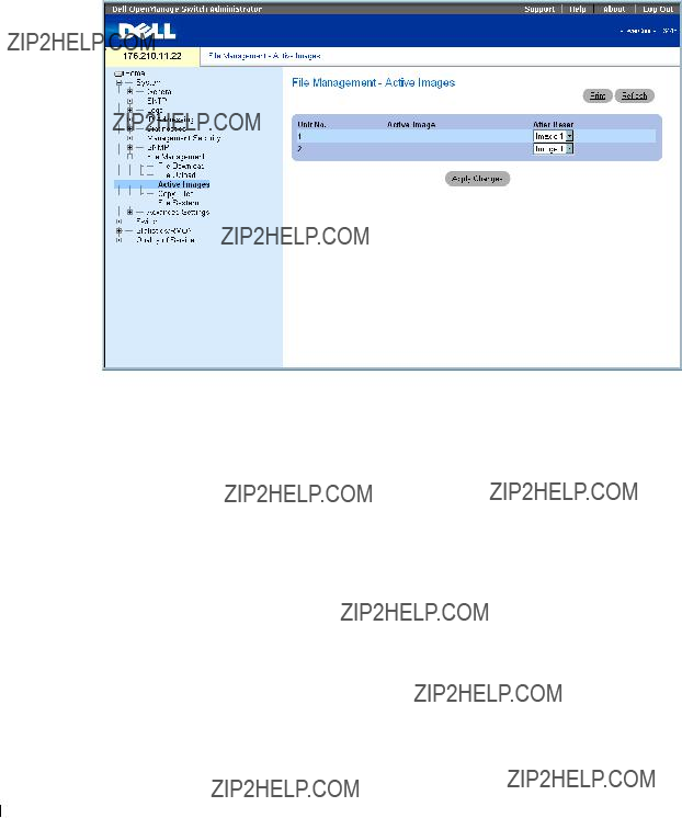
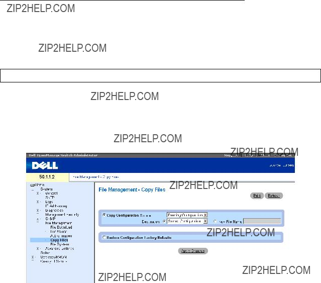
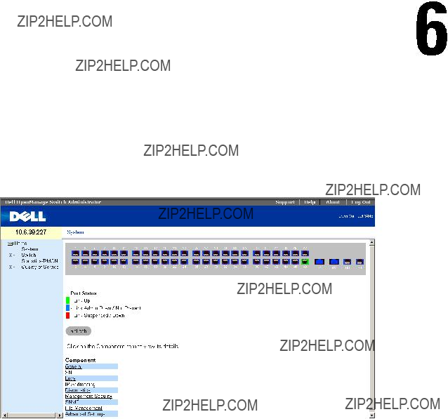
Each port in the stack has a specific Unit ID, port type, and port number, which are part of both the configuration commands and the configuration files. Configuration files are managed only from the device Stack Master, including:

 CAUTION: A CAUTION indicates a potential for property damage, personal injury, or death.


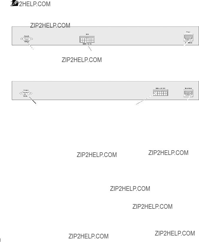


 Back Panel


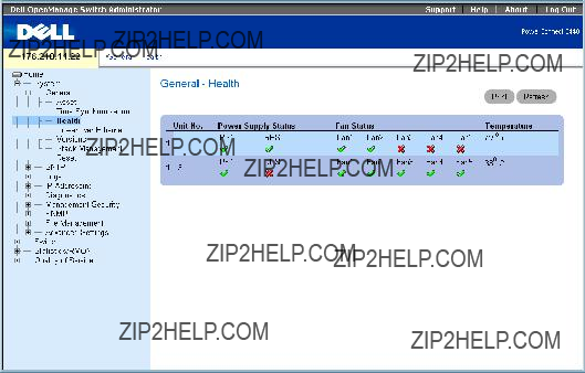
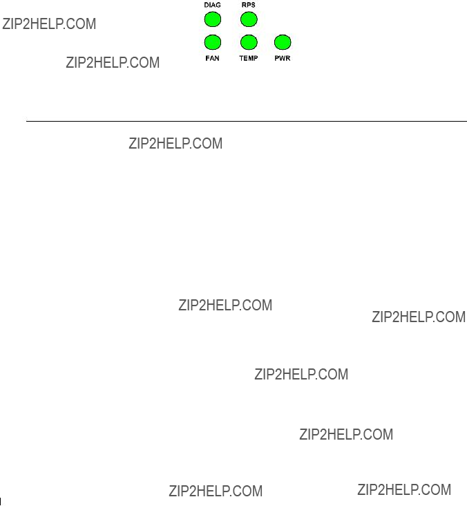
 ??? The power supply is operating normally.
 ??? The power supply is not operating normally.
 ??? The fan is operating normally.
 ??? The fan is not operating normally.


 .
.