Dell 1815dn
Service Manual
27 Mar 2006
Dell 1815dn
Service Manual
27 Mar 2006
Information in this document is subject to change without notice. 2010 Dell Inc. All rights reserved.
Reproduction in any manner whatsoever without the written permission of Dell Inc.is strictly forbidden. Trademarks used in this text: Dell and the DELL logo are trademarks of Dell Inc.
Other trademarks and trade names may be used in this document to refer to the entities claiming the marks and names of their products. Dell Inc. disclaims any proprietary interest in trademarks and trade names other than its own.

Precautions
11. Precautions
In order to prevent accidents and to prevent damage to the equipment please read the precautions listed below carefully before servicing the printer and follow them closely .
1.1 Safety Warning
(1)Only to be serviced by appropriately qualified service engineers.
High voltages and lasers inside this product are dangerous. This printer should only be serviced by a suitably trained and qualified service engineer.
(2)Use only Dell replacement parts
There are no user serviceable parts inside the printer . Do not make any unauthorized changes or
additions to the printer, these could cause the printer to malfunction and create electric shock or fire
(3)Laser Safety Statement
The Printer is certified in the U.S. to conform to the requirements of DHHS 21 CFR, chapter 1 Subchapter J for Class 1(1) laser products, and elsewhere, it is certified as a Class I laser product
Warning >> Never operate or service the printer with the protective cover removed from Laser/Scanner assembly. The reflected beam, although invisible, can damage your eyes. When using this product, these basic safety
CAUTION - INVISIBLE LASER RADIATION
WHEN THIS COVER OPEN.
DO NOT OPEN THIS COVER.
VORSICHT - UNSICHTBARE LASERSTRAHLUNG,
WENN ABDECKUNG GE FFNET.
NICHT DEM STRAHL AUSSETZEN.
ATTENTION - RAYONNEMENT LASER INVISIBLE EN CAS
D OUVERTURE. EXPOSITION DANGEREUSE
AU FAISCEAU.
ATTENZIONE - RADIAZIONE LASER INVISIBILE IN CASO DI
APERTURA. EVITARE L ESPOSIZIONE AL
FASCIO.
PRECAUCION - RADIACION LASER IVISIBLE CUANDO SE ABRE.
EVITAR EXPONERSE AL RAYO.
ADVARSEL. - USYNLIG LASERSTR LNING VED BNING, N R
SIKKERHEDSBRYDERE ER UDE AF FUNKTION.
UNDG UDSAETTELSE FOR STR LNING.
ADVARSEL. - USYNLIG LASERSTR LNING N R DEKSEL
PNES. STIRR IKKE INN I STR LEN.
UNNG EKSPONERING FOR STR LEN.
VARNING - OSYNLIG LASERSTR LNING N R DENNA DEL
R PPNAD OCH SP RREN R URKOPPLAD.
BETRAKTA EJ STR LEN. STR LEN R FARLIG.
VARO! - AVATTAESSA JA SUOJALUKITUS OHITETTAESSA
OLET ALTTIINA N KYM TT M LLE LASER-
S TEILYLLE L KATSO S TEESEEN.

Precautions
1.2 Caution for safety
1.2.1 Toxic material
This product contains toxic materials that could cause illness if ingested.
(1)If the LCD control panel is damaged it is possible for the liquid inside to leak. This liquid is toxic. Contact with the sk in should be avoided, wash any splashes from eyes or skin immediately and contact your doctor . If the liquid gets into the mouth or is swallowed see a doctor immediately.
(2)Please keep toner cartridges away from children. The toner powder contained in the toner cartridge may be harmful and if swallowed you should contact a doctor.
1.2.2 Electric Shock and Fire Safety Precautions
Failure to follow the following instructions could cause electric shock or potentially cause a fire.
(1)Use only the correct voltage, failure to do so could damage the printer and potentially cause a fire or electric shock.
(2)Use only the power cable supplied with the printer . Use of an incorrectly specified cable could cause the cable to overheat and potentially cause a fire.
(3)Do not overload the power socket, this could lead to overheating of the cables inside the wall and could lead to a fire.
(4)Do not allow water or other liquids to spill into the printer , this can cause electric shock. Do not allow paper clips, pins or other foreign objects to fall into the printer these could cause a short circuit leading to an electric shock or fire hazard..
(5)Never touch the plugs on either end of the power cable with wet hands, this can cause electric shock. When servicing the printer remove the power plug from the wall socket.
(6)Use caution when inserting or removing the power connector . The power connector must be inserted com - pletely otherwise a poor contact could cause overheating possibly leading to a fire. When removing the power connector grip it firmly and pull.
(7)Take care of the power cable. Do not allow it to become twisted, bent sharply round corners or other wise damaged. Do not place objects on top of the power cable. If the power cable is damaged it could overheat and cause a fire or exposed cables could cause an electric shock. Replace a damaged power cable immediately , do not reuse or repair the damaged cable. Some chemicals can attack the coating on the power cable, weakening the cover or exposing cables causing fire and shock risks.
(8)Ensure that the power sockets and plugs are not cracked or broken in any way . Any such defects should be repaired immediately. Take care not to cut or damage the power cable or plugs when moving the machine.
(9)Use caution during thunder or lightening storms. Dell recommends that this machine be disconnected from the power source when such weather conditions are expected. Do not touch the machine or the power cord if it is still connected to the wall socket in these weather conditions.
(10)Avoid damp or dusty areas, install the printer in a clean well ventilated location. Do not position the machine near a humidifier. Damp and dust build up inside the machine can lead to overheating and cause a fire.
(11)Do not position the printer in direct sunlight. This will cause the temperature inside the printer to rise possibly leading to the printer failing to work properly and in extreme conditions could lead to a fire.
(12)Do not insert any metal objects into the machine through the ventilator fan or other part of the casing, it could make contact with a high voltage conductor inside the machine and cause an electric shock.

Precautions
1.2.3 Handling Precautions
The following instructions are for your own personal safety, to avoid injury and so as not to damage the printer
(1)Ensure the printer is installed on a level surface, capable of supporting its weight. Failure to do so could cause the printer to tip or fall.
(2)The printer contains many rollers, gears and fans. Take great care to ensure that you do not catch your fingers, hair or clothing in any of these rotating devices.
(3)Do not place any small metal objects, containers of water , chemicals or other liquids close to the printer which if spilled could get into the machine and cause damage or a shock or fire hazard.
(4)Do not install the machine in areas with high dust or moisture levels, beside on open window or close to a humidifier or heater. Damage could be caused to the printer in such areas.
(5)Do not place candles, burning cigarettes, etc on the printer , These could cause a fire.
1.2.4 Assembly / Disassembly Precautions
Replace parts carefully, always use Dell parts. Take care to note the exact location of parts and also
cable routing before dismantling any part of the machine. Ensure all parts and cables are replaced correctly . Please carry out the following procedures before dismantling the printer or replacing any parts.
(1)Check the contents of the machine memory and make a note of any user settings. These will be erased if the mainboard or network card is replaced.
(2)Ensure that power is disconnected before servicing or replacing any electrical parts.
(3)Disconnect printer interface cables and power cables.
(4)Only use approved spare parts. Ensure that part number , product name, any voltage, current or temperature rating are correct.
(5)When removing or
(6)Take care not to drop any small parts into the machine.
(7)Handling of the OPC Drum
-The OPC Drum can be irreparably damaged if it exposed to light.
Take care not to expose the OPC Drum either to direct sunlight or to fluorescent or incandescent room lighting. Exposure for as little as 5 mins can damage the surface??? s photoconductive properties and will result in print quality degradation. Take extra care when servicing the printer. Remove the OPC Drum and store it in a black bag or other lightproof container. Take care when working with the covers(especially the top cover) open as light is admitted to the OPC area and can damage the OPC Drum.
-Take care not to scratch the green surface of OPC Drum Unit.
If the green surface of the Drum Cartridge is scratched or touched the print quality will be compromised.

Precautions
1.2.5 Disregarding this warning may cause bodily injury
(1)Be careful with the high temperature part.
The fuser unit works at a high temperature. Use caution when working on the printer . Wait for the fuser to cool down before disassembly.
(2)Do not put finger or hair into the rotating parts.
When operating a printer, do not put hand or hair into the rotating parts (Paper feeding entrance, motor , fan, etc.). If do, you can get harm.
(3)When you move the printer.
This printer weighs 17.5kg including toner cartridge and cassette. Use safe lifting and handling techniques. Use the lifting handles located on each side of the machine. Back injury could be caused if you do not lift carefully .
(4)Ensure the printer is installed safely.
The printer weighs 17.5Kg, ensure the printer is installed on a level surface, capable of supporting its weight. Failure to do so could cause the printer to tip or fall possibly causing personal injury or damaging the printer .
(5)Do not install the printer on a sloping or unstable surface. After installation, double check that the printer is stable.

Precautions
1.3 ESD Precautions
Certain semiconductor devices can be easily damaged by static electricity . Such components are commonly called ???Electrostatically Sensitive (ES) Devices???, or ESDs. Examples of typical ESDs are: integrated circuits, some field effect transistors, and semiconductor ???chip??? components.
The techniques outlined below should be followed to help reduce the incidence of component damage caused by static electricity.
Caution >>Be sure no power is applied to the chassis or circuit, and observe all other safety precautions.
1. Immediately before handling a semiconductor component or
2. After removing an electrical assembly equipped with ESDs, place the assembly on a conductive surface, such as aluminum or copper foil, or conductive foam, to prevent electrostatic charge buildup in the vicinity of the assem - bly.
3.Use only a grounded tip soldering iron to solder or desolder ESDs.
4.Use only an
5.Do not use
6.Do not remove a replacement ESD from its protective packaging until immediately before installing it. Most replacement ESDs are packaged with all leads shorted together by conductive foam, aluminum foil, or a compa - rable conductive material.
7.Immediately before removing the protective shorting material from the leads of a replacement ESD, touch the pro- tective material to the chassis or circuit assembly into which the device will be installed.
8.Maintain continuous electrical contact between the ESD and the assembly into which it will be installed, until com- pletely plugged or soldered into the circuit.
9.Minimize bodily motions when handling unpackaged replacement ESDs. Normal motions, such as the brushing together of clothing fabric and lifting one??? s foot from a carpeted floor , can generate static electricity suf ficient to damage an ESD.
1.4 Super Capacitor or Lithium Battery Precautions
1.Exercise caution when replacing a super capacitor or Lithium battery . There could be a danger of explosion and subsequent operator injury and/or equipment damage if incorrectly installed.
2.Be sure to replace the battery with the same or equivalent type recommended by the manufacturer.
3.Super capacitor or Lithium batteries contain toxic substances and should not be opened, crushed, or burned for disposal.
4.Dispose of used batteries according to the manufacture??? s instructions.

Reference Information
22. Reference Information
This chapter contains the tools list, list of abbreviations used in this manual, and a guide to the location space required when installing the printer. A definition of tests pages and Wireless Network information definition is also included.
2.1 Tool for Troubleshooting
The following tools are recommended safe and easy troubleshooting as described in this service manual.
???DVM(Digital Volt Meter)
Standard : Indicates more than 3 digits.
???Driver
Standard :
???Tweezers
Standard : For general home use, small type.
???Cotton Swab
Standard : For general home use, for medical service.
???Cleaning Equipments
Standard : An IPA(Isopropyl Alcohol)dry wipe tissue or a gentle neutral detergent and
??? Vacuum Cleaner
??? Spring Hook
Standard : For general use
??? Software (Driver) installation CD ROM

Reference Information
2.2 Acronyms and Abbreviations
The table in the below explains abbreviations used in this service manual.
The contents of this service manual are declared with abbreviations in many parts. Please refer to the table.
Reference Information
2.3 The Sample Pattern for the Test
The sample pattern shown in below is the standard pattern used in the factory .
The life of the toner cartridge and the printing speed are measured using the pattern shown below . (The image is 70% of the actual A4 size).
2.3.1 A4 ISO 19752 Standard Pattern
This test page is reproduced at 70% of the normal A4 size
Product Specifications
33. Product Specifications
Specfications are correct at the time of printing. Product specifications are subject to change without notice. See below for product specifications.
3.1 Product Overview
 Concept: MFP of high speed
 Target User : Small & Medium Business
 Customer Benefits (Sales Points)
-Fast Printing Speed
(25ppm in A4 / 27ppm in Letter)
-Multifunction Network Solution
-Duplex Capability
-Direct USB Connectivity 2nd Version (PDF Direct Printing)
-Small Foot Print
 Key Features
-25 ppm Print speed/14 cpm Copy Speed
-1200 dpi Print Resolution (Addressable)
-PCL6,
-64MB System Memory/32MB DIMM(5530FN)
-50 ADF
-250 sh Paper Input / 150 sh Paper Output
-33.6 Kbps Fax Modem (5530FN only)
-Duplex Print (5530FN only)

Product Specifications
3.2 Product General Specifications

Product Specifications

Product Specifications

Product Specifications

Product Specifications

Product Specifications

Product Specifications

System Outline
44. System Outline
This document is the product specification for Dell 1815dn. Dell 1815dn is a
Dell 1815dn is developed to meet standard approvals of FCC Part 15 Class B, FCC Part 68, IC 60950, and cUL for the US and Canada. Other markets covered are Europe, Latin America and Emerging Markets. Agency Certifications will be attained to enable launch in all target markets
4.1 System Configurations
Dell 1815dn is made up of the Main Control part, Operation Panel part, Scanner part, Line interface part and Power part. Each Part is a separate Module which focuses on common and standard design of
different kind of products. Main control part adopting Fax & LBP Printer exclusive Controller is composed of 1 CPU and 1 Board. Scanner part is composed of ADF and Platen and is connected with Main by Harness. Line Interface part is designed to apply TBR21 standard (Domestic, Europe, etc.)
4.1.1 CPU Part
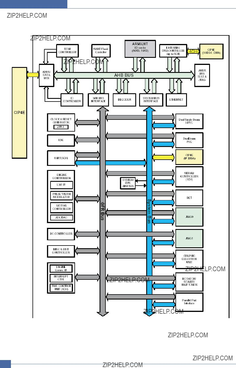
1) CPU : ARM920T , which is exclusive controller to execute Printer & F AX Function and to execute opera- tion block by flash memory within system program, and to control whole system.
 Main function block
 Completely Integrated System for Embedded Applications
 PVC
PVC
- Dual / Single Beam, - LVDS Pad (VDO, HSYNC), - Support A3 1200dpi,
 HPVC
HPVC
- Dual / Single Beam, - LVDS Pad (VDO, HSYNC), - Support A4 600dpi,
 DMA
DMA
-6 Channels (if not use CIP4e, 4ch is available for external DMA.
if CIP4E used (a4 DMA channel use), 2ch available for external DMA)
 Operation Frequency : CPU Core
 Operation Voltage : Core Voltage
2) Flash Memory : Record System Program, and download System Program by PC INTERF ACE. FAX for Journal List, and Memory for One Touch Dial, Speed Dial List.
-size : 16M Byte (NOR Flash)
-Access Time: 90ns (Max)
-Page Access Time: 25ns (Max)

System Outline
3) SDRAM : is used as Swath Buffer in Printing, Scan Buffer in Scanning, ECM Buffer in FAX receiving, and System Working Memory Area
- size : 64Mbyte(Basic) , 96Mbyte(Duplex)
4MB : System Working Memory Area and Scan Buffer
4MB : FAX Memory Receive Area
16MB : Printing System Working Memory Area
-Max Frequency : 166MHz
-store Fax Receive Memory Data by using Battery
4.1.2 FAX Section
Modem Part
BLOCK DIAGRAM
Implemented by based on Conexant DAA (Data Access Arrangement) Solution, and is roughly composed of two kinds Chip Solution
-CX86710 (SFX336): Existing Modem Chip which adds SSD (System Side Device) for interfacing between LSD and DIB of FM336Plus Core
-CX20493 (LSD) : LIU (Line Interface Unit) Chip which is controlled by SSD and satisfies each PSTN Requirements by modulating internal Configuration with connecting Tel Line.
System Outline
Modem (SFX336) specification.

 V.17, V.34, V.29, V.27 ter, and V.21 Channel 2
 Short train option in V.17 and V.27 ter
 PSTN session starting
 V.8 and V.8bis signaling
 HDLC support at all speeds
 Flag generation,
 Flag detection,
 FSK flag pattern detection during
 Tone modes and features
 Programmable single or dual tone generation
 DTMF receiver
 Tone detection with three programmable tone detectors
 Receive dynamic range:
 0 dBm to
  43 dBm for V.17, V.29, V.27 ter and V.21 Channel 2
 9dBm to
 Digital speaker output to monitor received signal

 V.21 Channel 1Flag detect
 V.21 Channel 1Flag detect
 +3.3V only operation
 Typical power consumption
  Normal mode: 264 mW

System Outline
Signal Transition of DAA Solution
Line Interface Signal of Tel Line and LSD is Analog Signal.
2)there is A/D, D/A Converter in LSD, so Analog Signal from Tel Line is converted in Digital through A/D Converter in DAA and transfer to SSD by DIB Capacitor
Digital Signal from SSD is converted to Analog by D/A Converter in DAA and transfer to Tel Line
Transformer transfer Clock from SSD to LSD and Clock Frequency is 4.032MHz.
LSD full wave rectifies Clock to use as inner Power supply and also use as Main Clock for DIB Protocol Sync between LSD and SSD. Transformer transfer Clock by separating Primary and Secondary, and amplifies Clock Level to LSD by Coil Turns Ratio 1:1.16.
 Clock
Clock
-Clock is supplied by transformer from SSD to LSD, and there is PWROUT to adjust output impedance of Clock
Out Driver is inside SSD and CLKSHIGH Resistor to adjust duty of HLPWR Resistor and Clock. Clock from SSD to LSD has Dif ferential structure of 180 phase difference for Noise Robustness
DIB Data transfer Data from SSD to LSD by Transformer, and also transfer specific data from LSD to SSD.
After transferring data from SSD, RSP is transferred and LSD recognizes RSP and change LSD to output Driver transfer Data to SSD.
DIB Data form SSD to LSD by Transformer has Differential structure of 180 phase difference between DIBP and DIBN for Noise Robustness

System Outline
4.1.3 Line Interface Part
This is Connection Part between system and PSTN(Public Switched Telephone Network), and primary circuit is usually located. Main functions are Line Interface, Telephone Connection and Line Condition Monitoring.
1 Telephone Line Connection
 Modular Plug :
 LIU PBA Modular Type : 623
 Line Code Length : 2500
  50mm
50mm
 Line Code Color : Black
ON HOOK state Characteristic 1) DC Resistance
 DP Dial Mode (Direct Current 30mA) : 50 ~ 300ohm
  DTMF Dial Mode (Direct Current 20mA) : 50 ~ 540ohm
2) Ring Sensitivity
 Ring detection Voltage : 40Vrms
  150Vrms (condition :Current=25mA,Frequency=15Hz) product Margin : 30Vrms
  150Vrms
 Ring detection Frequency : 15.3Hz
  68Hz (condition : Voltage=45Vrms,Current=25mA ) product Margin : 15Hz
  70Hz
70Hz
 Ring detection Current : 20mA
  100mA (condition : Voltage=40Vrms,Frequency=20Hz) product Margin : over 15mA
3) False Ring Sound
 Ring Frequency : 750 Hz + 1020 Hz
 Ring interrupt Cycle : On/Off depending on input Ring Signal Cycle.

System Outline
4.1.4 Scan Part
Pictorial signal input part: output signal of CCD passes through Bypass Cap change to ADC at HT82V26, and defined signal between HT82V26 and CHORUSm processes the Image signal. When AFE accept each pixel, CDS(Correlated Double Sampling ) technique which samples
2) Pictorial image processing part: read CCD Pixel data in terms of 600dpi Line and process Error Diffusion Algorithm on Text mode and Photo mode, and then store Data at Scan Buf fer on PC Scan mode without algo - rithm.
On every mode Shading Correction and Gamma Correction are executed ahead, then processing is executed later.
* Scan Image Control Specification
 Minimum Scan Line Time: 0.75ms
 main function
-Internal 12bit ADC
-White Shading Correction
-Gamma Correction
-CCD Interface
-256 Gray Scale
3)CCD Operating Part : CCD Image sensor use +5V and Inverter uses +24V
- CCD Maximum Operating Frequency : 10MHz
- White Data output Voltage : 0.7V  0.5V (Mono Copy, 0.75ms/line)
- Maximum Inverter Current : 600 mA Max.( +24V)
4.1.5 OPE Pannel Section
(1) Configuration
Operations Panel uses Main Control and separated OPE Chip Micom and work as inner program,
systemic operation is serial system which exchange Date with SIO Port of Main Control. OPE Panel is approxi - mately composed of Micom part, Matrix part and LCD.
(2) Micom controller
Micom has ROM, RAM, I/O Port

System Outline
4.1.6 Printer Section
Printer is consisted of the Engine parts and F/W , and engine parts is consisted of the mechanical parts comprising Frame, Feeding, Developing, Driving, Transferring, Fusing, Cabinet and H/W comprising the main control board, power board, operation panel, PC Interface.
The main controller is consisted of ASIC (CHORUSm) parts, Memory parts, Engine Interface parts and it functions as Bus Control, I/O Handling, drivers & PC Interface by CPU.
The Engine Board and the Controller Board are in one united board, and it is consisted of CPU part and print part in functional aspect. The CPU is functioned as the bus control, I/O handling, drivers, and PC interface. The main board sends the Current Image, Video data to the LSU and manages the conduct of Electro photography for print - ing. It is consisted of the circuits of the motor (paper feed, pass) driving, clutch driving,
The signals from the paper feed jam sensor and paper empty sensor are directly inputted to the main board.
Service Manual

System Outline
ASIC

System Outline
System Outline

System Outline
4.1.7 Copier Section
Service Manual

System Outline
4.1.8 Telephone Section
4.1.9 SMPS & HVPS SECTION
The SMPS supplies DC Power to the System.
It takes 110V/220V and outputs the +5V, +24V to supply the power to the main board and ADF board. The HVPS board creates the high voltage of THV/MHV/Supply/Dev and supplies it to the developer part for making best condition to dis - play the image. The HVPS part takes the 24V and outputs the high voltage for THV/MHV/BIAS, and the outputted high voltage is supplied to the toner, OPC cartridge, and transfer roller.
HVPS (High Voltage Power Supply)
 Transfer High Voltage (THV+)
 Input Voltage: 24 V DC
  15%
15%
 Output Voltage: MAX +5.0KV Duty Variable,)
  15% ()
 Output Voltage Trigger: 6.5
 Line Regulation : under
 3% (fluctuation input 21.6V ~ 27.6V)
 Output Voltage Rising Time 50ms Max
 Output Voltage Falling Time : 100 ms Max
 Fluctuating transfer voltage with environmental various : +650 V(Duty 10%) ~ 5 KV (Duty 90%)
Environment Recognition Control Method : The
Output Voltage Control Method : Transfer Output Voltage is outputted and controlled by changing Duty of THVPWM
Signal. 10% Duty : +650V, 90% Duty : +5KV
System Outline
 Charge Voltage (MHV)
 Input Voltage : 24 V DC
  15%
15%
 Output Voltage :
  3%
3%
 Output Voltage Rising Time : 50 ms Max
 Output Voltage Falling Time : 50 ms Max
 Output Control
 Cleaning Voltage
 The (+) Transfer Voltage is not outputted because the THV PWM is controlled with high.
 The
The  The output fluctuation range is big because there is no Feedback control.
 Output Voltage Rising Time : 50 ms Max
 Output Voltage Falling Time : 50 ms Max
 Output Control Signal
 Supply
 Output Voltage :
  5% (ZENER using, DEV )
 Output Voltage Rising Time : 50 ms Max
 Output Voltage Falling Time : 50 ms Max
 Output Control Signal
Service Manual

System Outline
SMPS (Switching Mode Power Supply)
It is the power source of entire system. It is assembled by an independent module, so it is possible to use for common use. It is mounted at the bottom of the set.
It is consisted of the AMPS part, which supplies the DC power for driving the system, and the AC heater control part, which supplies the power to fuser. SMPS has two output channels. Which are 3.3V and +24V .
 AC Input
 Input Rated Voltage: AC 115V ~ 127V / AC 220V ~ 240V AC 120V / AC 220V(EXP version)
 Input Voltage fluctuating range : AC 198V ~ 264V AC 90V ~ 135V / AC 198V ~ 264V (EXP version)
 Rated Frequency : 50/60 Hz
 Frequency Fluctuating range : 47 ~ 63 Hz
Input Current : Under 5.0Arms / 2.5Arms (But, the status when lamp is of f or rated voltage is inputted/ outputted )
 Rated Output Power

System Outline
 Length of Power Cord : 1830
  50mm
50mm
 Power Switch : Use
 Feature
 Insulating Resistance : 100
 or more (at DC 500V)
 Withstanding Voltage : Must be no problem within 1 min. (at 1000V
 Leaking Current : under 3.5mA
Running Current : under 40A PEAK (AT 25 , COLD START) under 60A PEAK (In other conditions)
 Rising Time : within 2Sec
 Falling Time : over 20ms
 Surge :
 Environment Condition
 Operating temperature range : 0
  40
40
 Maintaining temperature range :
  85
85
 Preserving Humidity Condition : 30%
  90% RH
 Operating atmospheric pressure range : 1atm
 EMI Requirement : CISPR ,FCC, CE, MIC
 Safety Requrement :IEC950 UL1950, CSA950,
 FUSER AC POWER CONTROL
Fuser(HEAT LAMP) gets heat from AC power. The AV power controls the switch with the Triac, a semiconductor switch. The ON/OFF control is operated when the gate of the Triac is turned on/off by Phototriac (insulting part).
In other words, the AC control part is passive circuit, so it turns the heater on/of f with taking signal from engine control part.
When the HEATER ON signal is turned on at engine, the LED of PC501 (Photo Triac) takes the voltage and flashes. From the flashing light, the Triac part (light receiving part) takes the voltage, and the voltage is supplied to the gate of Triac and flows into the Triac. As a result, the AC current flows in the heat lamp, and heat is occurred.
On the other hand, when the signal is of f, the PC501 is off, the voltage is cut off at the gate of Triac, the Triac becomes off, and then the heat lamp is turned of f.
 Triac (Q501) feature :
 Phototriac Coupler (PC501)
 Turn On If Current : 15mA
  50mA(Design: 16mA)
 High Repetive Peak Off State Voltage : Min 600V
Service Manual

System Outline
4.1.10 Toner Cartridge
In the toner cartridge, the OPC unit and the developer unit are in a body .
The OPC unit has OPC drum and charging roller, and the developer unit has toner, toner cartridge, supply roller, devel- oping roller, and the blade.
4.1.11 LSU (Laser Scanner Unit)
The LSU unit is controlled by video controller. It scans the video data received from video controller with laser beam by using the rotation principle of the polygon mirror to create the latent image on the OPC drum. It is the core part of LBP .
The OPC drum rotates as the same speed as the paper feeding speed. It creates the /HSYNC signal and sends it to the engine when the laser beam of the LSU reaches the end of the polygon mirror , and the engine detects the /HSYNC sig - nal to arrange the vertical line of the image on the paper . After detecting the /HSYNC signal, the image data is sent to the LSU to arrange the its margin on the paper .
The one side of the polygon mirror is one line for scanning.
4.1.12 Fixing Part (FUSER)
The fuser is consisted of the Heat Lamp, Heat Roller, Pressure Roller, Thermistor and Thermostat. It adheres the toner to the paper with pressure and a heat to complete the printing job.
4.1.13 TRANSFER Ass???y
It is consisted of PTL
The transfer roller delivers the toner of the OPC drum to the paper .
4.1.14 Driver Ass???y
It is a power delivery unit by gearing: BLDC Motor(P62)

System Outline
4.1.15 Feeding Part
 Feeding Type: Universal Cassette Type
 Feeding Standard: Center Loading
Feeding Qty: Cassette 250 sheets (75g/ , 20lb paper standard)
Bypass 50 sheet (Paper, OHP, Envelope etc.)
Separating Type: Cassette - Friction Pad Type
Bypass - Friction Pad Type
 Driver Type: Driving by Gearing from Main Motor
 Pick_up Roller Driver: Solenoid
4.1.16 Duty Cycle
(except where noted otherwise, all toner usage references are for Letter size paper at 5% coverage)
 Product Life Time : 200,000 images or 5 years, whichever comes first
Toner CRU: Initial CRU to be 3,000 pages
 Recommended Duty Cycle: 1,500 pages/month (A4 size ,ISO 19752 5% coverage)
AMPV: Printing: 2,500 pages
ADF: 150 pages
Max. Monthly Volume: Printing: 25,000 pages
ADF: 1,000 pages
 Periodic replace parts are recommended as follows:
Service Manual

Precautions
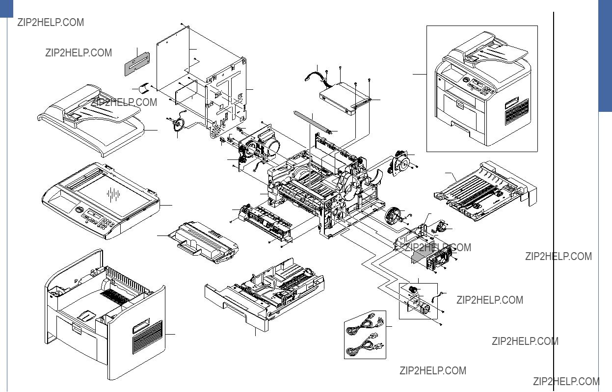
55. Disassembly and Reassembly
5.1 General Precautions on Disassembly
When you disassemble and reassemble compo- nents, you must use extreme caution. The close proximity of cables to moving parts makes proper routing a must.
If components are removed, any cables disturbed by the procedure must be restored as close as possible to their original positions. Before remov- ing any component from the machine, note the cable routing that will be affected.
Releasing Plastic Latches
Many of the parts are held in place with plastic latches. The latches break easily; release them carefully.
To remove such parts, press the hook end of the latch away from the part to which it is latched.
Whenever servicing the machine, you must perform as follows:
1.Check to verify that documents are not stored in memory.
2.Be sure to remove the toner cartridge before you disassemble parts.
3.Unplug the power cord.
4.Use a flat and clean surface.
5.Replace only with authorized components.
6.Do not force
7.Make sure all components are in their proper position.

Precautions
5.2 Front Cover
1. Take out the Cassette.
3. If necessary, remove the Toner Cartridge.

Precautions
5.3 MP Tray Ass'y
1. Open the MP Tray Ass'y
2.Pull the Tray Links from the both side of the Front Cover with a light pressure to the direction of arrow .
3.Apply light pressure to the both side of the MP Tray Ass'y and pull it in the direction of arrow, as shown below.

Precautions
5.4 Rear Cover
1.Open the DIMM Cover from the Left Side Cover in the direction of arrow, as shown below.
3.Remove the four screws securing the Rear Cover and then Release the Rear Cover from the Set.
2. Take out the Duplex Unit.
4.To remove the Face Up Cover, first release the Stopper Strap in the direction of arrow.

Precautions
5.Unlatch the Face Up Cover from the Rear Cover and then release the Face Up Cover, as shown below.
Precautions
5.5 Fuser Ass'y
1.Before you remove the Fuser Ass'y, you should remove:
- Rear Cover (Refer to 5.4)
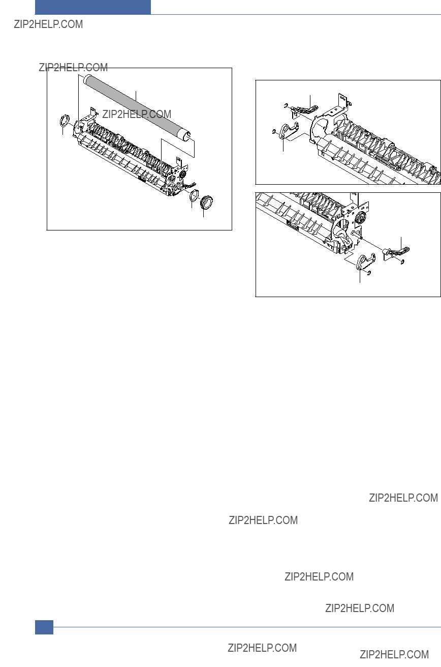
2.Remove the four screws securing the Fuser Ass'y and then pull the Fuser Ass'y.
3.Release the CON Harness and REC Harness from the Thermostat and then remove the three screws securing the Thermostat and remove it.
4.To remove the Halogen Lamp, first release REC Harness from the left side of the Halogen Lamp and then release the CON Harness from the right side of the Halogen Lamp, as shown below.
5.Remove the two screws securing the both side of the Halogen Lamp and then release in the direction of arrow, as shown below.

Precautions
6.Remove the two screws securing the IInput Guide and remove it.
7. Unplug the connector from the Input Guide and remove the one screw securing the Thermistor and remove it.
8.Remove the three screws securing the Idle Gear Bracket and remove it.
9.Remove the one screw securing the Fuser Cover and release the Fuser Cover from the Fuser Frame.
Precautions
10.Release the Fuser Gear and HR Bush and then remove the Heat Roller, as shown below.
11.Remove the Jam Link Lever (L,R) and Jam Holder (L,R) and then remove the Pressure Roller, as shown below.
Precautions
5.6 Side Cover (Left, Right)
1.Before you remove the Side Cover (Left, Right), you should remove:
- Rear Cover (Refer to 5.4)
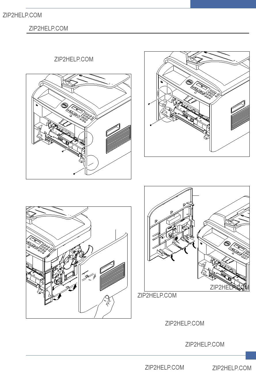
2.Remove the two screws securing the Right Side Cover, as shown below.
4.Remove the two screws securing the Left Side Cover, as shown below.
3.Apply light pressure to the bottom of the Right Side Cover and pull it to the right side in the direction of arrows, as shown below.
5.Apply light pressure to the bottom of the Left Side Cover and pull it to the left side in the direction of arrows, as shown below.
Precautions
6.To remove the DIMM Cover, first open the DIMM Cover (refer to 5.4.1) and then release the DIMM Cover, as shown below.
Notice : Be careful not to damage the hooks when remove the Side Cover (Left, Right).

Precautions
5.7 Scanner Ass'y
1.Before you remove the Scanner Ass'y, you should remove:
-Rear Cover (Refer to 5.4)
-Side Cover (Left, Right) (Refer to 5.6)
2.Remove the two screws securing the Scanner Ass'y, as shown below.
3.Remove the one screw securing the Ground Cable and unplug the four connectors and CCD Cable.
ADF Ground Cable

4. Pull up the Scanner Ass'y, as shown below.
5.Release the ADF Harness from the underneath the Scanner Ass'y.
Service Manual

Precautions
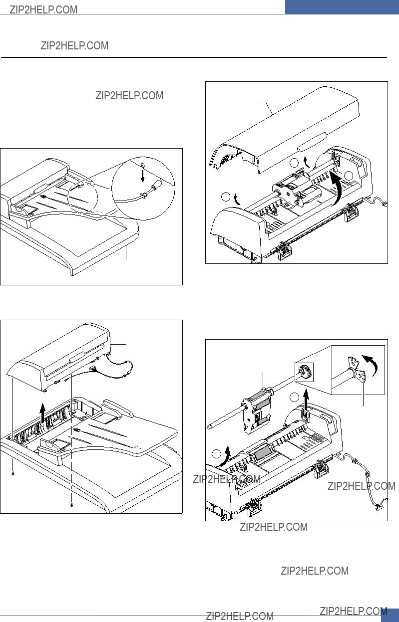
6. Lift the ADF Ass'y upward to remove it.
7.To remove the OPE Unit, first pull the part below the front of the OPE Unit with a light pressure to the direction of arrow.
8.Unplug the three connectors from the OPE PBA, as shown below and then release the Battery.
9. Remove the four screws securing the Scan Upper.
10.Release the four hooks securing the Scan Upper to the Scan Lower and remove it, as shown below.
11. Remove the CCD Cable, as shown below.

Precautions
12. Pull up the CCD Shaft and take out the CCDM.
13.Squeeze the spring to release the tension in the Belt and lift from the pulleys, as shown below.
14.Remove the three screws securing the Scan Motor Ass'y and remove it.
15.If necessary, remove the two screws securing the Scan Motor and remove it, as shown below.
Gear Bracket Ass'y
Scan Motor

Caution : Reassembling CCDM
1)When refitting the Scanner Belt and Belt Spring take care to relocate the tension spring as close to the right side of the CCDM as is possible, as shown below.
2)When refitting the Scan Upper Cover take care to ensure that the Cover Open Switch is not trapped.
Service Manual

Precautions
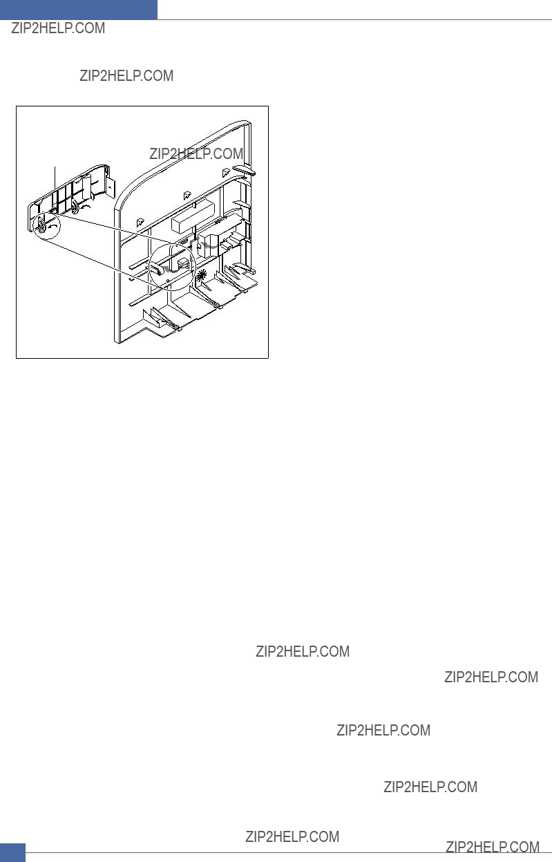
16. Unplug the connector from the Open Sensor Ass'y.
17.Unlatch the Open Sensor and remove it, as shown below.
18. Remove the CCD Holder.
19.Unplug the Harness from the CCD Home Sensor and release the CCD Home Sensor, as shown below.
Precautions
5.8 ADF Ass'y
1.Before you remove the ADF Ass'y, you should remove:
-Rear Cover (Refer to 5.4)
-Side Cover (Left, Right) (Refer to 5.6)
-Scanner Ass'y (Refer to 5.7)
2.Release the ADF Harness from the underneath the Platen Cover Ass'y.
3.Remove the two screws securing the ADF Engine Ass'y and remove it.
Notice : Take care to thread the ADF Harness through the Platen Cover Ass'y.
4. Remove the Open Cover, as shown below.
Notice : When working on the ADF Motor Ass'y take care not to contaminate any of the rubber surfaces with grease.
5.Release the Bush and rotate it until it reaches the slot, as shown below. Then lift the Pick Up Ass'y out.
Service Manual
Precautions
6.Remo the two screws securing the ADF Upper and remove it, as shown below.
Notice : Before removing the ADF Engine Ass'y take great care to note the position of the Ferrite Core and the Motor Harness routing. When refitting the ADF Engine Ass'y ensure that the Harness and Ferrite are properly located and are clear of the Motor Fan and White Bar Clip.
7.Unplug the one connector and remove four screws securing the ADF Motor Ass'y and then remove the one screw securing the Ground Cable, as shown below. Then take out the ADF Motor Ass'y.

Precautions
5.9 OPE Unit
1.Before you remove the OPE Unit, you should remove:
-Rear Cover (Refer to 5.4)
-Side Cover (Left, Right) (Refer to 5.6)
-Scanner Ass'y (Refer to 5.7)
2.Remove the five screws securing the OPE PBA from to the OPE Cover.
4. Remove the Keys from the OPE Cover.
3. Remove the Contact Rubber from the OPE Cover.
Service Manual

Precautions
5.10 Shield Controller Ass'y
1.Before you remove the Shield Controller Ass'y, you should remove:
-Rear Cover (Refer to 5.4)
-Side Cover Left (Refer to 5.6.4)
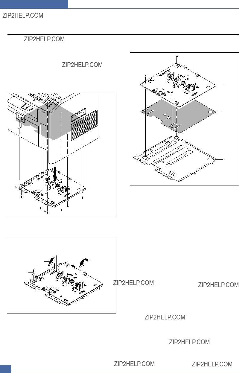
2.Unplug the all connectors and remove the one screw securing the Ground Cable.
3.Remove the five screws securing the Shield Controller Ass'y and remove it.
4.Remove the three screws securing the Main PBA to the Bracket and unplug the Film Cable and then remove the Main PBA.
5. The connectors are located, as shown below.

Precautions
6.Remove the three screws securing the Modem PBA to the Bracket and unplug the Film Cable and then remove the Modem PBA.
7.Remove the two screws securing the Speaker to the Bracket and unplug the connector from the Modem PBA and then remove the Speaker.
Service Manual

Precautions
5.11 Drive Ass'y
1.Before you remove the Drive Ass'y, you should remove:
-Rear Cover (Refer to 5.4)
-Side Cover Left (Refer to 5.6.4)
-Shield Controller Ass'y (Refer to 5.10)
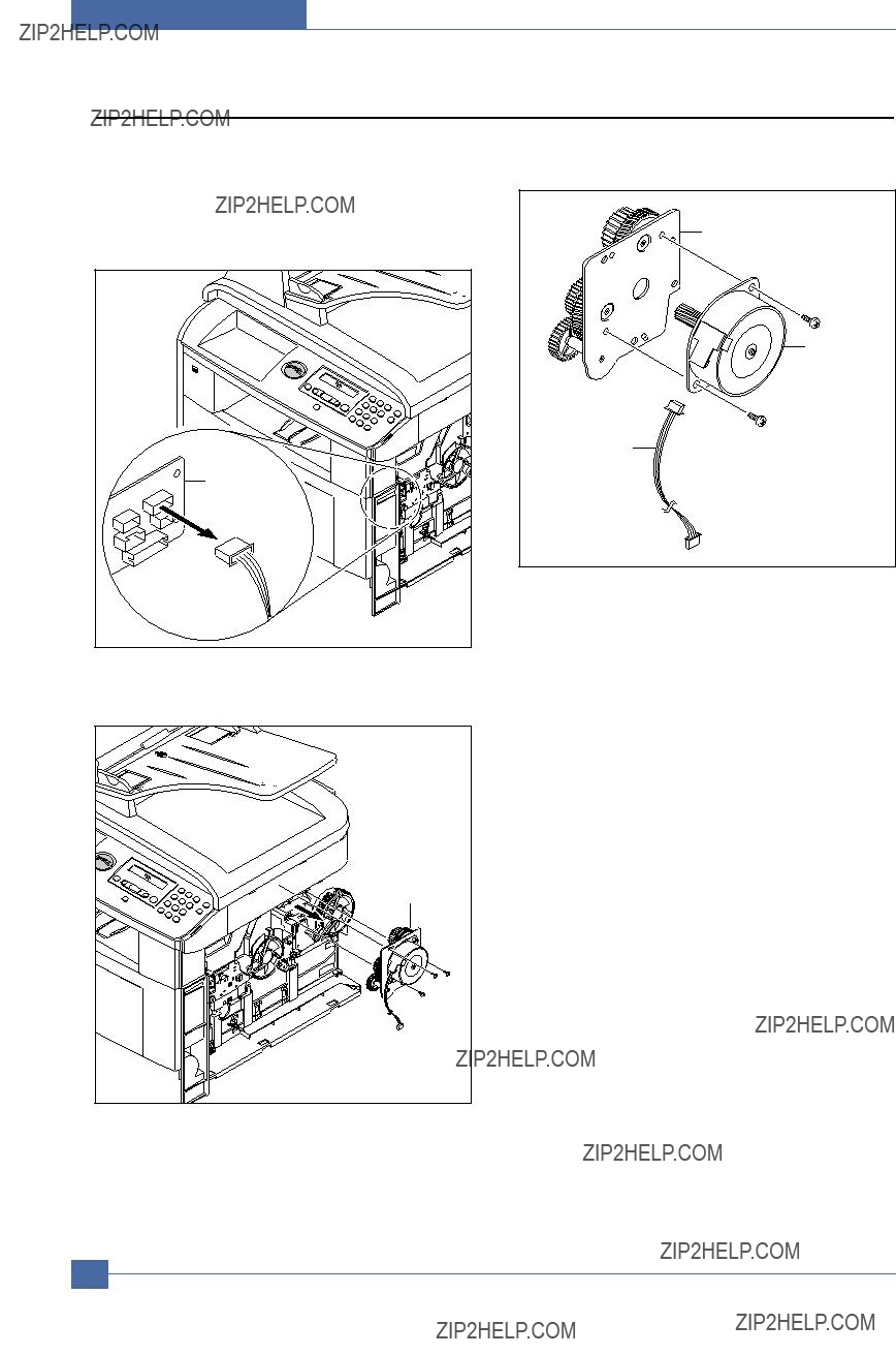
2.Remove the five screws securing the Drive Ass'y and remove it.
3.If necessary, remove the four screws securing the BVDC Motor Ass'y and remove it.
Notice : The six screws have numbers stamped into the Drive Ass'y base plate. When refitting the Drive Ass'y tighten the screws the order they are numbered. Only screws numbered 1 to 5 are fitted at this stage. Screw 6 is fitted when the Shield Controller Ass'y is refitted.

Precautions
5.12 Duplex Drive Ass'y
1.Before you remove the Duplex Drive Ass'y, you should remove:
-Rear Cover (Refer to 5.4)
-Side Cover Right (Refer to 5.6.3)
2.Unplug the connector from the Connection PCB and remove the three screws securing the Duplex Drive Unit and remove it. 

 Connection
PCB
 Duplex Motor
3.If necessary, remove the two screws securing the Duplex Motor and remove it.
Harness
Duplex Motor
Bracket Ass'y
Duplex Drive Ass'y
Service Manual

Precautions
5.13 Shield SMPS Ass'y
1.Before you remove the Shield SMPS Ass'y, you should remove:
-Rear Cover (Refer to 5.4)
-Side Cover Right (Refer to 5.6.3)
-Duplex Drive Ass'y (Refer to 5.12)
2.Unplug the two connectors (HVPS, Fuser).
4.Unplug the connector (AC Inlet) and remove the four screws securing SMPS and remove it.
3.Remove the three screws securing the Shield SMPS Ass'y and remove it.

Precautions
5.14 Connection PCB
2. Unplug the all connectors.
3.Remove the two screws securing the Connection PCB and remove it.
Service Manual
Precautions
5.15 Fuser Drive Ass'y
1.Before you remove the Fuser Drive Ass'y, you should remove:
-Rear Cover (Refer to 5.4)
-Side Cover Right (Refer to 5.6.3)
2.Unplug the connector from the Connection PCB.
4.If necnsary, remove the two screws securing the Step Motor and remove it.
Fuser Exit Bracket Ass'y
Step Motor
Harness
3.Remove the three screws securing the Fuser Drive Ass'y and remove it.

Precautions
Service Manual
Precautions
5.17 Pick Up Roller Ass'y
1. Take out the Cassette.
2.To remove the Pick Up Roller Ass'y, first lift the notch attached to the Pick Up Roller Ass'y from the Shaft, then slide the Pick Up Roller Ass'y from left to right and it will be released completely, as shown below.
3.To remove the Shaft, first release the locker and slide the Shaft from left to right, then lift the notch attached to the Cam so that it's released from the Shaft. Then release the Bush from the Shaft and remove the Shaft from the Duplex Guide Housing, as shown below.

Precautions
5.18 Duplex Guide Housing (With Feed Roller)
1.Before you remove the Duplex Guide Housing, you should remove:
- Pick Up Roller Ass'y (Refer to 5.17)
2.Remove the two screws securing the Duplex Guide Housing.
4. Pull the Feed Roller from the Bushing.
3.Unplug the one connector (Photo Interrupter) and remove the Duplex Guide Housing (with Feed Roller), as shown below.
Service Manual
Precautions
5.19 HVPS Housing
1.Before you remove the HVPS Housing, you should remove:
-Duplex Drive Ass???y (Refer to 5.12)
-Pick Up Roller Ass'y (Refer to 5.17)
-Duplex Guide Housing (Refer to 5.18)
-Unplug the two Connectors (HVPS)
2.Remove the eight screws securing the HVPS Housing, as shown below.
4.If necessary, remove the three screws securing the HVPS and remove it.
3.Unplug the connector for connection PBA & SMPS first. Unplug the other connectors.
 Duplex Motor
Engine
Duplex Guide
Housing
 Connection PBA
& SMPS

Precautions
5.20 Middle Cover Ass'y
1.Before you remove the Middle Cover Ass'y, you should remove:
-Rear Cover (Refer to 5.4)
-Side Cover (Left, Right) (Refer to 5.6)
-Scanner Ass'y (Refer to 5.7)
-Shield Controller Ass'y (Refer to 5.10)
2.Remove the six screws securing the Middle Cover Ass'y and remove it.
3.If necessary, remove the two screws securing the USB Host PBA and remove it.
5.21 Cover Mid Front
1.Before you remove the Cover Mid Front, you should remove:
- Middle Cover Ass'y (Refer to 5.20)
2.Remove the four screws securing the Cover Mid Front and release two hooks in the center. This cover is fragile take care when removing it.

Precautions
5.22 MPF Housing
1.Before you remove the MPF Housing, you should remove:
- Cover Mid Front (Refer to 5.21)
2.Remove the four screws securing the MPF Housing and remove it.
3.To remove the MP Pick Up Ass'y, first lift the notch attached to the left side Stopper so that it's slide the right to left from the Shaft, then left side Idle slid the right to left from the Shaft and take out the MP Pick Up Ass'y, as shown below.
Precautions
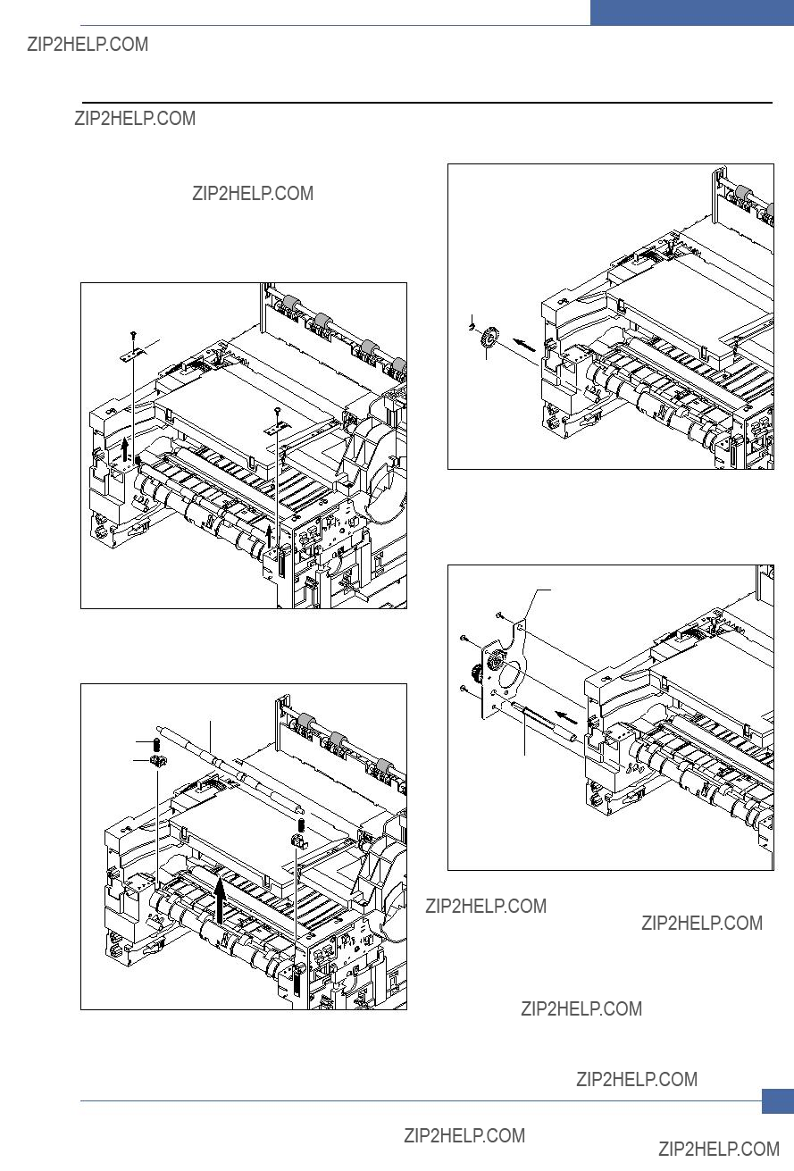
5.23 Feed Roller Parts
1.Before you remove the Feed Roller Parts, you should remove:
-Pick Up Roller Ass'y (Refer to 5.17)
-Duplex Guide Housing (Refer to 5.18)
-Middle Cover Ass'y (Refer to 5.20)
-MPF Housing (Refer to 5.22)
2.Remove the two screws securing the both side of the Guide Paper and then remove the Guides.
3.Pull up the Feed Idle Shaft and the Bushs (with Spring).
4.Release the
5.Remove the three screws securing the Feed Bracket Unit and then remove the Feed Bracket Unit and Feed2 Shaft.
Service Manual
Precautions
6.If necessary, release the three
Idle Gear
Bracket
Retard Gear
T2 Idle Gear
Notice : Be aware of the
7. Remove the Clutch Unit, as shown below.
8.Pull up the Feed1 Roller from the Bushing, as shown below.
Precautions
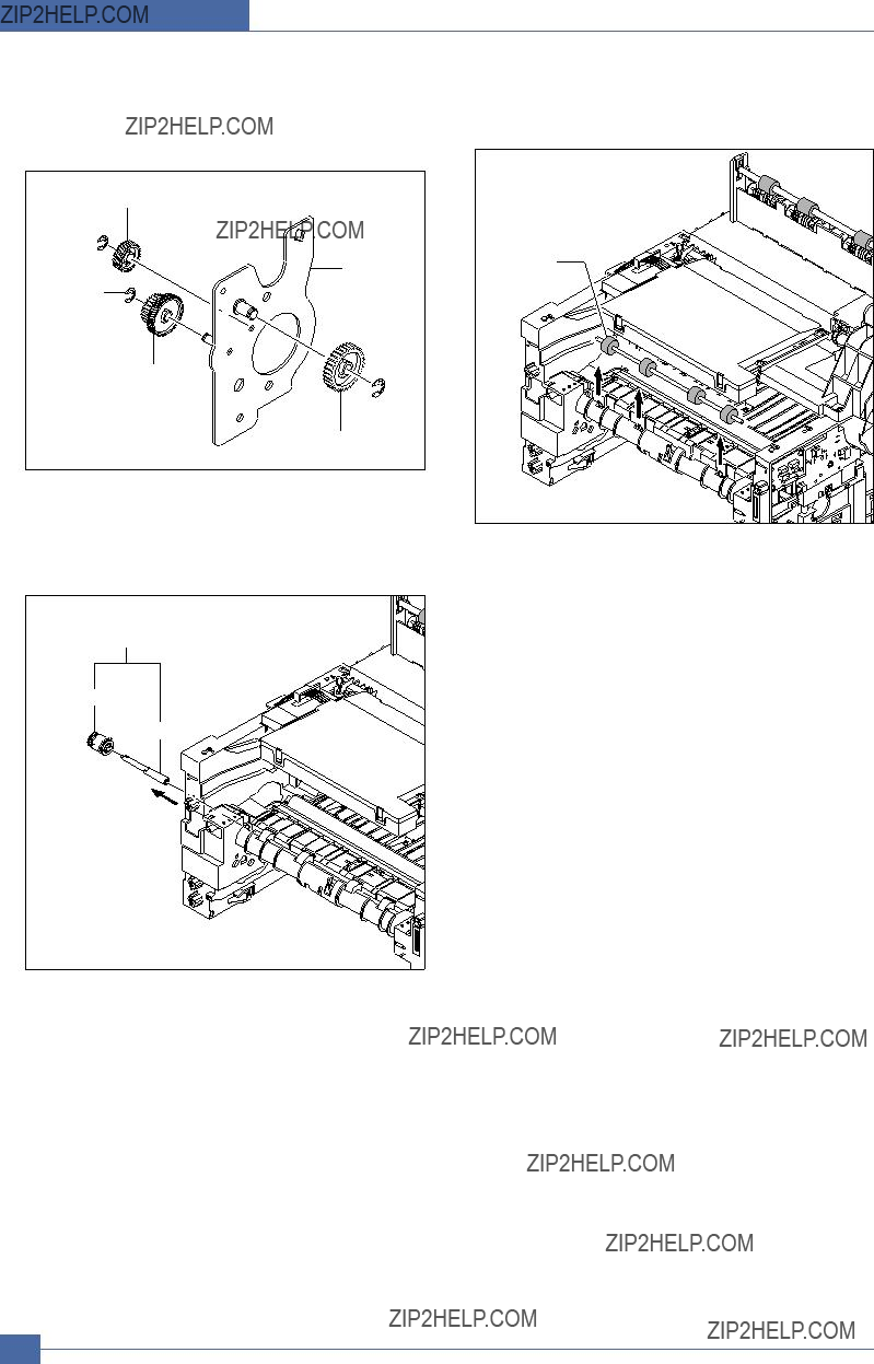
5.24 Pick Up Gear Ass'y & Solenoids
1.Before you remove the Pick Up Gear Ass'y & Solenoids, you should remove:
-Duplex Guide Housing (Refer to 5.18)
-Feed Bracket Unit (Refer to 5.23.5)
2.Release the Pick Up Gear Ass'y and Pick Up Gear Shaft, as shown below.
3.Remove the two screws securing the Manual Solenoid and Feed Solenoid and then remove the Solenoids, as shown below.
5.25 Exit Roller
1.Before you remove the Exit Roller, you should remove:
-Fuser Drive Ass'y (Refer to 5.15)
-Middle Cover Ass'y (Refer to 5.20)
2.Remove the Exit Gear, and release the Bearing at one end then remove the Roller Exit F/Down and Exit Roller Rack, as shown below.

Precautions
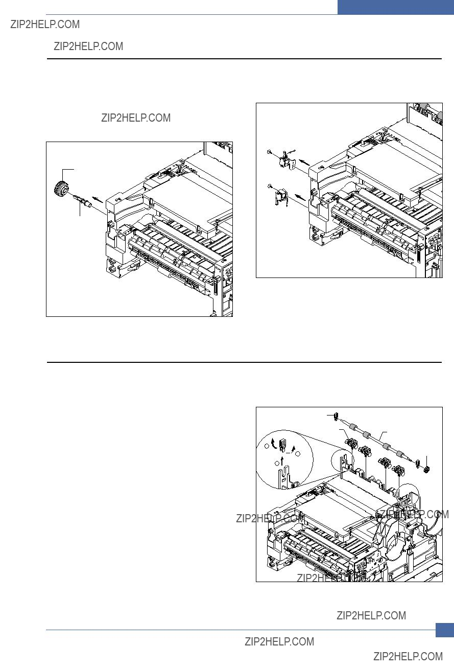
5.26 LSU
1.Before you remove the LSU, you should remove: - Middle Cover Ass'y (Refer to 5.20)
2.Remove the four screws securing the LSU and remove it.
5.27 Terminal PBA
1.Before you remove the CRUM2 PBA, you should remove:
-Middle Cover Ass'y (Refer to 5.20)
-LSU (Refer to 5.26)
2.Remove the one screw securing the CRUM2 PBA and remove it and then release the four Terminals, as shown below.
Notice : Be aware of the Terminals to ensure they are not lost.

Precautions
5.28Transfer Roller Parts
1.To remove the Transfer Roller, first push the TR Holder and then take out the Transfer Roller, as shown below.
Notice : Do not grab the rubber part of the Transfer Roller, it may cause a malfunction due to a foreigen object. Hole the both side of the Transfer Roller when replacing it.
Service Manual
Alignment & Adjustments
66. Alignment and Adjustments
This chapter describes the main functions for service, such as the product maintenance method, the test output related to maintenance and repair, DCU using method, Jam removing method, and so on. It includes the contents of manual.
6.1 Paper path

Alignment & Adjustments
6.2 Clearing Paper Jams
Occasionally, paper can be jammed during a print job. Some of the causes include:
???The tray is loaded improperly or overfilled.
???The tray has been pulled out during a print job.
???The front cover has been opened during a print job.
???Paper was used that does not meet paper specifications.
???Paper that is outside of the supported size range was used.
If a paper jam occurs, LCD window will show it??? s speeds. Find and remove the jammed paper. If you don???t see the paper, open the covers.
Do not use a pinset or a sharp metal tool when removing a jam.
The covering of a metal part can be removed which can cause an electric leakage.
Alignment & Adjustments
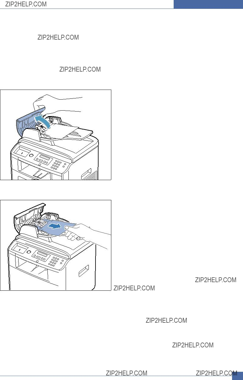
6.2.1 Clearing Document Jams
When a document jams while it passes through the ADF, Document Jam appears on the display.
NOTE: To prevent document jams, use the document glass for thick, thin or mixed documents.
1. Remove the remaining documents from the ADF.
If the document is jammed in the paper feed area:
a. Open the ADF cover.
c.Close the ADF cover. Then reload the document into the ADF.
b. Remove the document by gently pulling it out.
Alignment & Adjustments
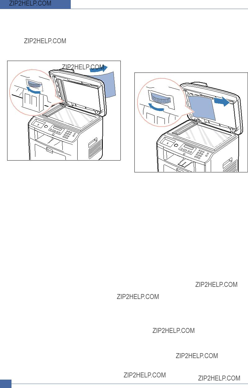
If the document is jammed in the paper exit area:
a.Open the document cover and turn the release knob to remove the misfed documents from the document document output tray.
b.Close the document cover. Then load the documents back into the ADF.
2.If you cannot see the paper or the paper does not move when you pulled, open the document cover.
3.Turn the release knob so that you can easily seize the misfed document, and remove the document from the roller or the feed area by carefully pulling it gently to the right.
4.Close the document cover. Then load the documents back into the ADF.

Alignment & Adjustments
6.2.2 Clearing Jams in the Paper Paths
When a paper jam occurs, Paper Jam appears on the display . Refer to the table below to locate and clear the paper jam.
To avoid tearing the paper, pull the jammed paper out gently and slowly. Follow the steps below to clear the jam.
6.2.3 Paper Feed Jam (tray 1)
1.Open and close the front cover. The jammed paper automatically exits the printer. If the paper does not exit, go to the next step.
2.Pull the paper tray open.
3. Remove the paper by gently pulling it straight out.
If you cannot see the paper or the paper does not move when pulled, check the fuser area. For more information, see "Fuser Area Jam".
4.Insert the paper tray into the printer until it snaps into place.
Printing automatically resumes.

Alignment & Adjustments
6.2.4 Paper Feed Jam (optional tray 2)
1.Pull the optional tray 2 open.
2.Remove the jammed paper from the printer.
If you cannot see the paper in this area or the paper does not move when pulled, go to the next step.
3.Pull the tray 1 half.
4.Pull the paper straight up and out.
6.2.5 Bypass tray Jam
1.If the paper is not feeding properly, pull the paper out of the printer.
2. Open and close the front cover to resume printing.

Alignment & Adjustments
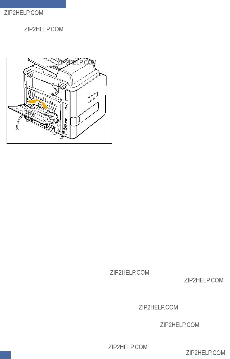
6.2.6 Fuser Area Jam
NOTICE: The fuser area is hot. Take care when removing paper from the printer.
1.Open the front cover and lightly pull the toner cartridge straight out.
2. Remove the paper by gently pulling it straight out.
3.Replace the toner cartridge and close the front cover . Printing automatically resumes.
6.2.7 Paper Exit Jam
1.Open and close the front cover. The jammed paper automatically exits the printer.
If the paper does not exit, go to the next step.
2.Gently pull the paper out of the output tray.
3.If you cannot see the paper in the output tray or the paper does not move when pulled, open the rear cover.
4.If you see the jammed paper, push the two blue pres- sure levers up and remove the paper.
If you do not see the paper, go to the next step.

Alignment & Adjustments
5.Release the blue strap, the rear cover stopper, and fully open the rear cover, as shown.
6. Unfold the duplex guide fully.
7.While pushing the fuser lever to the right, open the fuser door.
NOTE: Make sure to unfold the fuser guide before opening the fuser door or you may damage the fuser door.
8.Pull the jammed paper out.
If the jammed paper does not move when you pull, push the two blue pressure levers up to loosen the paper, and then remove it.
9.Return the levers, fuser door, rear cover stopper, and duplex guide to their original position.
10.Close the rear cover.
Printing automatically resumes.

Alignment & Adjustments
6.2.8 Duplex Jam 0
1. Pull the duplex unit out of the printer.
2. Remove the jammed paper from the duplex unit.
If the paper does not come out with the duplex unit, remove the paper from the bottom of the printer.
3. Push the duplex unit to the printer.
CAUTION: If you do not push the duplex unit in correctly, a paper jam may occur.
Alignment & Adjustments
6.2.9 Duplex Jam 1
1.Open the rear cover.
2.Unfold the duplex guide fully.
3.Pull the jammed paper out.
4.Return the duplex guide and close the rear cover . Printing automatically resumes.
Alignment & Adjustments
6.3 User Mode(Dell Laser MFP1815dn)
The table in the bellow explains the possible setting functions by user . The details about the ways to use are explained in the user manual.
In the service manual, the items are about the possible
Service Manual
Alignment & Adjustments
6.4 Tech Mode
6.4.1 How to Enter Tech Mode
In service (tech) mode, the technician can check the machine and perform various test to isolate the cause of a malfunction.
While in Tech mode, the machine still performs all normal operations.
To enter the Tech mode
To enter the Tech mode, press 


 in sequence, and the LCD briefly displays ???TECH???, the machine has entered service (tech) mode.
6.4.2
MFP1815dn

Alignment & Adjustments
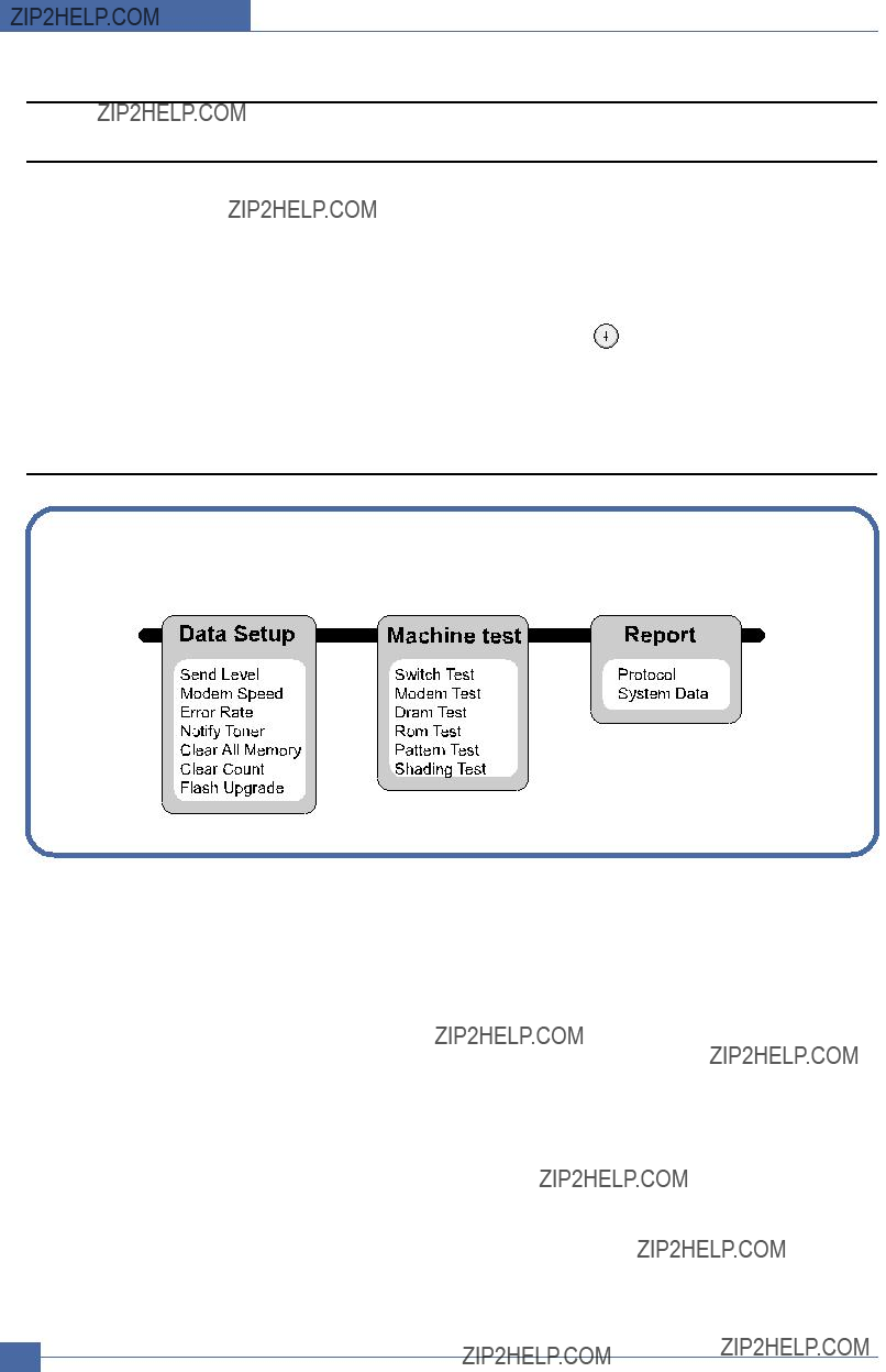
6.4.3 Data Setup
SEND LEVEL
You can set the level of the transmission signal. Typically, the Tx level should be under
Caution : The Send Fax Level is set at the best condition in the shipment from factory. Never change settings arbitrarily.
DIAL MODE
This function can choose dial method. *Default : Dial(Dial/Pulse)
MODEM SPEED
You can set the maximum modem speed.
Communication is done with modem speed automatically set at lower speed when communicating with a slow - er speed modem since communication is done on the standard of the side where modem speed is low for transmission/reception. It is best set 33.6Kbps as default setting.
ERROR RATE
When the error rate is about exceed the set value, the Baud rate automatically adjusts to 2400 bps. This ensures that the error rate remains below the set value.
You can select the rate between 5% and 10%.
CLEAR ALL MEMORY
The function resets the system to factory default settings.
This function is used to reset the system to the initial value when the product is functioning abnor- mally . All the values are returned to the default values, and all the information, which was set by the user, will be erased.
< Method >
1.Select the [MEMORY CLEAR] at the TECH MODE.
2.Push the ENTER button.
3.Select you country. (There are four country groups. Refer to the table below .)
4.Push the ENTER button then it will clear all memory .
NOTICE : Always perform a memory clear after replacing the main board. Otherwise, the system may not operate properly.

Alignment & Adjustments
FLASH UPGRADE
The Firmware Upgrade function and has two methods, Local and Remote.
(1) Local Machine
??? RCP(Remote Control Panel) mode
This method is for Parallel Port.or USB Port Connect to PC and activate RCP(Remote Control Panel) to upgrade the Firmware.
< Method >
How to Update Firmware using RCP
1.Connect PC and Printer with Parallel Cable or USB Cable.
2.Execute RCP and select Firmware Update.
3.Search Firmware file to update with Browse Icon.
4.Click Update icon, firmware file is transmitted to Printer automatically and printer is initialized when it fin - ished.
5.Click Refresh icon and check what is updated.
???DOS Command mode
This method is just for Parallel Port. Connect to PC with Parallel cable and enter DOS Command to upgrade the Firmware.
< Method >
1.The first of all, need the files : down.bat, down_com.bin, fprt.exe, and Rom File: file name for upgrade.Save the files in the same folder.
2.In the DOS, input as below and push the enter key . Then, it will be automatically upgraded.
3.There are two commands for the conditions of product. * When the product is in idle condition down "rom file"
* When the product is in Ready condition (TECH MODE ??? DATA SETUP ??? FLASH UPGRADE??? LOCAL)
fprt "rom file"
4.Do not turn off the power while upgrading process.
(2)Remote FAX
This is a function that a fax with the latest firmware sends files to a fax in long distance through telephone line.
< Method >
1. Operate a fax with the latest firmware to prepare it being upgrade.
(TECH MODE ??? DATA SETUP??? FLASH UPGRADE??? REMOTE) 2. Input the fax number, which needs to be upgraded.
(Several faxes can be upgrade at the same time. In this case, enter the each fax number .) 3. After push the enter button, send the firmware file by calling to the appointed number .
(Around 10~15 minutes needs to send the file.)
< Caution >
1.sending and receiving fax must be the same model.
2.A sending fax must be set up as ECM mode, and a receiving memory must be set up as 100%. If not, the function operates abnormally.
Alignment & Adjustments
6.4.4 Machine Test
SWITCH TEST
Use this feature to test all keys on the operation control panel. The result is displayed on the LCD window each time you press a key.
MODEM TEST
Use this feature to hear various transmission signals to the telephone line from the modem and to check the modem. If no transmission signal sound is heard, it means the modem part of the main board malfunctioned.
DRAM TEST
Use this feature to test the machine's DRAM. The result appears in the LCD display. If all memory is working normally, the LCD shows << O K >>
ROM TEST
Use this feature to test the machine'S ROM. The result and the software version appear in the LCD display.
???FLASH VER : 1.00 V
???ENGINE VER :1.00V
PATTERN TEST
Using this pattern printout, you can check if the printer mechanism is functioning properly . It is needed in the production progress. Service person doesn't need to use it.
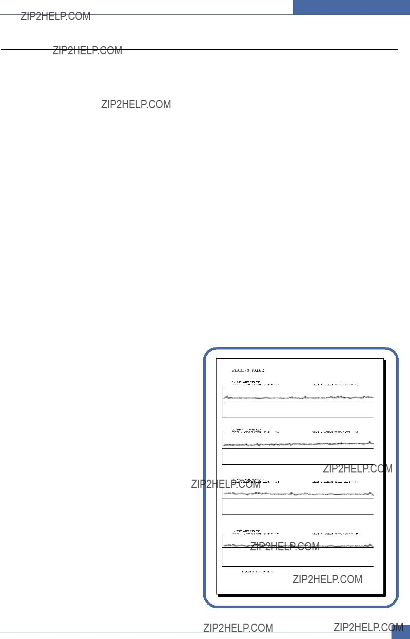
SHADING TEST
The function is to get the optimum scan quality by the specific character of the CCD(Charge Coupled Device). If the copy image quality is poor , perform this function to check the condition CCD unit.
< Method >
1. Select the [ADJUST SHADING] at the
TECH MODE.
2. Push the SET UP button then an image will be scanned.
3.After the scan, CCD SHADING PRO- FILE will be print out.
4. If the printed image is dif ferent to the image, the CCD is defect.
NOTICE : When you test CCD, make sure that the cover is closed.
Service Manual

Alignment & Adjustments
6.4.5 Report
PROTOCOL LIST
This list shows the sequence of the CCITT group 3 T.30 protocol during the most recent sending or receiving operation. Use this list to check for send and receive errors. If a communication error occurs while the machine is in TECH mode, the protocol list will print automatically.
SYSTEM DATA
This list provides a list of the user system data settings and tech mode settings.

Alignment & Adjustments
6.5 Engine Test Mode
The Engine Tests Mode supplies useful functions to check the condition of the engine. It tests the condition of each device and displays the result of the test on the LCD. It is classified into 5 functions (0~4), and are shown below .
Outline
-In order to enter ???Engine Test ??? mode,,the method should be especial because this mode is developed for related engineers, not for users
-After Entering the mode,the message,???Engine Test Mode ??? is displayed..
-On the mode,an engineer should press the ???Menu Key=>#=>1=>9=>3=>1 ??? to search each function he would like to test..
-Turn the power off,after the test is entirely end.
6.5.1 To enter the Engine Test Mode
To enter the Engine Test mode
Press 


 in sequence, and the LCD briefly displays ???Engine Test???, the machine has entered Engine Test Mode.
6.5.2 Diagnostic
Service Manual

Alignment & Adjustments
6.5.3 Detail Description(Engine Test Mode)

Alignment & Adjustments
6.6 Identify Sale Date
This function confirms the date that consumer bought product and used the product for the first time. When the consumer first operate the machine, it will start a scan and page count.
The time the machine was first used is remembered.
These settings are are remembered after memory delete (Clear All Memory).
< Method >
Press MENU, #, 1, 9, 3, # in sequence.Firmware version is displayed on LCD.
Press 1( in the number keypad) : The LCD display shows "Updated date"
Press 2( in the number keypad) : The LCD display shows "Product first use date"
Service Manual

Alignment & Adjustments
6.7 Consumables and Replacement Parts
The cycle period outlined below is a general guideline for maintenance.
The example list is for an average usage of 50 transmitted and received documents per day. Environmental conditions and actual use will may vary.
The cycle period given below is for reference only.
Alignment & Adjustments
6.8 Abnormal Image Printing and Defective Roller
If abnormal image prints periodically, check the parts shown below.
Service Manual

Alignment & Adjustments
6.9 Error Messages

Alignment & Adjustments
Service Manual

Troubleshooting
77. Troubleshooting
7.1 Paper Feeding Problems
7.1.1 Wrong Print Position
??? Description Printing begins when the paper is in the wrong position.
7.1.2 JAM 0
5.If the paper feeds into the printer rand Jam 0 occurs, cheek diagnostic mode to check

Troubleshooting
7.1.3 JAM 1
1.Recording paper is jammed in front of or inside the fuser .
???Description 2. Recording paper is stuck in the discharge roller and in the fuser just after passing through the
Empty Sensor
7.1.4 JAM 2
1.Recording paper is jammed in front of or inside the fuser .
???Description 2. Recording paper is stuck in the discharge roller and in the fuser just after passing through the
Empty Sensor

Troubleshooting
7.1.5
7.1.6 Paper rolled in the fuser
??? Description If contaminated at intervals of 57mm on the back of a paper .

Troubleshooting
7.1.7 Paper rolled in the OPC
7.1.8 Defective ADF
??? Description ADF (Automatic document Feeder) is not properly operated.

Troubleshooting
7.2. Printing Problems (malfunction)

Troubleshooting
7.2.3 Not functioning of the fuser gear due to melting away
7.2.4 Paper Empty
7.2.5 Paper Empty without indication

Troubleshooting
7.2.6 Door Open
7.2.7 No Beep on when the Door is open
Troubleshooting
7.2.8 Defective Motor operation
7.2.9 No Power

Troubleshooting
7.2.10 Vertical Line Getting Curved

Troubleshooting
7.3 Printing Quality Problems
7.3.1 Vertical Black Line and Band
??? Description
Digital Printer
Digital Printer
Digital Printer
Digital Printer
Digital Printer
1.Straight thin black vertical line occurs in the printing.
2.Dark black vertical band occur in the printing.
7.3.2 Vertical White Line
??? Description
Digital Printer
Digital Printer
Digital Printer 
Digital Printer
Digital Printer
White vertical voids in the image.

Troubleshooting
7.3.3 Horizontal Black Band
??? Description
Digital Printer
Digital Printer
Digital Printer
Digital Printer
Digital Printer
1. Dark or blurry horizontal stripes occur in the printing periodically . (They may not occur periodically.)
7.3.4 Black/White Spot
??? Description
 Digital Printer
Digital Printer
Digital Printer 
Digital Printer
Digital Printer
1.Dark or blurry black spots occur periodically in the printing.
2.White spots occur periodically in the printing.
Service Manual

Troubleshooting
7.3.5 Light Image
??? Description
Digital Printer
Digital Printer
Digital Printer
Digital Printer
Digital Printer
The printed image is light, with no ghost.
7.3.6 Dark Image or a Black
??? Description
Digital Printer
Digital Printer
Digital Printer
Digital Printer
Digital Printer
The printed image is dark.
(Perform Engine Test Mode : Diagnostic code 4 HVPS check.)
Troubleshooting
7.3.7 Uneven Density
??? Description Print density is uneven between left and right.
3.The toner level is not even on the devel - oper roller due to the bad blade.
7.3.8 Background
??? Description
Digital Printer
Digital Printer
Digital Printer
Digital Printer
Digital Printer
Light dark background appears in whole area of the printing.
Service Manual

Troubleshooting
7.3.9 Ghost (1)
??? Description Ghost occurs at 75.5 mm intervals of the OPC drum in the whole printing.
Digital Printer
Digital Printer
Digital Printer
Digital Printer
Digital Printer
Digital Printer
mm 5.75
7.3.10 Ghost (2)
Digital Printer
Digital Printer
Digital Printer
Digital Printer
Digital Printer
Digital Printer
mm 5.75

Troubleshooting
7.3.11 Ghost (3)
??? Description
Digital Printer
Digital Printer
Digital Printer
White ghost occurs in the black image printing at 35.2 mm intervals.
7.3.12 Ghost (4)
??? Description Ghost occurs at 77.8 mm intervals.
Digital Printer
Digital Printer
Digital Printer
Digital Printer
Digital Printer
Digital Printer
mm 8.77
7.3.13 Stains on the front of the page
??? Description
Digital Printer
Digital Printer
Digital Printer
Digital Printer
Digital Printer
The background on the face of the printed page is stained.
Service Manual

Troubleshooting
7.3.14 Stains on back of the page
??? Description
Digital
Digital Pri 
Digital Printer
Digital Printer
Digital Printer
The back of the page is stained at 47.1 mm intervals.
7.3.15 Blank Page Print out (1)
??? Description
Digital Printer
Digital Printer
Digital Printer
Digital Printer
Digital Printer
Blank page is printed.
7.3.16 Blank Page Print out (2)
1. Blank page is printed.
??? Description 2. One or several blank pages are printed.
3. When the printer turns on, several blank pages print.

Troubleshooting
7.4 Fax & Phone Problems
7.4.1 No Dial Tone
??? Description While
7.4.2 Defective MF DIAL
??? Description The MF DIAL is not functioning.
Notes:
Product supports the MF DIAL type only.
Service Manual
Troubleshooting
7.4.3 Defective FAX FORWARD/RECEIVE
??? Description The FAX FORWARD/RECEIVE is not functioning.
7.4.4 Defective FAX FORWARD
??? Description RECEIVE is functioning, but FORWARD is not functioning or the received data are broken.
2.Check the RECEIVE condition by trying to forward a FAX to another fax machine from the forwarding side FAX.
3.Check if the telephone line connected to the Product is contaminated or gets stripped off or down.

Troubleshooting
7.4.5 Defective FAX RECEIVE (1)
??? Description FORWARD is functioning, but RECEIVE is not functioning or the received data are broken.
7.4.6 Defective FAX RECEIVE (2)
7.4.7 Defective FAX RECEIVE (3)
??? Description The phone is ringing continuously, but it cannot receive.
Service Manual

Troubleshooting
7.4.8 Defective FAX RECEIVE (4)
??? Description The received data is reduced by more than 50% in the printing.
7.4.9 Defective Automatic Receiving
??? Description The automatic receiving function is not working.

Troubleshooting
7.5 Copy Problems
7.5.1 White Copy
7.5.2 Black Copy
Service Manual

Troubleshooting
7.5.3 Abnormal noise
7.5.4 Defective Image Quality

Troubleshooting
7.6 Scanning Problems
7.6.1 Defective PC Scan
7.6.2 Defective Image Quality of PC Scan
??? Description The image PC scanned is not clear or bad.
Service Manual

Troubleshooting
7.7 Toner Cartridge Service
It is not guaranteed for the default caused by using other toner cartridge other than the cartridge supplied by the or caused by
7.7.1 Precautions on
Excessive exposure to direct light more than a few minutes may cause damage to the cartridge.
7.7.2 Service for the Life of Toner Cartridge
If the printed image is light due to the life of the toner , you can temporarily improve the print quality by redistributing the toner(Shake the toner cartridge), however, you should replace the toner cartridge to solve the problem thoroughly .
7.7.2. 1 Redistributing Toner
When the toner cartridge is near the end of its life, white streaks or light print occurs. The LCD displays the warning mes- sage, ???Toner Low.??? You can temporarily reestablish the print quality by redistributing the remaining toner in the cartridge.
2. Lightly pushing the used cartridge down, pull it out.
4.Save the box and the cover for shipping. Slide the new toner cartridge in until it locks into place.
Note : Help the environment by recycling your used toner car- tridge. Refer to the recycling brochure packed with the toner cartridge for details.
5. Close the front cover.
7.7.3 Service for Judgement of Inferior Expendables and the Standard of Guarantee
Please refer to User's Manual or Instructions on Fax/Printer Expendables SVC for the judgement of inferior expend - ables and the standard of guarantee besides this service manual.

Troubleshooting
7.7.4 Signs and Measures at Poor toner cartridge
Service Manual

Troubleshooting

Troubleshooting
Service Manual
Troubleshooting
7.8 Network Problems Troubleshooting
7.8.1 General Problems

Troubleshooting
7.8.2 Macintosh Problems
7.8.3 Windows Problems
Service Manual

Troubleshooting
7.8.4 SyncThru Installation Problems
Manual Service

6
5


3
Ass'y Cover 2.8
List Parts & View Exploded

Exploded View & Parts List
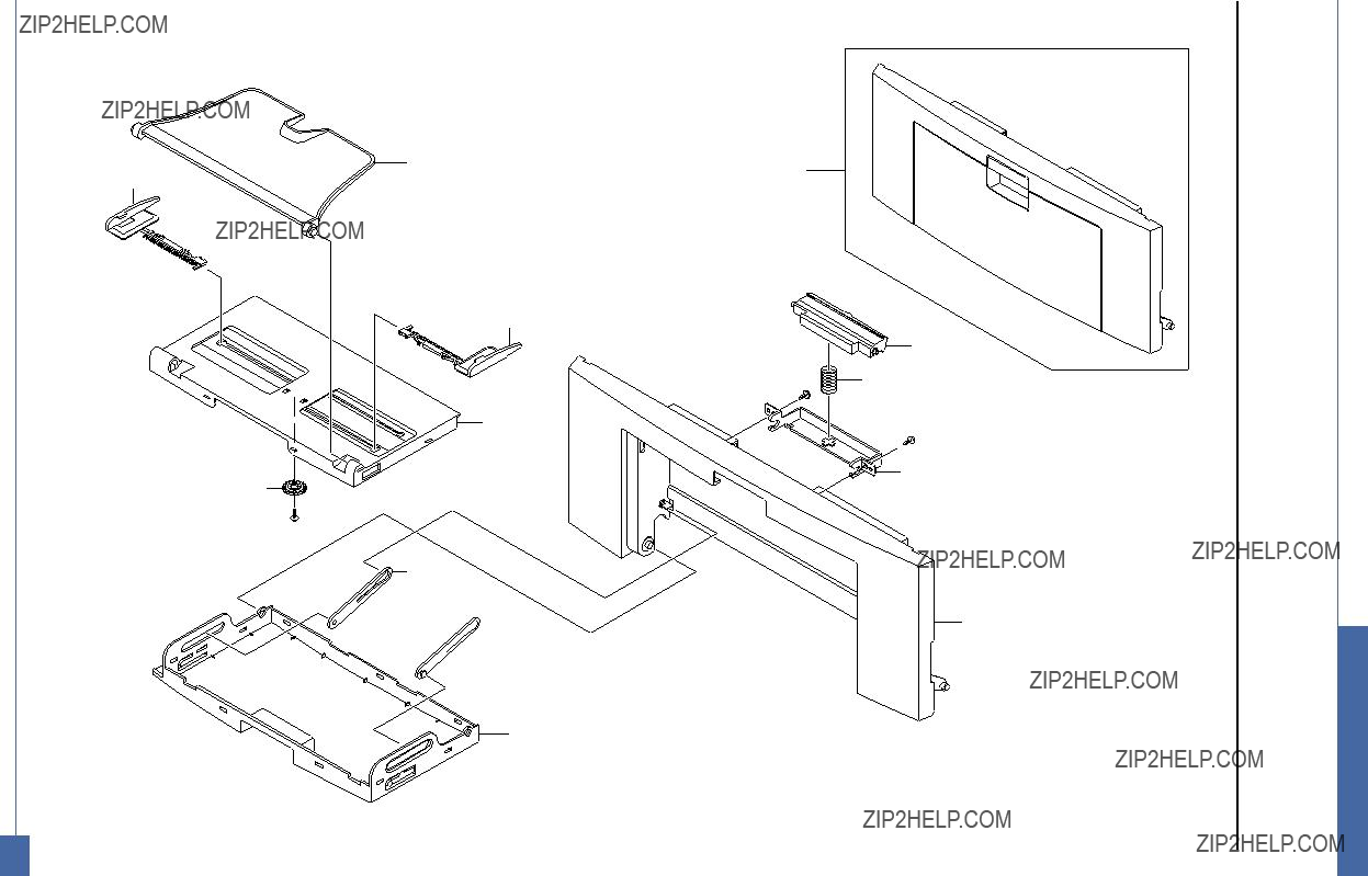
8.3 Middle Cover Ass'y
5
4


 6
6
3
1
6


 2
2
Manual Service
11
6
7
8
9
10

 10
10
5
0
4
3
2
1
Ass'y Cover Front 4.8
List Parts & View Exploded

Manual Service
4
5
0
6
3
1
8
7
2
Ass'y Cover Rear 5.8
List Parts & View Exploded

Exploded View & Parts List
8.7 Fuser Drive Ass'y
0
53
5 8
7 6
1
2
4
9

Manual Service
List Parts & View Exploded

Ass'y MP 9.8
List Parts & View Exploded

Manual Service
3
Ass'y ADF 10.8
List Parts & View Exploded

Exploded View & Parts List
8.11 Cover Platen Ass'y
Exploded View & Parts List
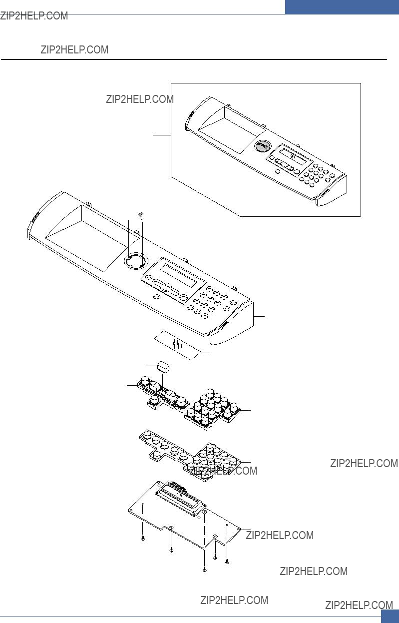
8.12 OPE Unit
0
 2
2
1
3
5
4
6
7
8
Service Manual

Exploded View & Parts List
8.13 Scanner Ass'y
1


2
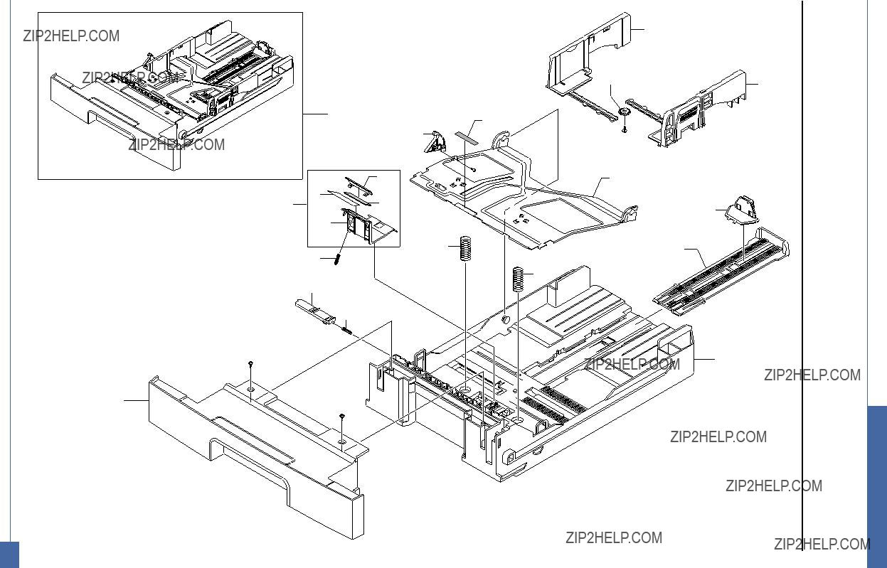
Ass'y Cassette 14.8
10
15
Manual Service
List Parts & View Exploded

Manual Service
Ass'y Fuser 15.8
List Parts & View Exploded

??
??
??
??
??
??
??
??

Block Diagram
99. Block Diagram
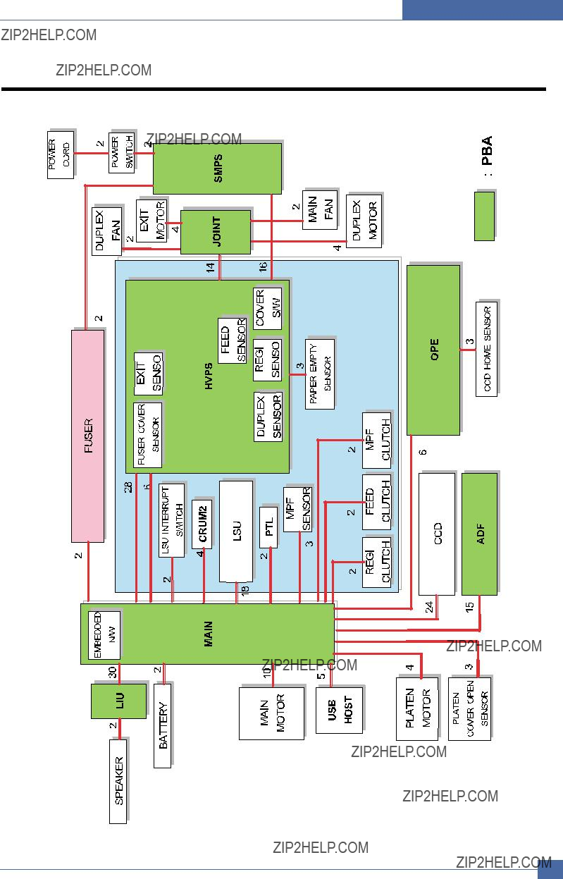
Connection Diagram
1010. Connection Diagram
Service Manual
Dell 1815dn - recommended spare part list
17 Oct 2006
Notes
CRU : Customer Replaceable Units - refers to parts that can easily be replaced by the customer without sending an onsite technician.
FRU : Field Replaceable Unit - a part that can be replaced or added by onsite technician.