???If you have a grounded three-prong receptacle, proceed as follows.
???Rotate choke lever to FULL position.
???Connect power cord to switch box on dash panel. Plug the other end of power cord into a three-prong 120-volt, grounded, AC receptacle.
???Push starter button to crank engine. As you crank the engine, move choke lever to FULL choke position.
???When engine starts, release starter button, and move choke gradually to OFF. If engine falters, move choke immediately to FULL and then gradually to OFF.
???When disconnecting the power cord, always unplug from the three-prong receptacle first, and then from the snow thrower.
Recoil Starter
???Rotate choke lever to FULL choke position (cold engine start).
???If engine is warm, place choke in OFF position instead of FULL.
???Push primer button two or three times for cold engine start.
???If engine is warm, push primer button only once.
NOTE: Always cover vent hole in primer button when pushing. Additional priming may be necessary for first start if temperature is below 15 degrees Fahrenheit.
???Grasp starter handle and pull rope out slowly, until it pulls slightly harder. Let rope rewind slowly.
???Pull starter handle rapidly. Do not allow handle to snap back. Allow it to rewind slowly while keeping a firm hold on the starter handle.
???As engine warms up and begins to operate evenly, rotate choke lever slowly to OFF position. If engine falters, return to FULL choke, then slowly move to OFF position.
To Stop Engine
???To stop engine, turn ignition key counter-clockwise. Disconnect the spark plug wire from the spark plug to prevent accidental starting while equipment is
unattended.
To help prevent possible freeze-up of starter, proceed as follows:
???Run engine for a few minutes before stopping to help dry off any moisture on the engine.
???Electric Starter: Connect power cord to switch box on engine, then to 120 volt AC receptacle. With the engine running, push starter button and spin the starter for several seconds. The unusual sound made by spinning the starter will not harm engine or starter. Disconnect the power cord from receptacle first, and then from switch box.
???Recoil Starter: With engine running, pull starter rope with a rapid, continuous full arm stroke three
or four times. Pulling the starter rope will produce a loud clattering sound, which is not harmful to the engine or starter.
???Wipe all snow and moisture from the carburetor cover in the area of the control levers. Also, move control levers back and forth several times. Leave throttle control lever in the STOP or OFF position. Leave choke control in the FULL choke position.
???Remove ignition key and disconnect spark plug wire to prevent accidental starting.
Operating the Snow Thrower
???Adjust the upper discharge chute up or down as shown in Figure 7. You will have to loosen the hand knob to adjust the upper chute, and then retighten after correct adjustment is reached.
???Use the chute crank to position the discharge chute in order to discharge snow with the wind.
???After making sure no bystanders or obstacles are in front of the unit, engage the auger control handle. As the snow thrower starts to move, maintain a firm hold on the handle, and guide the snow thrower along the path to be cleared.
???Release the auger control handle to stop the snow throwing action and the forward motion.
Figure 7
Operating Tips
???Discharge snow downwind whenever possible. Slightly overlap each previously cleared path.
???Lifting up on the handle will allow the rubber on the augers to propel the snow thrower forward. Pushing downward on the handle will raise the augers off the ground and stop forward motion.
NOTE: Excessive upward pressure on the handle will result in premature wear on the rubber auger blades which would not be covered by warranty.
???Run the engine for a few minutes before stopping to help dry any moisture on the engine.
???Clean the snow thrower thoroughly after each use.
WARNING: Muffler, engine and surrounding areas become hot and can cause a burn. Do not touch.


 DANGER

 Lower Chute


 Hand Knob
 Spark Plug


 Shave Plate


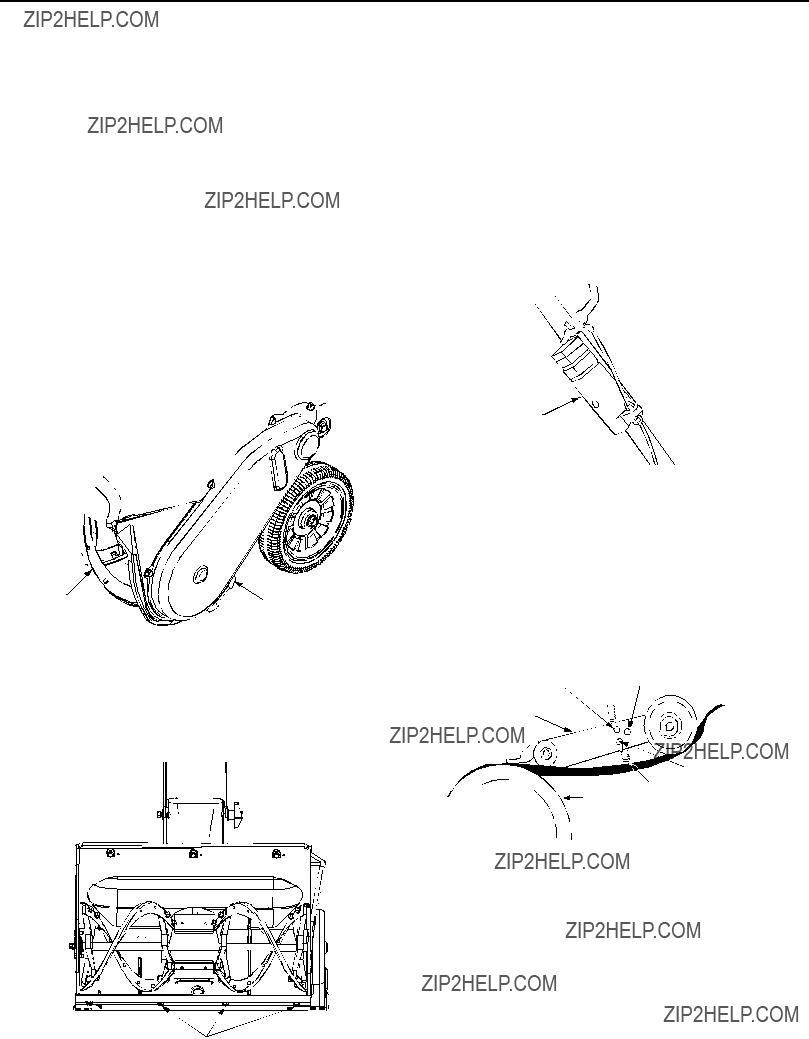


 Hole
Hole Cable
Cable


 Hex
Hex Hex Screw


 Belt Cover


 15
15


