11.0 Horsepower

30 Inch Dual Stage

120V, Electric Start

SNOW THROWER

MODEL NO. 536.881130

Caution:

Read and follow all Safety Rules and Operating Instructions before first use of this product.

a a 0 ll a

g

SEARS, ROEBUCK AND CO., Hoffman Estates, IL 60179 U.S.A.

F-001060J 08/25/99I

i_'_Jnl= L'_J_Ko]LrI_;Iii_"]

LIMITED TWO-YEAR WARRANTY ON CRAFTSMAN SNOW THROWER

For two years from the date of purchase, when this Craftsman Snow thrower is madntained, lubricated, and tuned up according to the operating and maintenance instructions in the owner'smanual, Craftsman will repair, free of charge, any defect in material or workman-

ship.

If this Craftsman Snow thrower is used for commercial or rental purposes, this warranty ap- plies for only 90 days from the date of purchase.

This warranty does not cover the following:

Items which become worn dudng normal use, such as spark plugs, drive belts and shear pins.

Repair necessaP/because of operator abuse or negligence, including bent crankshafts and the failure to maintain the equipment according to the instructions contained in the owner's manual.

WARRANTY SERVICE IS AVAILABLE BY RETURNING THE CRAFTSMAN SNOW

THROWERTO THE NEAREST CRAFTSMAN SERVICE CENTER/DEPARTMENT IN

THE UNITED STATES. THIS WARRANTY APPLIES ONLY WHILE THIS PRODUCT IS

IN USE IN THE UNITED STATES.

This warranty gives you specific legal rights, and you may also have other rights which may vary from state to state.

Sears, Roebuck and Co., D617WA, Hoffman Estates. IL 60179

IT MEANS-- ATTENTION!!! BECOME ALERTI!! YOUR SAFETY IS INVOLVED.

,_ LOOK FOR THIS SYMBOL TO POINT OUT IMPORTANT SAFETY PRECAUTIONS.

theWARNING:spark plugAlwayswire anddisconnectplace it where It cannot make contact

with spark plug to prevent accidental starting during: Preparation, Mainte- nance, or Storage of you snow thrower.

IMPORTANT: Safety standards require oper- ator presence controls to minimize the risk of in- jury. Your snow thrower is equipped with such controls. Do not attempt to defeat the function

of the operatorpresencecontrolunder any cir- cumstances.

TRAINING

1.Read the operating and service instruction manual carefully. Be thoroughly familiar with the controls and the proper use of the equipment. Know how to stop the unit and disengage the controls quickly.

2.Never allow children to operate the equip- merit. Never allow adults to operate the equipment without proper instruction.

3.Keep the area of operation clear of all per- sons, padiculady small children and pets.

4.Exercise caution to avoid slipping or falling especially when operating in reverse.

PREPARATION

1.Thoroughly inspect the area where the equipment is to be used and remove all doormats, sleds, boards, wires, and other foreign objects.

2.Disengage all clutches before starting the engine (motor).

3.Do not operate the equipment without wearing adequate winter outer garments. Wear footwear that will improve footing an alippery surfaces.

4.Handle fuel with care; it is highly flam- mable.

a, Use an approved fuel container.

b.Never remove fuel tank cap or add fuel to a running engine (motor) or hot en- gine (motor).

c.Fill fuel tank outdoors with extreme care. Never fill fuel tank indoors.

d.Replace fuel cap securely and wipe up spilled fuel.

Never store fuel or snow thrower with

fuel in the tank inside of a building where fumes may reach an open flame or spark,

Check fuel supply before each use, al- lowing space for expansion as the heat of the engine (motor) and/or sun can cause fuel to expand.

5.For all units with electric starting motors use electric starting extension cords certi- fied CSfVUL. Use only with a receptecle that has been installed in accordance with

local inspection authorities.

6.Adjust the snow thrower height to clear gravel or crushed rock surface,

F-OOIO60J

7.Never attempt to make any adjustments while the engine (motor) is running (except when specifically recommended by manu- facturer).

8.Let engine (motor) and snow thrower ad-

just to outdoortemperatures before starting to clear snow.

9.Always wear safety glasses or eye shields during operation or while performing an ad - justment or repair to protect eyes from

foreign objects that may be thrown from the snow thrower.

OPERATION

1.Do not operate this machine if you are tak- ing drugs or other medication which can cause drowsiness or affect your ability to operate this machine.

2.Do nat use this mechine ifyou are mentally or physically unable to operate this ma- chine sefaly.

3.Do not put hands or feet near or under ro-

tating parts. Keep clear of the discharge opening at all times.

4.Exercise extreme caution when operating on or crossing gravel drives, walks or

roads. Stay alert for hidden hazards or traffic.

5.After striking a foreign object, stop the en- gine (motor), remove the wire from the spark plug, thoroughly inspect snow thrower for any damage, and repair the

damage before restarting and operating the snow thrower.

6.If the unit should start to vibrate abnormal- ly, stop the engine (motor) end check im- mediately for the cause. Vibration is generally e warning of trouble.

7.Stop the engine (motor) whenever you leave the operating position, before un- clogging the auger/_mpallar housing or dis- charge chute and when making any repairs, adjustments, or inspections.

8.When cleaning, repairing, or inspecting, make certain the augar/impeller and all moving parts have stopped and all controls are disengaged. Disconnect the spark plug wire and keep the wire away from the spark plug to prevent accidental starting.

9.Take all possible precautions when leaving the snow thrower unattended. Disengage the auger/ impener, stop engine (motor), and remove key.

10.Do not run the engine (motor) indoors, ex- cept when starting the engine (motor) and for transporting the snow thrower in or out of the building. Open the outside doors; ex- haust fumes are dangerous (containing

CARBON MONOXIDE, an ODORLESS and DEADLY GAS).

11.Do not clear snow across the face of

slopes. Exercise extreme caution when changing direction on slopes. Do net at- tempt to clear steep slopes,

12Never operate the snow thrower without proper guards, plates or other safety pro- tective devices in place.

t3. Never operate the snow thrower near en- closures, automobiles, window wells, droppers, and the like without proper ad- justment of the snow discharge angle. Keep children and pets away,

14.Do not overload the machine capacity by attempting to clear snow at too fast a rate,

15.Never operate the machine at high trans- port speeds on slippery surfaces, Look be- hind and use care when backing up.

16.Never direct discharge at bystanders or allow anyone in front of the unit.

17, Diseegage power to the colleetor/impeller when snow thrower is transported or not in use.

18.Use only attachments and accessorias ap- proved by the manufacturer of the snow thrower (such as tire chains, electric start kits, ect).

19.Never operate the snow thrower without good visibility or light. Always be sure of your footing and keep a firm hold on the handles, Walk;never run.

20.Do not over-reach. Keep proper footing and balance at all times.

21.Do not attempt to use snow thrower on a roof.

MAINTENANCE AND STORAGE

1.Cheek shear bolts and other bolts at fre-

quent intervals for proper tightness to be

sure the equipment is in safe working condition,

2, Never store the snow thrower with fuel in

the tank inside a building where ignition sources are present such as hot water and space heaters, clothes dryers, and the like. Allow the engine (motor) to cool before storing in any enclosure,

3.Always refer to operator's guide instruc- tions far important details if the snow thrower is to be stored for an extended

peded.

4.Maintain or replace safety and instruction labels, as necessary.

5.Run the snow thrower e few minutes after throwing snow to prevent freeze-op of the anger/impeller.

,_ WARNING:useonforsidewalks,Thissnow throwerdrivewaysis and other ground level surfaces.

Caution should be exercised while using on steep sloping surfaces. DO NOT USE

SNOW THROWER ON SURFACES ABOVE GROUND LEVEL such as roofs of resi- dences, garages, porches or other such structures or buildings.

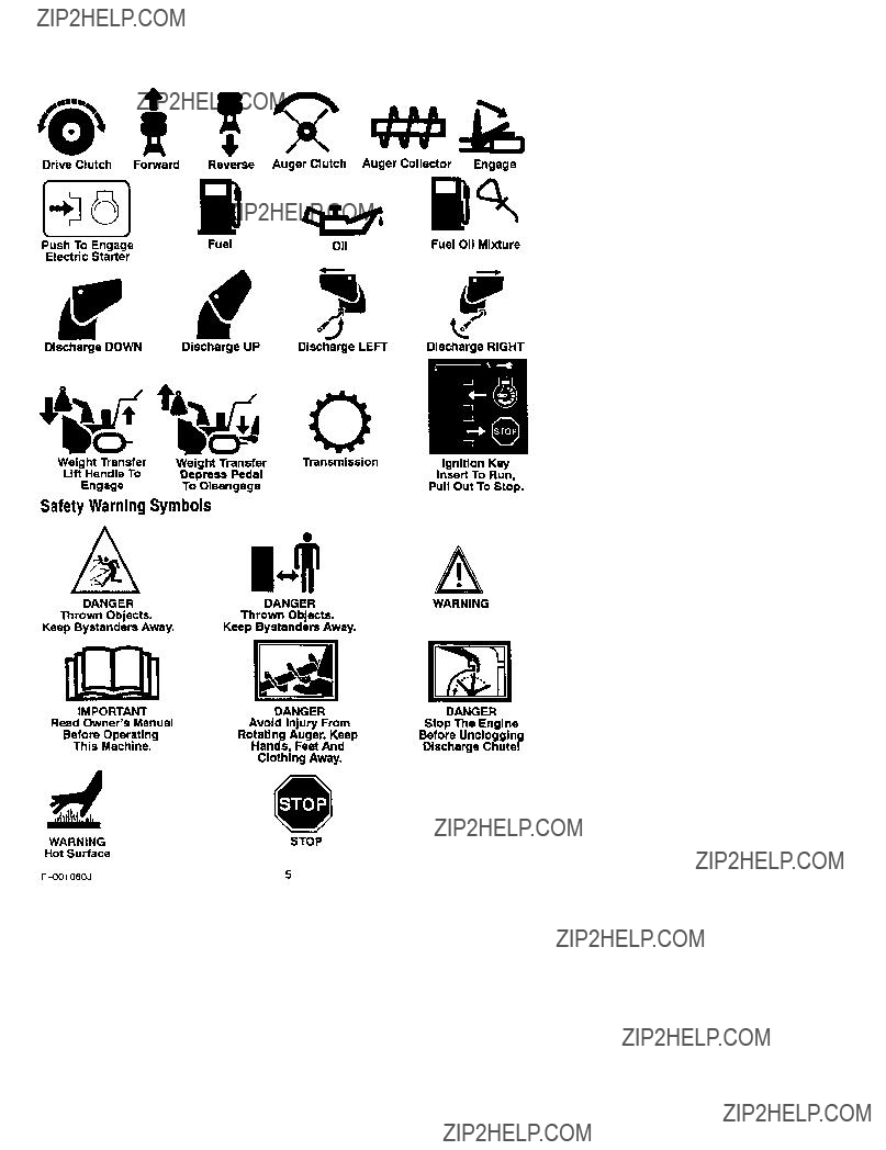
IMPORTANT: Many of the following symbols are located on your unit or on literature sup- plied with the product. Before you operate the unit, learn and understand the purpose for

each symbol.

Control And Operating Symbols

DriveClutch Forward ReverseAugerClutchAugerCollector Engage

PushToEngage FuelO]1 FuelOIIMixture

ElectricStarter

f

Discharge DOWN Discharge UP Discharge LEFT Discharge RIGHT

Safety Warning Symbols

Contents of Parts Bag (actual size)

1 - Owner's Manual (not shown)

1 - Packet of Fuel Stabilizer (not shown)

1 - Warranty Card (not shown)

2 - Parts bags (not shown)

*Non-Assembly Parts, found in toolbox located on belt cover

1- Screw, 3/8-16 x 2 in

1-Split Lockwasher

1- Nut, 3/8 In.

??

1-Flatwasher

3/8 In.

C z'e'l

Parts packed separately in carton (not shown full size)

2- Ignition Keys

(Attached to engine in plastic bag)

_lh safetyARNING:glassesAlwaysoreyewearshields while assembling snow

thrower.

TOOLS REQUIRED FOR

ASSEMBLY

1 - Knife to cut carton t - 1/2 inch wrenches

(or adjustable wrenches) 1 - 9/16 inch wrenches

(or adjustable wrenches) 1 - 3/4 inch wrenches

(or adjustable wrenches)

1 - Pliers (to spread cotter pin)

1 - Screwdriver

t - Measuring tape or ruler

Figure 1 shows the snow thrower in the shipping position.

Figure 1

Figure 2 shows the snow thrower com- pletely assembled,

References to the right or left hand side of the snow thrower are from the view-

point of the operator's position behind the unit.

AugerTraction

Lever

Cable

Chute

Shifter

Lever

Chute

Deflector

Figure 2

TO REMOVE SNOW THROWER

FROM CARTON

t.Locate all parts packed separately and remove from the carton.

NOTE: Place fuel stabilizer in a safe place until needed for storage.

2.Remove top pallet from carton.

3.Cut and discard the plastic ties se- curing the chute rod to the upper

pallet and place aside. Discard pal- let.

4, Cut down all four corners of the car- ton and lay the panels flat.

5.Cutthe bands holding the snow thrower to the lower pallet.

6.Remove snow thrower from lower pallet.

7.Remove the packing material from the handle assembly and all protec- tive material from unit and discard,

8.Cut ties securing the clutch control cables to the lower handle.

TO ASSEMBLE THE HANDLEAND

CRANK ASSEMBLY

t.Loosen, but do not remove, the screws, flatwashers, Iockwashers, and hex nuts in the upper holes of the lower handle. See Figure 3.

Right Hand Side

Of L

3/8" Hex

Loosen,Nut but do not*,,

remove

3/8" Flat-

Hex Nut,

3/8 x 2" Screw

3/8"

Figure 3

NOTE: Make sure the cables are not caught between the upper and lower

handle.

2.Raise the upper handle into operat-

ing position. Upper handle should be to the outside of the lower han-

die.

NOTE: Ifthe cables have become dis- connected form the clutch levers, rein- stall the cables as shown in Figure 4.

Clutch L_

Cont;cZ"IFitly, J

Cable _(_/

Figure 4

3.Install hardware supplied in the

parts bag (screw, flatwasher, Iock-

F-O01060J

washer, and hex nut) into bottom hole on right hand side of handles.

DO NOT tighten until all bolts are in place.

4.Locate crank assembly removed earlier and remove the nylon lock- nut and flatwasher from the eye bolt assembly. See Figure 5.

Left Hand Side Of

Upper Handle

3/8" Nylon

, Locknut

3/8"

3/8" Flatwasher

Figure 5

5.Reinstall flatwasher and adaptor.

Install eye bolt through lower hole on the left hand side of the handle.

6.Install the 3/8" flatwasher and the 3/8" nylon Iocknut loosely on the eye bolt.

7.Carefully remove cotter pin, clevis pin and universal joint pin from yoke end of crank rod assembly. See Figure 6.

8.Place universal joint into end of worm gear lining up Large holes. In- sert universal joint pin (ensure opening in pin Is In line with

small openings In universal joint).

9.Place yoke end of crank rod around universal Joint, lining up openings. Insert clevis pin through assembly and secure with cotter pin. Spread ends of cotter pin to lock in place.

10.Tighten nut on eye bolt. Make sure eye bolt is properly aligned and the crank can freely rotate.

11.Tighten all handle bolts.

8

CotterPin

Clevis Pin

Crank Rod

Figure 6

ASSEMBLE SNOW CHUTE

1.Remove back carriage bolt. See Figure 7.

2.Tilt chute back into operating posi- tion. See Figure 8.

3.Replace carriage bolt from inside of chute.

4.Replace fiat washer and nylon lock- nut on outside of flange.

5.Tighten carriage bolt securely.

NOTE: Check all carriage bolts in flange for tightness. DO NOT over- tighten.

Shipping Position

\

F-OOIO60J

Chutein Operating __

Position

Figure 8

NOTE: If the cables have become dis- connected, reinstall springs as shown in

Figure 9.

Auger Drive I

TractionDrive Spring(Short ,_

Spring(Long)_

CONNECT REMOTE CHUTE

1.Push remote chute control lever into "Chute Deflector Up" position.

2.Feed "Z" fitting through hole in re- mote chute bracket. See.

3.Snap remote chute control cable into remote chute bracket. See.

4.Connect "Z" fitting into remote chute control bracket. See.

5.Push remote chute control lever into "Chute Deflector Down" position.

6.Cut tie strap on chute deflector. See Figure.

SPEED SELECT LEVER

1.Cut plastic tie securing speed select lever assembly to the shifter brack- et. See Figure 10.

2.Remove Iocknut, washer, spring, and the bolt. See Figure 12.

3. Positionspeedselectorlever as-

sembly as shown in Figure 11.

4.Reinstall bolt, spring, washer and Iocknut See Figure 12.

5.Tighten Iocknut until 1/8 to 3/16 inch of the bolt threads protrude pas the

Iocknut.

6.Thread the 3/8-16" hex jam nut onto the lever until the nut reaches the end of the thread. See

Figure 12.

7.Thread the plastic knob as far as possible and ensure that the knob points forward.

8.Tighten the 3/8-16" hexjam nut against the knob securely.

9.Move shifter through all speeds to ensure proper tension of the spring. If shifter lever sticks in any of the

notches, loosen Iocknut 1/2 turn at a time until shifter lever moves more

freely.

10.If adjustment of speed of snow blower is needed, refer to "Friction

Wheel Adjustment" in the ADJUST- MENT/REPAIR section.

Shifter

Bracket

Plastic

Tie

Figure 10

Control

Panel

Figure 11

f!_.'x =1*]_I=]Ik'4

3/jSa-16 Hex

m Nut

1.Thread the 3/8-16" hex jam nut onto the lever until the nut reaches the end of the thread. See

Figure 13.

2, Thread the plastic knob as far as possible and ensure that the knob

points forward.

HOW TO SET THE SKID HEIGHT

Your snow thrower is equipped with height adjust skids on the outside of the auger housing. To adjust the skid height for different conditions, see To Adjust Skid Height paragraph in the Service And Adjustment section.

_" CHECKLIST

Before you operate your new snow thrower, to ensure that you receive the best performance and satisfaction from this quality product, please review the following checklist:

P" All assembly instructions have been

3."Rghten the 3/8-16" hex jam nut against the knob securely.

Remote Chute

Control Knob

Figure 13

HEADLIGHT

The headlight on your snow thrower is positioned down for packaging pur- poses. Rotate upward for operating position.

completed.

P" The discharge chute rotates freely. _" No remaining loose parts in carton.

While learning how to use your snow thrower, pay extra attention to the fol-

lowing important items:

_" Engine oil is at proper level.

._" Make sure gas tank is filled properly with clean, fresh, unleaded gasoline.

P" Become familiar with all controls- their location and function. Operate controls before starting engine.

bPj=l--Iri_l[i]_]

KNOW YOUR SNOW THROWER

READ THIS OWNER'S MANUAL AND SAFETY RULES BEFORE OPERATING YOUR SNOW THROWER. Compare the illustrations with your SNOW THROWER

to familiarize yourseff with the location of various controls and adjustments. Save this manual for future reference.

Chute Deflector

Discharge

Chok_

ControlRecoil

Throttle Starter

Control Handle

Figure 14

Auger Drive Lever - Starts and stops the auger and impeller (snow gathering and throwing)

Traction Drive Lever - Propels the snow thrower forward and in reverse.

Speed Shifter Lever - Selects the speed of the snow thrower (6 speeds for- ward and 2 speeds reverse).

Crank Assembly - Changesthe direction

of snow throwingthroughthe discharge chute.

Chute Deflector - Changes the distance

the snow is thrown.

Discharge Chute - Changes the height anddirectionthe snowis thrown.

Height Adjust Skid - Adjusts the ground clearance of the auger housing.

Ignition Key - Must be inserted to start the engine.

Recoil Starter Handle - Starts the en- gine manually.

F-OO1060J

Choke Control - Used to start a cold

engine.

Primer Button - Injectsfuel directly into the carburetor manifold for fast starts in

cold weather.

Remote Chute Control Lever - Push

forward to discharge snow high and far.

Pull remote lever back to discharge snow down.

Throttle Control - Controls the engine speed.

Electric Start Button - (If so equipped)

Usedto startthe engineusingthe 120V Edec- tnc starter.

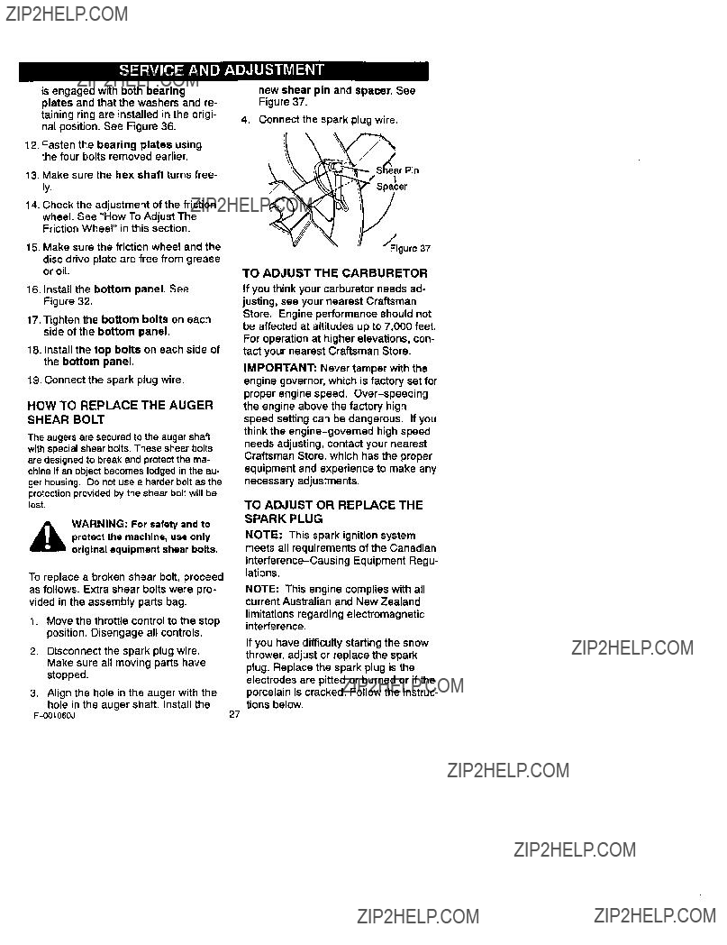
Shear Pin -Shear pins are designed to break (to protect the machine) if an ob-

iect becomes lodged in the auger hous- Ing.

Toolbox -spare shear pins and spacers

are located in toolbox,

12

The operation of any snow thrower can result in foreign objects being thrown into the eyes, which can result in se- vere eye damage. Always wear safety

glasses or eye shields while operating the snow thrower.

We recommend standard safety

glasses or a wide vision safety mask for over your glasses.

Manual before operating i_ WARNING: Read Owner's

machine. Never direct dis- charge toward bystanders stop the engine before unclogging discharge chute or auger housing and before leaving the machine,

TO STOP YOUR

SNOW THROWER

1.To stop throwing snow, release the auger drive lever. See Figure 14.

2.To stop the wheels, release the traction drive lever,

3.To stop the engine, push the

throttle control lever to off and pull out the ignition key.

TO CONTROL SNOW DISCHARGE 1, Turn the chute control rod to set the

direction of the snow throwing.

2.Loosen the wing knob on the chute deflector and move the deflector to set the distance. Move the deflector (Up) for more distance, (Down) for less distance. Then tighten the wing knob (See Figure 15).

Figure 15

HOW TO MOVE FORWARD AND

BACKWARD

1.To shift, release the traction drive lever (left hand) and move the speed shifter lever to the speed you desire. Ground speed is deter-

mined by snow conditions. Select

F-O010S0J

the speed you desire by moving the

speed shifter lever left into the ap- propriate notches on the shift lever plate:

Speeds 1,2 - Wet, Heavy

Speed 3 - Light

Speed 4 - Very Light

Speed 5,6 - Transport only

2.Engage the traction drive lever (left hand). As the snow thrower starts to move, maintain a firm hold on the handles, and guide the snow throw- er along the clearing path. Do not attempt to push the snow thrower.

3.To move the snow thrower back-

ward, move the speed shifter lever right into first or second reverse and engage the traction drive lever (left hand).

IMPORTANT: Do not move the speed shifter lever while the traction lever is down.

TO THROW SNOW

1.Push down the auger driver lever (right hand).

2.Release to stop throwing snow.

TO USE WHEEL LOCKOUT PIN

1, The left hand wheel is secured to the axle with a klick pin. This unit was shipped with this klick pin in the locked position (through wheel hole). See Figure 16,

Klick Pin

Locked

"__osition 2-Wheel Drive

Figure 16

2.For ease of maneuverability in light snow conditions, disconnect the

kllek pin from the wheel locked position and push into the single wheel drive position (unlocked axle hole only). See Figure 17.

13

ickPin

Unlocked

sition

NOTE: Make sure that the klick pin is in the single wheel drive position of the axle only and not through the locked position.

BEFORE STARTING THE ENGINE

1.Before you service or start the en- gine, familiarize yourself with the snow thrower. Be sure you under- stand the function and location of all controls.

2.Check the tension of clutch cable before starting the engine. See To Adjust The Control Cable para- graph in the Service & Adjust- ments section of this manual.

3.Be sure that all fasteners are tight.

4.Make sure the height adjust skids are properly adjusted. See To Ad- just Skid Height paragraph in the Service & Adjustments section of this manual.

5.Checktire pressure (14-17

pounds). Do not exceed maximum amount of pressure.

CHECK THE OIL"

NOTE: The engine was shipped from the factory filled with oil. Check the lev- el of the oil. Add oil as needed.

1.Make sure the unit is level.

NOTE: Do not check the level of the oil while the engine runs.

2.Remove the oil fill cap/dipstick.

Check the oil.

3.if necessary, add oil until the oil reaches the FULL mark on the oil fill

cap/dipstick (see Figure 18). Do not add too much oil.

F-001060J

OII Fill C_t_p/Dipstick

;.._:_/ NOTE: Oil level

_'),y must be between full and Add mark

Figure18

4.Tighten the fill cap/dipstick securely each time you check the oil level,

NOTE: For extreme cold operating conditions of 0??F and below, use a par- tial synthetic 0W30 motor oil for easier starting.

NOTE: S.A.E. 5W30 motor oil may be used to make starting easier in areas where temperature is consistently 20??F. or lower.

FILL GAS:

NOTICE: ENGINES WHICH ARE

CERTIFIED TO COMPLY WITH CAL-

IFORNIA AND US EPA EMISSION

REGULATIONS FOR ULGE ENGINES: Are certified to operate on regular un- leaded gasoline. Include the following emission control system(s): EM, TWC (If so equipped). Include any user ad- justable features-therefore no other ad- justments are needed.

dicates that alcohol blended i_ WARNING: Experiences In-

fuels (called gasohol or those using ethanol or methanol) can attract moisture which leads to separation and formation of acids during storage. Acidic gas can dam- age the fuel system of an engine while In storage.

NOTE: To avoid engine problems, the fuel system must be emptied before storage for 30 days or longer. Start the engine and let it run until the fuel lines and carburetor are empty, Use the car- buretor bowl drain to empty residual gasoline from the float chamber. Use fresh fuel next season. See the Stor-

age section in this manual for additional information.

14

Never use engine or carburetor cleaner products in the fuel tank or permanent damage may occur.

1Fill the fuel tank only with a fresh, clean, unleaded regular, unleaded

premium, or reformulated automo- tive gasoline. DO NOT use leaded gasoline. Make sure that the con- tainer you pour the gasoline from is clean and free from rust or other for-

eign particles. Never use gasoline that may be stale from long periods of storage in the container.

mable. Always use caution _b ARNING: Gasoline is flam-

when handling or storing

gasoline.

Do not fill fuel tank while snow thrower is running, when It Is hot, or when snow thrower Is In an en- closed area.

Keep away from open flame or an electrical spark and do not smoke while filling the fuel tank.

Never fill the tank completely. Fill the tank to within 1/4"-1/2" from the top to provide space for expansion of fuel.

Always fill fuel tank outdoors and use a funnel or spout to prevent spilling.

Make sure to wipe up any spilled fuel before stating the engine. Store gasoline In a clean, approved container and keep the cap in place on the container.

TO STOP ENGINE

To stop engine, move the throttle con- trol lever to "STOP" position and re- move key. Keep the key in a safe place. The engine will not start without the key.

TO START ENGINE

(electric starter, if equipped)

Be sure that the engine has sufficient " oil. The snow thrower engine is equipped with a 120 volt A.C. electric starter and recoil starter. Before start-

F-001060J

inn the engine, be certain that you have read the following information.

equipped with a three-wlra ,_ WARNING: The starter Is

power cord and plug and Is designed to operate on 120 volt AC household current.It must be proper- ly grounded at all times to avoid the possibility of electrical shock which may be Injurious to operator. Follow all Instructions carefully as set forth In the "To Start Engine" section. De- termine that your house wiring Is a three-wire grounded system. Ask a licensed electrician If you are not sure. If your house wire system Is not a three-wire system, do not use this electric starter under any condi- tions. If your system is grounded and a thrae-hole receptacle is not available at the point your starter will normally be used, one should be installed by a licensed electrician. when connecting 120 volt AC "Power

Cord", always connect the cord to the Switch Box" on the engine first, then plug the other end into the three-hole grounded receptacle. When disconnecting "Power cord", always unplug the end In the three- hole grounded receptacle first.

COLD START

1.Be sure auger drive and traction drive levers are in the disengaged (RELEASED) position.

2.Move throttle controt to"FAST" posi- tion,

3.Remove the keys form the plastic bag. Insert one key into ignition

slot. Make sure it snaps into place. Do not turn key. Keep the second key in a safe place.

4.Rotate choke knob clockwise to the choke ON position.

5.Connect the power cord to the switch box on the engine.

6.Plug other end of power cord into a three-hole, grounded t 20 VOLT, AC receptacle. (See WARNING in this section).

15

7.Push the primer button while cov- ering the vent hole as follows: Re- move finger from primer button between primes.

Do not prime if temperature above

50 ?? F (10 ?? C).

Push two time if temperature is 50 ?? F (10 = C) to 15??F (-10 = C).

Push four times if temperature is below 15?? F (-10 ?? C).

8.Push down on the starter button until the engine starts. Do not crank for more than 10 seconds at a time.

This electric starter is thermally pro- tected. If overheated it will stop au- tomatically and can be restarted only when it has cooled to a safe temperature (a wait of about 5 to 10 minutes is required).

9.When the engine starts, release the starter button and move choke le-

ver to "1/2 choke" position. When engine runs smoothly, move choke lever to "No Choke" Position.

10.Disconnect power cord from recep- tacle, first, and then from switch box.

NOTE: Allow the engine to warm up for

several minutes before blowing snow in temperatures below 0??F.

11, Run engine at full throttle "FAST' when throwing snow.

WARM START

ff restarting a warm engine afier a short shutdown, leave choke at "OFF" and do

not push the primer button, If the en-

gine fails to start, follow the Cold Start instructions.

TO START ENGINE

(recoil starter)

Be sure that the engine has sufficient oil. The snow thrower engine is

equipped with a recoil starter. Before starting the engine, be certain that you have read the following information.

F-0010SOJ

COLD START

1, Be sure auger drive and traction drive levers are in the disengaged (RELEASED) position,

2.Move throttle control to"FAST' posi- tion.

3.Remove the keys form the plastic bag. Insert one key Into ignition slot. Make sure it snaps into place. Do not turn key. Keep the second key in a safe place.

4.Rotate choke knob clockwise to the choke ON position.

5.Push the primer button while cov- ering the vent hole as follows: Re- move finger from primer button between primes.

Do not prime if temperature above 50 ?? F (10?? (3).

Push two time if temperature is 50 ?? F (10 ?? C) to 15??F (-10 ?? C).

Push four times if temperature is below 15 ?? F (-10 ?? C).

6.Pull the starter handle rapidly. Do not allow the handle to snap back, but allow it to rewind slowly while keeping a firm hold on the starter handle.

7.As the engine warms up, move choke lever to "1/2 choke" position.

When engine runs smoothly, move choke lever to "No Choke" Posi-

tion.

NOTE: Allow the engine to warm up for several minutes before blowing snow in temperatures below OoF.

8.Run engine at full throttle "FAST' when throwing snow.

WARM START

If restarting a warm engine after a short shutdown, leave choke at "OFF" end do not push the primer button. Ifthe en-

gine fails to start, follow the Cold Start instructions.

FROZEN STARTER

If the starter is frozen and will not turn

engine:

1.Pull as much rope out of the starter as possible.

16

2.Release the starter handle and let it snap back against the starter.

If the engine still fails to start, repeat the

two previous steps until the engine starts. Then continue with the direc-

tions for cold start.

To help prevent possible freeze-up of recoil starter and engine controls, pro- ceed as follows after each snow remov- al job.

1.With the engine running, pull the starter rope hard with a continuous full arm stroke three or four times.

Pulling of starter rope will produce a loud clattering sound. This is not harmful to the engine or starter.

2.With the engine not running, wipe all snow and moisture from the carbu- retor cover in area of control levers.

Also move throttle control, choke control, and starter handle several times.

gine indoors or in enclosed, ,_ WARNING: Never run en-

poorly ventilated areas. En- gine exhaust contains CARBON

MONOXIDE, AN ODORLESS AND DEADLY GAS. Keep hands, feet, hair and loose clothing away from any moving parts on engine and snow thrower.

The temperature of muffler and

nearby areas may exceed 150??F.

Avoid these areas.

DO NOT allow children or young teenagers to operate or be near snow thrower while It Is operating.

to remove any Item that may _b ARNING: Do not attempt

become lodged in auger without taking the following precau- tions:

Release auger drive lever.

Move throttle lever to stop posi- tion.

Remove (do not turn) Ignition key.

Disconnect spark plug wire. Do not place your hands in the

auger or discharge chute. Use s pry bar.

SNOW THROWING TIPS

1.For maximum snow thrower efficien- cy in removing snow, adjust ground speed, NEVER the throttle. Go slower in deep, freezing or wet snow. Ifthe wheels slips, reduce forward speed. The engine is de- signed to deliver maximum perfor- mance at full throttle and should be run at this power setting at all times.

2.Most efficient snow throwing is ac- complished when the snow is re-

moved immediately after if falls.

3.For complete snow removal, slightly overlap each path previously taken.

4.The snow should be discharged down wind whenever possible.

5.For normal usage, set the skids so that the scraper bar is 1/8" above the skids. For extremely hard- packed snow surfaces, adjust the skids upward so that the scraper bar touches the ground.

6.On gravel or crushed rock surfaces, set the skids at 1-1/4" below the scraper bar. See To Adjust Skid Height paragraph in the Service & Adjustments section of this manu- al. Rocks and gravel must not be

picked up and thrown by the ma- chine.

7.After the snow throwing job has been completed, allow the engine to idle for a few minutes, which will melt snow and accumulated ice off the engine.

8.Clean the snow thrower thoroughly after each use.

9.Remove ice and snow accumulation and all debris from the entire snow thrower, and flush with water (if pos- sible) to remove all salt or other chemicals. Wipe snow thrower dry.

GENERAL RECOMMENDATIONS

The warranty on this snow thrower does not cover items that have been

subjected to operator abuse or negli- gence. To receive full value from the

warranty, the operator must maintain the snow thrower as instructed in this manual.

Some adjustments will need to be made periodically to properly maintain your snow thrower.

All adjustments in the Service and Ad- justments section of this manual should be checked at least once each season.

AFTER EACH USE

Check for any loose or damaged

If any parts are worn or damaged, replace immediately.

LUBRICATION CHART

Lubricate

Disc Drive

Plate Zerk

With a Hi

Tem

Moly

Grease.

Figure 19

PRODUCT SPECIFICATIONS

prevent rubber friction wheel con- tacting the drive disc plate.

6.To grease zerk, use a hand grease gun, lubricate with a Hi Temp EP Moly grease. Fill zerk only until grease becomes visible below bear-

ing assembly located under grease zerk. DO NOT over fill.

CAUTION: DO NOT allow grease to come in contract with the disc drive

plate or friction wheel or damage will result.

IMPORTANT: Remove coin and en- sure that a gap exists between friction wheel and disc drive plate.

NOTE: Clean all excess grease found on friction disc hub.

SNOW THROWER

Sprockets

Hex Shaft and Sprockets

AS REQUIRED

The following adjustment should be preformed more than once each sea- son.

I.Auger drivebeltshould be adjusted afterthefirst2 to 4 hoursof use, againabout mid-season and twice each season thereafter(See to Ad- justBelts paragraph in the Ser- vice and Adjustment section).

LUBRICATION-EVERY 25 HOURS

Lubricate Disc Drive Plate every twenty-five (25) hours and at the end of the season and/or before storage.

To Lubricate

1.Position speed selector lever in first gear,

2, Stand the snow thrower up on the auger housing end.

3.Remove the bottom panel,

4.Turn disc drive plate clockwise by hand until grease zerk is clearly visible at front center. See

Figure 20.

5, Place a coin or (a shim of equal thickness) between the rubber fric- tion wheel and disc drive plate to

F-OOIO60J

(Require No

Lubrication

Friction

Disc

Drive

Plate

Gap Between

Friction Wheel

and Disc Drive

/Plate

LUBRICATION-NOT REQUIRED

1, Hex Shaft and Sprockets - Hex shaft and sprockets require no lu- brication, All bearings and bushings are lifetime lubricated and require no maintenance. See Figure 20.

NOTE: Any greasing or oiling of the above components can cause contami- nation of the friction wheel. If the disc

19

driveplateorfrictionwheelcomein contactwithgreaseoroil damageto

the friction wheel will result.

Should grease or oil come in contact with the disc drive plate or friction wheel, be sure to clean the plate and wheel thorough[y,

NOTE: For storage, the hex shaft and sprockets should be wiped with 5W30 motor oil to prevent rusting.

2.Auger Gear Box - The auger gear box is lubricated at the factory and

should not require additional lubrica- tion. Iffor some reason the lubri-

cant should leak out, have auger gear case checked by a competent repairman.

ENGINE

LUBRICATION

Check the crankcase oil level before starting the engine and after each five

(5) hours of continuous use. See Figure 21. Add S.A.E. 5W30 motor oil as needed. Tighten fill cap/dipstick se-

curely each time you check the oil lev- el.

Oil Fill Cap/Di_,

Figure 21

Change the oil every twenty-five (25) hours or at least once a year if the

snow thrower is not used for twenty- five (25) hours.

F_OIO60J

TO CHANGE ENGINE OIL

1.Position the snow thrower so that the oil drain plug is at the lowest point on the engine.

2.Remove the oil drain plug and the oil fill cap/dipstick. Drain the oil into a suitable container.

NOTE: The oil will drain more freely when the engine is warm.

3.After draining all the oil, reinstall the oil drain plug securely.

4.Fill the engine crankcase with S.A.E. 5W30 motor oil, pouring slowly. DO NOT OVERFILL.

SPARK PLUG

Check the spark plug every twenty- five (25) hours. Replace the spark plug if the electrodes are pitted or burned or if the porcelain is cracked.

1.Make sure the spark plug is clean. Clean the spark plug by carefully scraping the electrodes (do not sand blast or use a wire brush),

2.Check the spark plug gap with a feeler gauge and reset gap to 0.30" if necessary. See Figure 22.

3.Before installing the spark plug, coat the threads lightly with oil for easy removal. Tighten the spark plug to a torque of 15 foot-pounds.

Feeler Gauge

0.030"

Spark Plug

Figure 22

20

[,._:l] _kVJ[e.=] r_1_I H A.!i]I[ll- v'jil_l_I i

,_hl= WARNING: Always discon-

nect the spark plug wire and place it where It cannot

make contact with spark plug to pre- vent accidental starting when mak- ing any adjustments or repairs.

TO ADJUST SKID HEIGHT

This snow thrower is equipped with two height adjustment skids, located on the outside of the auger housing. See Figure 23.

These skids elevate the front of the snow thrower.

Nuts

O

raise the adjustable skids. Tighten the mounting nuts. See Figure 23.

NOTE: For rocky or uneven surfaces, raise the front of the snow thrower by moving the skids down.

maintain proper ground _1 WARNING: Be certain to

clearance for your particular area to be cleared. Objects such as gravel, rocks or other debris, If

struck by the Impeller, may be thrown with sufficient force to cause

personal injury, property damage or damage to the snow thrower.

TO ADJUST SCRAPER BAR

After considerable use, the metal scrap- er bar will have a definite wear pattern. The scraper bar in conjunction with the skids should always be adjusted to al- low 1/8" between the scraper bar and the sidewalk or area to be cleaned,

Figure 23

For normal hard surfaces, such as a

paved driveway or walk, adjust the skids as follows.

1.Position the snow thrower on a level surface.

2.Make sure both tires are equally in- flated. Proper tire pressure is 14 to 17 PSI. See side of tire for maxi- mum inflation. Do not exceed side- wall maximum pressure on tire.

3.Place the extra shear bolts supplied (found in parts bag) under each end of the scraper bar next to the adjustable skids.

4.Loosen the mounting nuts that hold the adjustable skids. To bring the front of the snow thrower down,

1.Position the snowthrower on a level surface.

2.Make sure both tires are equally in- flated. Proper tire pressure is 14to 17 PSI. See side of tire for maxi- mum inflation. Do not exceed side- wall maximum pressure on tire.

3.Loosen the carriage bolts and nuts securing the scraper bar to the au- ger housing,

4.Adjust the scraper bar to the proper position.

5.Tighten the carriage bolts and nuts, making sure that the scraper bar is parallel with the working surface.

6.For extended operation, the scraper bar may be reversed. If the scraper bar must be replaced due to wear, remove the carriage bolts and nuts and install a new scraper bar.

HOW TO CHECK AND ADJUST

THECABLES

The cables are adjusted at the factory

and no adjustment should be neces- sary. If the cables have become stretched or are sagging adjustment wilt be necessary.

To check for correct adjustment,discon- nect the Z-fitting at the drive lever, move the drive lever to the full forward

position, just contacting the plastic bumper. The control cables are cor- rectly adjusted when the center of the "Z" fitting is between the center and top of the hole in the drive lever and there in no droop in the cable. See

Figure 24.

Drive Lever

_t_stic

Bumper Figure 2,$

1.Remove gas from gas tank. Stand snow thrower on end.

2.Disconnect the "Z" fitting from drive lever.

3.Pull spring cover up to expose spring, Push the cable through the spring to expose the threaded por- tion of the cable. See Figure 25.

4.Hold the square end of the threaded portion with pliers and ad- just the Iocknut in or out until the excess slack is removed.

Square End,_

Locknut

Spring _

Figure25

5.Pull the cable back through the

spring and connect the cable. Do the same for the other drive lever

cable, if needed.

NOTE: Whenever the traction drive or auger belts are adjusted or replaced, the cables will need to be adjusted.

TO ADJUST BELTS

Belts stretch during normal use, If you need to adjust the belts due to wear or stretch, proceed as follows:

How To Adjust The Auger Drive Belt If your snow thrower will not discharge snow, check the control cable adjust- ment. If it is correct, then check the condition of the auger drive belt. It may be loose or damaged. If it is damaged, replace it. See To Replace Belts para- graph in this section. If the auger drive belt is loose, adjust as follows:

1.Disconnect the spark plug wire.

2.Remove the belt cover. See

Figure 26.

Belt Cover

/

Flatwasher

Self Tapping Screw Figure 26

Loosen this nut

Figure 27

3.Loosen the nut on the Idler pulley and move the pulley toward the belt about 1/8", See Figure 27.

4, "lighten the nut.

5.Press the auger drive lever. Check the tension on the belt (opposite au- ger idler pulley). The belt should deflect about 1/2" with moderate pressure (See Figure 28).

Figure 28

NOTE: If the adjustment is not correct, repeat the adjustment.

6.Replace the belt cover,

7.Check the clutch control cable ad- justment.

8.Reconnect the spark plug wire.

Traction Drive Belt

The traction drive belt has constant spring pressure and does not require adjustment. Replace the traction drive belt if it is slipping, See To Replace Belts paragraph in this section.

F-O0106OJ

TO REPLACE BELTS

The drive belts on this snow thrower

are of special construction and should be replaced with original equipment belts available from your nearest

Craftsman Store, A distributor's list is supplied in the parts manual.

You _'illneed the assistance of a sec- ond person while replacing the belts.

How To Remove The Auger Drive Belt If the auger drive belt is damaged, the snow thrower will not discharge snow, Replace the damaged belt as follows, 1, Remove the gas from the gas tank.

Stand the snow thrower up on the front end of the auger housing.

outdoors, away from fire or

,_ WARNING: Drain the gasoline flame.

2.Disconnect the spark plug wire.

3.Remove the screw from the belt cover. Remove the belt cover. See Figure 26.

4, Remove the bolts on each side of the motor mount frame. See Figure 29.

5.Loosen the bolts on each side of the motor mount frame, The au- ger housing and the motor mount

frame will separate, hinged by the bolts.

Remove top bolt (each

(Each Side)Figure 29

6, Loosen the belt guide. Pull the belt guide away from the auger drive pulley, See Figure 27.

7.Loosen the nut on the idler pulley. Pull the Idler pulley away from the auger drive belt.

23

8.Removetheoldaugerdrivebelt. Replacetheaugerdrivebeltwith

anoriginalfactoryreplacementbelt

available from an authorized service center.

9.Install the new auger drive belt onto the auger drive pulley and onto the drive pulley.

10.Adjust the auger drive belt. See "How To Adjust The Auger Drive Belt" in the Service And Adjustment section.

11.Adjust the belt guide. See "How To Adjust The Belt Guide" in the Ser- vice And Adjustment section.

12.Install the bolts on each side of the motor mount frame. See

Figure 29.

13.Tighten the bolts on each side of the motor mount frame.

14.Install the belt cover. Tighten the screw. See Figure 26.

15.Check the adjustment of the cables. See "How To Check And Adjust The

Cables" in the Service And Adjust- ment section.

16.Connect the spark plug wire.

How To Remove the Traction Drive

Belt

If the snow thrower will not move for- ward, check the traction drive belt for wear or damage. If the traction drive belt is worn or damaged, replace the belt as follows.

1.Remove the gas from the gas tank. Stand the snow thrower up on the front end of the auger housing.

outdoors, away from fire or _hlL ARNING: Drain the gasoline

flame.

2.Disconnect the spark plug wire.

3.Remove the auger drive belt. See "How To Remove The Auger Drive

Belt" in the Maintenance section.

F-001060J

4.Pull the traction drive idler pulley away from the traction drive belt.

See Figure 30.

TractionDrive Belt

5.Remove the old traction drive belt from the traction drive pulley and from the engine pulley. Replace the traction drive belt with an original

factory replacement belt available from an authorized service center.

6.Install the new traction drive belt onto the traction drive pulley and onto the engine pulley.

7.Make sure the traction drive idler

pulley is properly aligned with the traction drive belt.

8.Install and adjust the auger drive belt. See "How To Remove The Au-

ger Drive Belt" in the Service And Adjustment section.

9.Adjust the belt guide. See "How To Adjust The Belt Guide" in the Ser- vice And Adjustment section.

10.Install the bolts on each side of the motor mount frame. See Figure 29.

11.Tighten the bolts on each side of the motor mount frame.

12.Install the belt cover. Tighten screw. See Figure 26.

13.Check the adjustment of the cables. See "How To Check And Adjust The Cables" in the Service And Adjust- ment section.

14.Connect the spark plug wire.

24

HOWTOADJUSTTHEBELTGUIDE

1.Disconnectsparkplugwire.

2.RemovethescrewRemovethe. beltcoverSeeFigure26. .

3.Engagetheaugerdrivelever.

4.Measurethedistancebetweenthe beltguideandaugerdrivebelt. Thecorrectdistanceis1/8inch

(3.175mm). See Figure 31.

Belt Guide

Auger _'_??_ 1/8 Inch

idler _ f \\ (3.175 mm)

Pulley -"_--_ \\

Engaged_

Figure 31

5.If an adjustment is necessary, loos- en the mounting bolt for the belt guide. Move the belt guide to the correct position. Tighten the mounting bolt for the belt guide.

6.Install the belt cover. Tighten the screw. See Figure 26.

7.Connect the spark plug wire.

HOW TO ADJUST OR REPLACE

THE FRICTION WHEEL

How To Check The Friction Wheel

If the snow thrower will not move for- ward, check the traction drive belt, the

traction drive cable or the friction wheel. If the friction wheel is worn or damaged, it must be replaced. See "How To Re-

place the Friction Wheel" in this section. If the friction wheel is not worn or dam-

aged, check as follows.

outdoors, away from fire or

_lb ARNING: Drain the gasoline flame.

2.Disconnect the spark plug wire.

3.Remove the bolts on each side of the bottom panel. See Figure 32.

4.Loosen the bolts on each side of the bottom panel.

5.Remove the bottom panel.

Panel

6.Position the shift speed lever in the first forward gear.

7.Note the position of the friction

wheel on the disc drive plate (See Figure 33). In the correct position, the right outer side of the disc drive plate must be three inches

(7.62cm.) from the center of the friction wheel, if the friction wheel

is not in the correct position, adjust as follows.

/_Frillwl=ti_n..... _ "_+

O,ve-m" V-ll "

Plate .gt._""'-

1.Remove the gas from the gas tank. Stand the snow thrower up on the

How To Adjust The Friction Wheel

1, Remove washer and cotter pin con- necting trunnion nut to speed rod.

See Figure 34.

/Speed Control Rod

/Trunnion

6.Remove the three fasteners that hold the friction wheel to the hub.

See Figure 35.

Hub

Bolt

Figure 34

2.Twist trunnion nut up or down on shift rod to obtain the correct friction

wheel position.

3.Put end of trunnion nut through hole in speed control rod and reattach washer and cotter pin.

4.Tighten the bolts on each side of the bottom panel.

???HexNut Shaft

Figure35

7, Remove the four bolts that hold the bearing plates on each side of the hex shaft. See Figure 36.

NOTE: Take special note of the position of the washers and retain- ing ring on the hex shaft and the sprocket assembly.

FrictionV_'hl_eelHex Shaft"_

5.Install the bolts on each side of the bottom panel.

How To Replace The Friction Wheel

If the friction wheel is worn or damaged, the snow thrower will not move forward. The friction wheel must be replaced as

follows,

1, Remove the gas from the gas tank. Stand the snow thrower up on the front end of the auger housing,

4_5 WARNING: Drain the gasoline

outdoors, away from fire or flame.

2.Disconnect the spark plug wire.

3.Remove the top bolts on each side of the bottom panel. See

Figure 32.

4.Loosen the bottom bolts on each side of the bottom panel.

5.Remove the bottom panel.

Plate

Figure 36

8.Remove the bearing plate from the right side. Do not remove the bex shaft. Leave the hex shaft in posi- tion. Carefully raise hex shaft just enough to allow the friction wheel to be removed.

9.Remove the friction wheel from the

hub, Slip the friction wheel toward the right off the hex shaft. See Figure 35.

t0. Assemble the new friction wheel onto hub with the fasteners re- moved earlier.

11.Install the bearing plate onto the right side. Make sure the hex shaft

isengagedwithbothbearing platesandthatthewashersandre- tainingringareinstalledtheorigi- nalpositionSeeFigure36. .

12,Fastenthebearingplatesusing

thefourboltsremovedearlier.

13.Make sure the hex shaft turns free- ly.

t 4. Check the adjustment of the friction

wheel. See "How To Adjust The

Friction Wheel" in this section.

15.Make sure the friction wheel and the

disc drive plate are free from grease or oil.

16.Install the bottom panel. See Figure 32.

17.Tighten the bottom bolts on each side of the bottom panel.

18.Install the top bolts on each side of the bottom panel.

19.Connect the spark plug wire,

HOWTO REPLACE THE AUGER

SHEAR BOLT

The augers are secured to the auger shaft with special shear bolts. These shear bolts are designed to break and protect the ma- chine if an object becomes lodged in the au- ger housing. Do not use e harder bolt as the protection provided by the shear bolt will be lost.

,_ WARNING: For safety and to protect the machine, use only original equipment shear bolts.

To replace a broken shear bolt, proceed

as follows. Extra shear bolts were pro-

vided in the assembly parts bag.

1.Move the throttlecontrolto the stop position.Disengage all controls,

2.Disconnect the spark plug wire. Make sure aH moving parts have stopped.

3.Align the hole in the auger with the

hole in the auger shaft. Install the

F-0010SOJ

new shear pin and spacer. See

Figure 37.

4.Connect the spark plug wire.

/S!elar Pin

ar

_Figure 37

TO ADJUST THE CARBURETOR

If you think your carburetor needs ad- justing, see your nearest Craftsman

Store. Engine performance should not be affected at altitudes up to 7,000 feet.

For operation at higher elevations, con- tact your nearest Craftsman Store.

IMPORTANT: Never tamper with the engine governor, which is factory set for proper engine speed. Over-speeding

the engine above the factory high speed setting can be dangerous. If you think the engine-governed high speed needs adjusting, contact your nearest Craftsman Store, which has the proper equipment and experience to make any necessary adjustments.

TO ADJUST OR REPLACE THE

SPARK PLUG

NOTE: This spark ignition system

meets all requirements of the Canadian Interference-Causing Equipment Regu- lations.

NOTE: This engine complies with all current Australian and New Zealand

limitations regarding electromagnetic interference.

If you have difficulty starting the snow thrower, adjust or replace the spark plug. Replace the spark plug is the electrodes are pitted or burned or if the porcelain is cracked. Follow the instruc- tions below.

27

TOadjust:

1, Clean spark plug by carefully scraping the electrodes (Do not sand blast or use a wire brush).

2.Be sure spark plug is clean and free of foreign material. Check elec- trodes gap with a wire feeler gauge and reset gap to 0.030" if neces- sary. See Figure 38.

To Replace:

1.If you need a new spark plug, use only the proper replacement spark plug.

2.Set the gap to 0.030 inches.

3.Before installing the spark plug, lightly coat the spark plug threads

with oil or grease to insure easy re- moval.

4.Firmly tighten the spark plug in the engine.

5.If a torque wrench is available, torque the plug to 18 to 23 foot pounds.

Feeler Gauge

Spark Plug

Figure 38

snow thrower Indoors or In _ARNING: Never store your

an enclosed, poorly venti- lated area. If gasoline remains in the tank, fumes may reach an open flame, spark or pilot light from a fur- nace, water heater, clothes dryer, cigarette, etc.

NOTE: To prevent engine damage (if snow thrower is not used for more than 30 days) follow the steps below.

SNOW THROWER

1.Thoroughly clean the snow thrower.

2.Lubricate all lubrication points. See the Maintenance section.

3.Be sure that all nuts, bolts and screws are securely fastened. In- spect all visible moving parts for damage, breakage and wear. Re- place if necessary.

4.Touch up all rusted or chipped paint surfaces; sand lightly before paint- ing.

5.Cover the bare metal parts of the blower housing auger and the im- peller with rust preventative, such as a spray lubricant.

NOTE: A yearly checkup or tune-up by a Sears service center is a good way of

ensuring that your snow thrower will

provide maximum performance for the next season.

ENGINE

,_ WARNING: Drain the gaso-

line outdoors, away from fire or flame.

Gasoline must be removed or treated to prevent gum deposits from forming in the fuel tank, filter, hose, and carburetor during storage. Also, during storage al-

cohol blended gasoline that uses etha- nol or methanol (sometimes called gasohol) attracts water. It acts on the gasoline to form acids which damage the engine.

F-OOIO60J

1.To remove gasoline, run the engine until the fuel tank is empty and the engine stops.

2.If you do not remove the gasoline, use fuel stabilizer supplied with unit

or purchase Craftsman Fuel Stabi- lizer No. 3550. Add fuel stabilizer to

any gasoline left in the tank to mini- mize gum deposits and acids. If the fuel tank is almost empty, mix stabi- lizer with fresh gasoline in a sepa- rate container and add some to the fuel tank.

3.Always follow the instruction on the stabilizer container. After the stabi- lizer is added to the fuel tank, run the engine at least ten minutes to allow the mixture to reach the car- buretor.

4.Change the engine oil.

5.Lubricate the piston/cylinder area. First, remove the spark plug and squirt a few drops of clean engine oil into the spark plug hole. Next, cover the spark plug hole with a rag to absorb oil spray. Then, pull two or three times on the recoil starter rope to rotate the engine. FinaLly, install the spark plug and attach the spark plug wire.

OTHER

t.If possible, store your snow thrower indoors and cover it to give protec- tion from dust and dirt.

2.If the machine must be stored out-

doors, block up the snow thrower to be sure the entire machine is off the

ground,

3.Cover the snow thrower with a suit- able protective cover that does not retain moisture. Do not use plastic.

IMPORTANT: Never cover snow

thrower while engine and exhaust areas are still warm.

29

TROUBLE

Difficultstarting

Engine runs erratic

Engine stalls

Engine runs erratic; Loss of power

Excessive vibration

Unit fails to propel Itself

Unit falls to discharge snow

F-OOIOSOJ

,CAUSE

Defective spark plug.

Water or dirt in fual system.

Blocked fuel line, empty gas tank, or stale gasoline

Unit running on CHOKE.

Water or dirt in fuel system.

Loose parts: damaged impeller

)rive belt loose or damaged.

Incorrect adjustment of

traction drive cable

i Worn or damaged friction wheel.

Auger drive belt loose or damaged.

Auger control cable not adjusted correctly.

Shear bolt broken

Discharge chute clogged.

Foreign objectlodgedin auger

30

CORRECTION

Replace spark plug.

I Use carburetor bowl drain to flush and refill with fresh fuel.

Clean fuel line; check fuel

supply; add fresh gasoline

Set choke lever to RUN _osLtion.

Use carburetor bowl drain to flush and refill with fresh fuel.

Stop engine immediately and disconnect spark plug wire.

Tighten all bolts and make all necessary repairs. If vibration continues, have the

unit serviced by a Craftsman service repairman.

Replace drive belt.

Adjust traction drive cable.

Replace friction wheel,

Adjust auger drive belt; replace if damaged.

Adjust auger control cable.

Replace shear bolt

Stop engine immediately and disconnect spark plug wire. Clean discharge chute and inside of auger housing,

Stop engine immediately and

disconnect spark plug wire. Remove object from auger.