CRAFTSMAN
9 Horse Power
26"
Snow Thrower
Model No.
CAUTION: Before using this product, read this manual and follow all Safety Rules and Operating Instructions.
Sears, Roebuck And Co., Hoffman Estates, IL 60179, U.S.A.
CRAFTSMAN
9 Horse Power
26"
Snow Thrower
Model No.
CAUTION: Before using this product, read this manual and follow all Safety Rules and Operating Instructions.
Sears, Roebuck And Co., Hoffman Estates, IL 60179, U.S.A.
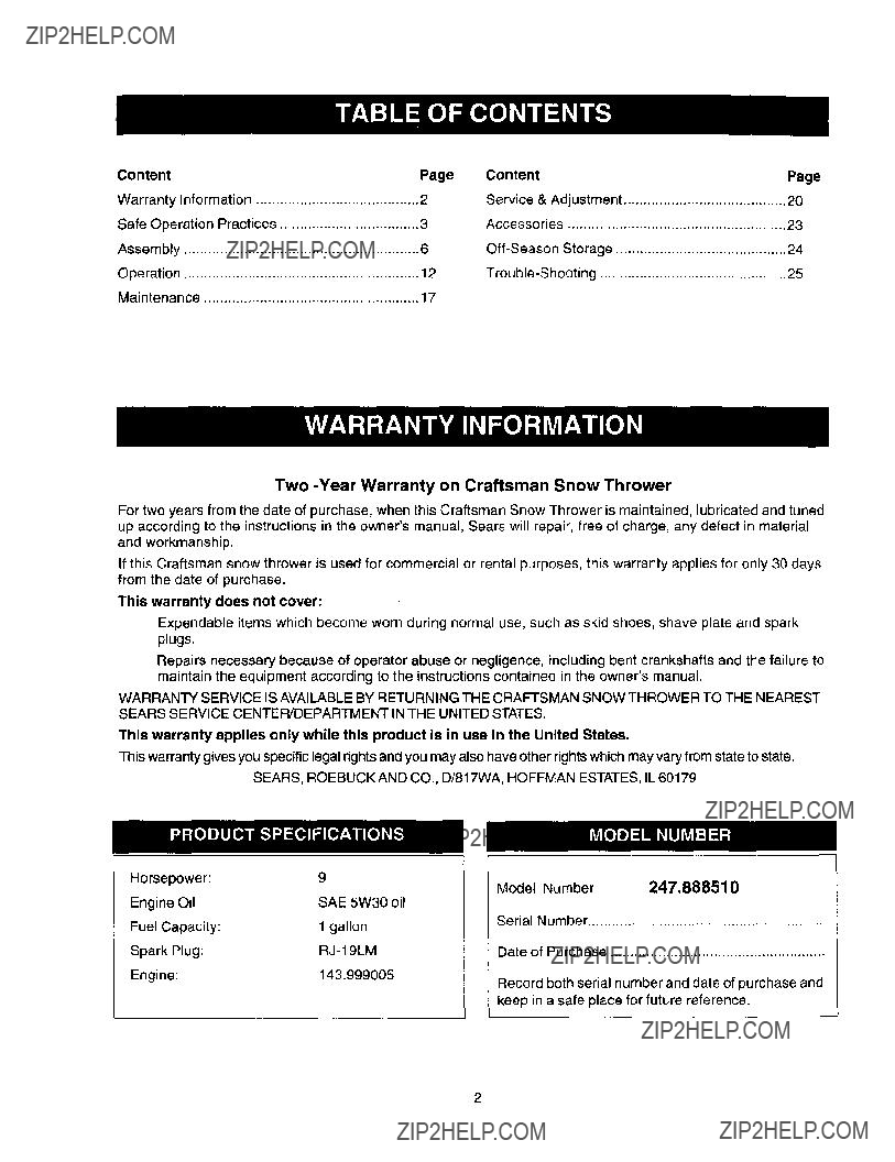
Two
For two years from the date of purchase, when this Craftsman Snow Thrower is maintained, lubricated and tuned up according to the instructions in the owner'smanual, Sears will repair, free of charge, any defect in material and workmanship.
If this Craftsman snow thrower is used for commercial or rental purposes, this warranty applies for only 30 days from the date of purchase.
This warranty does not cover:
Expendable items which become worn during normal use, such as skid shoes, shave plate and spark plugs.
Repairs necessary because of operator abuse or negligence, including bent crankshafts and the failure to maintain the equipment according to the instructionscontained in the owner'smanual.
WARRANTY SERVICE IS AVAILABLE BY RETURNING THE CRAFTSMAN SNOW THROWER TO THE NEAREST
SEARS SERVICE CENTER/DEPARTMENT IN THE UNITED STATES.
This warranty applies only while this product is in use in the United States.
This warrantygives you specificlegalrightsand you may also have other rightswhichmay varyfrom state tostate.
SEARS, ROEBUCK AND CO., D/817WA, HOFFMAN ESTATES, IL 60179
Model Number 247.888510
Serial Number ...........................................................
Date of Purchase ......................................................
Record both serial number and date of purchase and keep in a safe place for future reference.
2
Your snow thrower was built to be operated according to the rules for safe operation in this manual. As
,_ DANG ER" with any type of power equipment carelessness or error on the part of the operator can result in serious injury. If you violate any of these rules, you may cause serious injury to yourself or others.
,_forestThis-unitcovered,isequippedbrush-coveredwithan
In the State of California the above is required by law (Section 4442 of the California Public Resources Code). Other states may have similar laws. Federal laws apply on federal lands. A spark arrester for the muffler is available through your nearest Sears Authorized Service Center (See the REPAIR PARTS section of this manual.)
TRAINING
Read thisowner'sguide carefully in its entirety before attempting to assemble or operate this machine. Be completely familiar with the controls and the proper use of this machine before operating it. Keep this manual in a safe place for future and regular reference and for ordering replacement parts.
Never allow children under 14 years old to operate a snow thrower. Children 14 years old and over should only operate a snow thrower under close parental supervision. Only persons well acquainted with these rules of safe operation should be allowed to use your snow thrower.
No one should operate this unit while intoxicated or
while taking medication that impairs the senses or reactions.
Keep the area of operation clear of all persons, especially small children and pets.
Exercise caution to avoid slipping or falling, especially when operating in reverse.
PREPARATION
Thoroughly inspect the area where the equipment is to be used and remove all door mats, sleds, boards, wires and other foreign objects.
Do not operate equipment without wearing adequate outer garments for winter. Do not wear jewelry, long scarfs or other loose clothing which could become entangled in moving parts. Wear footwear which will improve footing on slippery surfaces.
Before working with gasoline, extinguish all cigarettes and other sources of ignition. Check the fuel before starting the engine. Gasoline is an extremely flammable fuel. Do not fill the gasoline tank indoors, while the engine is running, or until engine has been allowed to cool at least two minutes. Replace
gasoline cap securely and wipe off any spilled gasoline before starting the engine as it may cause a fire or explosion.
Use a grounded three wire
Adjust collector housing height to clear gravel or crushed rock surface.
Never attempt to make any adjustments while engine is running (except where specifically recommended by manufacturer).
Let engine and machine adjust to outdoor temperature before starting to clear snow. Always wear safety glasses or eye shields during
operation or while performing an adjustment or repair, to protect eyes from foreign objects that may be thrown from the machine in any direction.
OPERATION
Do not put hands or feet near or under rotating parts.
Keep clear of discharge opening and auger at all times.
Exercise extreme caution when operating on or crossing gravel drives, walks, or roads. Stay alert for hidden hazards or traffic.
Do not carry passengers.
After striking a foreign object, stop the engine, remove wire from the spark plug and thoroughly inspect the snow thrower for any damage. Repair the damage before restarting and operating the snow thrower.
If the snow thrower starts to vibrate abnormally, stop the engine and check immediately for the cause. Vibration is generally a warning of trouble.
Stop the engine whenever you leave the operating position, before unclogging the collector/impeller housing or discharge guide and before making any repairs, adjustments, or inspections. Never place your
handinthedischargeorcollectoropeningsUsea. stickorwoodenbroomhandletounclogthe dischargeopening.
Takeallpossibleprecautionswhenleavingtheunit unattendedDisengagethecollector/impeller,stop.
theengineandremovethekey.
Whencleaning,repairing,orinspecting,makecertain
collectodimpellerandallmovingpartshavestopped. Disconnectsparkplugwireandkeepawayfromplug
topreventaccidentalstarting.
Donotruntheengineindoors,exceptwhenstartingit
and/ortransportingthesnowthrowerinoroutof
buildingOpendoorsbeforestartingtheenginethat.
caseExhaustfumesaredangerous.. DonotclearsnowacrossthefaceofslopesExercise.
extremecautionwhenchangingdirectionslopes.
Donotattempttodearsteepslopes.
Neveroperatethesnowthrowerwithoutguards,
platesorothersafetyprotectiondevicesinplace. Neveroperatethesnowthrowernearglass
enclosure,automobiles,windowwells,dropoff,etc., withoutproperadjustmentsofsnowthrower
dischargeaegteKeep. chitdren end pets away.
Do not overload machine capacity by attempting to clear snow at too fast a rate. Never operate the machine at high transport speeds on slippery surfaces. Look behind and use care when backing. Never direct discharge at bystanders or allow anyone in front of unit while throwing snow.
Disengage power to collector/impeller of the snow thrower when transporting it or when the unit is not in use. Use only attachments and accessories (such as wheel weights, counter weights, cabs, etc.) approved
by the snow thrower manufacturer.
Never operate the snow thrower without good visibility or light. Always be sure of your footing and keep a firm hold on the handles. Walk, never run.
Muffler and engine become hot and can cause severe burn injury. Do not touch the muffler or the engine while starting or operating the snow thrower.
MAINTENANCE ANDSTORAGE
Check shear bolts, engine mounting bolts, etc., at frequent intervals lor proper tightness, thus ensuring that the equipment is in safe working condition. Never store the machine with fuel in the fuel tank inside a building where ignition sources are present, such as hot water heaters, space heaters, clothes dryers and the like. Allow engine to cool before storing in any enclosure.
Always refer to owner's guide instructions for important details if the snow thrower is to be stored for an extendedperiod.
Run machine a few minutes after throwing snow to prevent
Chock clutch controls periodically to verify that these engage and disengage properly and readjust if necessary. Refer to Service and Adjustments section page of this owner'sguide.
YOUR RESPONSIBILITY
Restrict the use of this power machine to persons who read, understand and follow the warnings and instructions in this manual and on the machine.
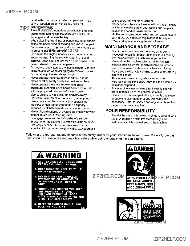
Fo ow ng are representations of some of the safety labels on your Craftsman snowthrower. Please follow the instruction on these labels and maintain safety while using or servicing the equipment.
,a kDANGER
[ kWARNING ]
DANGER
4
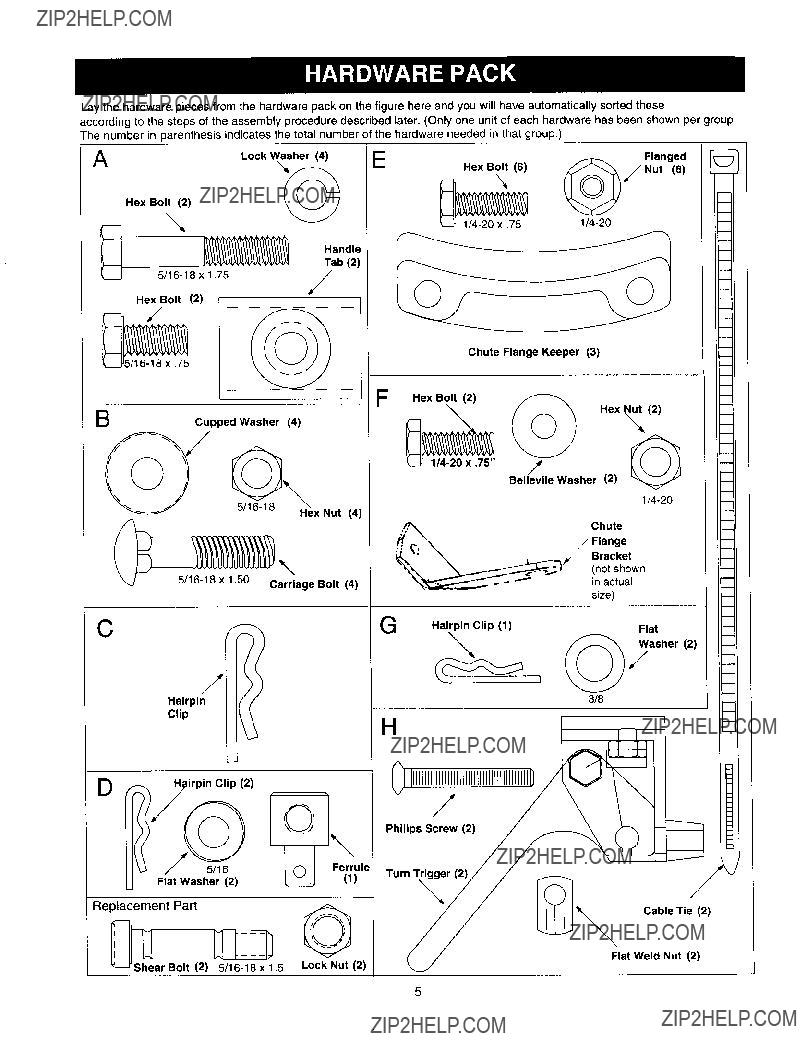
Lay the hardware pieces from the hardware pack on the figure here and you will have automatically sorted these
according to the steps of the assembly procedure described later. (Only one unit of each hardware has been shown per group. The number in parenthesis indicates the total number of the hardware needed in that group.)
A
Handle
Tab (2)
Hex Bolt (2)
Belle "e as e () __/
C
Hairpin
Clip
Replacement_shePart _
Cable Tie (2)
Flat Weld Nut (2)
ar Bolt (2)
Panel
Chute/
Rear
Left
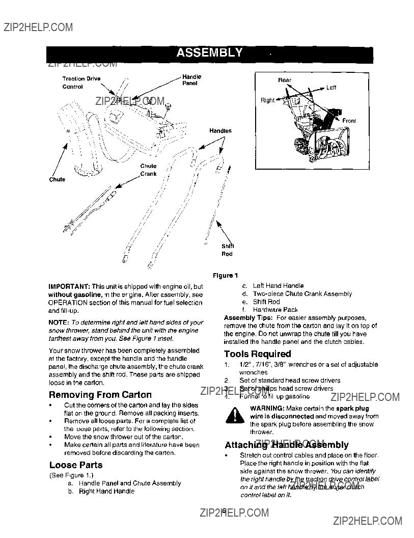
IMPORTANT: This unit is shipped with engine oil, but
without gasoline, in the engine. After assembly, see OPERATION section of this manual for fuel selection
and
NOTE: To determine right and left hand sides of your snow thrower, stand behind the unit with the engine farthest away from you. See Figure I inset.
Your snow thrower has been completely assembled at the factory, except the handle and the handle panel, the discharge chute assembly, the chute crank assembly and the shift rod. These parts are shipped loose in the carton.
Removing From Carton
???Cut the corners of the carton and lay the sides flat on the ground. Remove all packing inserts. Remove all loose parts. For a complete list of
the loose parts, refer to the following section. Move the snow thrower out of the carton.
???Make certain all parts and literature have been removed before discarding the carton.
Loose Parts
(See Figure 1.)
a.Handle Panel and Chute Assembly
b.Right Hand Handle
Rod
Figure I
c.Left Hand Handle
d.
e.Shift Rod
f.Hardware Pack
Assembly Tips: For easier assembly purposes, remove the chute from the carton and lay it on top of the engine. Do not unwrap the chute till you have installed the handle panel and the clutch cables.
Tools Required
1.1/2", 7/16", 3/8" wrenches or a set of adjustable wrenches
2.Set of standard head screw drivers
3.Set of philips head screw drivers
4.Funnel to fill up gasoline
A WARNING: Make certain the spark plug wire is disconnected and moved away from
the spark plug before assembling the snow thrower.
Attaching Handle Assembly
Stretch out control cables and place on the floor. Place the right handle in position with the flat side against the snow thrower. You can identify the right handle by the traction drive control label
on it and the left handle by the auger clutch control label on it.
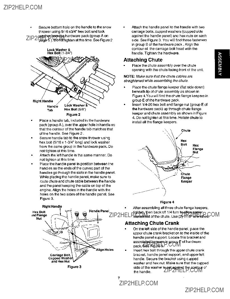
Secure bottom hole on the handle to the snow thrower using 5/16 x3/4" hex bolt and lock washer from the hardware pack (group A on page 5 ). Do not tighten at thistime. See Figure 2.
Lock Washer &
Hex Bolt
Place a handle tab, included in the hardware
pack (group A ), over the upper hole in handle so that the contour of the handle tab matches that
of the handle. See Figure 2.
Secure handle tab to the snow thrower using hex bolt (5/16 x
not tighten at this time.
Attach the left handle in the same manner. Do not tighten at this time.
Place the handle panel in position between the handles so the ends of the curved part of the handles go through the slots in the handle panel. While placing the handle panel, make sure to route chute and chute cable between the handle and the panel keeping the cable on top of the engine. Align the holes in the handle with the holes on the two sides of the handle panel. See
Figure 3.
Right Handle
Hex Bolt
[ndFlange Nut
1 Holes
Carriage Bolt,
and Hex Nut
Figure 3
NOTE: Make sure that the chute cables are
straightened while assembling the chute.
Place the chute flange keeper (flat side down) beneath lip of chute assembly as shown in Figure 4.You will find the chute flange keepers in group E of the hardware pack.
Insert
Chute
/
Hex
Bolt Hex
CKIheaU_g:r
Figure 4
After assembling all three chute flange keepers, tighten, then back off 1/4 turn to allow easier movement of the chute. Use (2) 7/16" wrenches.
Attaching Chute Crank
???On the left side of the handle panel, place the upper chute crank bracket on to the inside of the handle panel support. Locate this bracket and associated harware in group F of hardware pack. See Figure 5.
Insert hex bolt through the upper chute crank bracket, handle panel support, and upper left handle. Secure the bracket using cupped washer and hex nut. Make sure that the cupped
side of the washer is set against the contour of the handle.
7
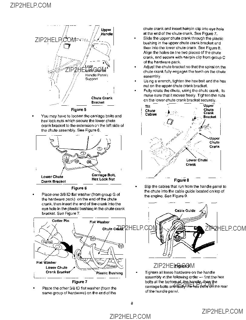
_ook
underthisfor i HandlePanel J
/ ,, Support
J
i
Chute Crank
Bracket
Figure 5
You may have to loosen the carriage bolts and hex lock nuts which secure the lower chute crank bracket to the extension on the left side of
the chute assembly. See Figure 6.
I
I
J
Figure 6
???Place one 3/8 ID flat washer (from group G of the hardware pack) on the end of the chute crank, then insert the end of the crank into the eye hole in the plastic bushing in the chute crank bracket. See Figure 7.
Chute Crank
Flat Washer
chute crank and insert hairpin clip into eye hole at the end of the chute crank. See Figure 7. Slide the upper chute crank through the plastic bushing in the upper chute crank bracket and then into the lower chute crank. See Figure 8. Align the holes on the two pieces of the chute crank, and secure with hairpin clip from group C of the hardware pack.
Adjust the chute bracket so that the spiral on the chute crank fully engages the teeth on the chute assembly.
Using a wrench, tighten the hex bolt and the hex nut on the upper chute crank bracket.
Fully rotate the chute, using the chute crank, to make sure that it moves freely. Tighten the nuts on the lower chute crank bracket securely.
Lower Chute
Crank
Figure 8
Slip the cables that run from the handle panel to the chute into the cable guide located on top of the engine. See Figure 9.
Cable Guide
L
Lower Chute/,r
Crank Bracket/astic Bushing
Figure 7
Figure 9
Tighten all loose hardware on the handle assembly in the following order
Place the other 3/8 ID flat washer (from the same group of hardware) on the end of the
of the handle panel.

Attaching Clutch Cables
The clutch control cables are attached to the snow thrower. If the cables are attached to the top of the
engine with cable ties, cut the cable ties now. The Z ends of the clutch cables are hooked into the clutch
grips on each handle.
???Ensure there is a hex jam nut threaded all the way up the threaded portion of the Z fitting; extras are supplied in the hardware pack. See Figure 10.
???Place the clutch grip in the raised (up) position.
Z Fitting
Outer portion of
Nut
Hex Jam
Nut
\
Ferrule
(Viewed from the
underside of the control panel)
Figure 10
Swing the left auger up making sure the cable is
routed correctly in the cable roller guides located at the lower rear of the unit.
Hold the end of the cable at the barrel so the ferrule turns freely without twisting the cable. Thread the ferrule on to the Z fitting. You may have to pull on the cable slightly to relieve
tension. Keep the ferrule turning without twisting the cable.
You will reach correct adjustment when there is minimal slack in the cable but it is not tight.Hold the flats on the ferrule with pliers and tighten the jam nut against the ferrule. CAUTION: Cables will become loose if you do not tighten the jam nut.
A WARNING: There must not be any tension on either clutch cable with the drive or auger clutch grip in the disengaged (up) position.
These clutches are a safety feature. Do not
override their function by allowing tension on either cable with the clutches
disengaged.
Attaching Shift Rod
???Place the shift lever in the sixth (6) speed.
Place the bent end of the shift rod into the hole in the shift arm assembly. See Figure 11. Secure with 5/16 flat washer and hairpin clip from the hardware pack (group D on page 5).
Start threading the ferrule (included in the same group in the hardware pack) onto the other end of the shift rod. It has to line up with the upper hole in the shift lever (beneath the handle panel). While aligning the ferrule, push down on the shift rod and the shift arm assembly as far as it will go. Once the ferrule slides into the hole, turn it
Rod
Assembly
Clip
Figure 11
NOTE: It may be necessary to pull the shift lever out of the sixth speed position and move it towards the fifth
speed position until the ferrule slides into the hole without force.
???Secure the ferrule to the shift lever with another 5/16 flat washer and hairpin clip from group D of the hardware pack. See Figure 11.
???Make certain to check for correct adjustment of the shift rod as instructed in the Adjustment section before operating the snow thrower.
Attaching Turn Triggers
???Make sure that the right hand trigger cable is routed in front of the traction drive cable.
Feed the trigger cable up through the outer side of the slot in the handle panel. Do notfeed the cable through the same side of the slot as the Z fitting.
???Place the cable barrel fitting into the hole in the trigger. You can find the triggers and associated

hardwareingroupHofthehardwarepack(on page5).Pullonthecableandrotateitaroundthe bottomofthetrigger,withtheinnercableinthe slot,untilthecableendcanbepushedintothe triggerhousingandsnappedtight.SeeFigure12.
Trigger
Assembly
Inner Cable
Trigger
Housing
Barrel Slot
Fitting
this end
Figure 12
Note: When the cable is installed correctly, it should not be possible to pull cable out of the trigger housing.
Place the right turn trigger in position underneath the right handle. Secure with screw and weld nut from group H of the hardware pack. See Figure 13. You will need a phillips screwdriver for tightening the screw. Repeat on left side.
Secure the right turn trigger cable to the right lower handle, using cable tie provided in the hardware pack. Make sure to route the cable tie over the drive cable. See Figure 14.
Trigger Cable
Figure 14
Secure the left turn trigger cable to the lower handle using the other cable tie. Make sure to route the cable tie below the auger drive cable so that when the trigger cable is secured by the cable tie, the auger drive cable is left outside the cable tie. Trim excess ends from each cable tie.
NOTE: The right side cable tie must be used to keep cable from coming in contact with the moving shift arm from the transmission.
Lamp Wiring
???Wrap the wire from the lamp down the right handle. See Figure 15. Plug wire into the alternator lead wire under the fuel tank (see inset).
aandle
_Trlgger.C+able
Figure 15
IMPORTANT: Assemble your snow thrower, then
check the adjustments as instructed and make any
final adjustments necessary before operating the unit.
Failure to foltowthe instructions may cause damage to the snow thrower.
Final Adjustments
Adjusting Auger Control
To check the adjustment of the auger control,
push forward the left hand clutch grip until the rubber bumper is compressed. There should be slack in the clutch cable.
Release the clutch grip. The cable should be straight. Make certain you can depress the auger control grip against the left handle completely.
If adjustment is necessary, loosen the hex jam nut and thread the cable in (for less slack) or out (for more slack).
10
RechecktheadjustmentTightenthejamnut.
againstthecablewhencorrectadjustmentis reached.
Adjusting Traction Drive Control
???To check the adjustment of the traction drive control and shift lever, move the weight transfer lever to the transport position (shown in on ) and the shift lever all the way forward to sixth (6) position.
With the traction drive control released, pull the triggers up to the handle and then push the snow thrower forward to check that the tracks turn.
???Squeeze traction drive controlagainst the handle and pull the starter.The tracks shouldturn.
???Now release the traction drive control and pull the starter again. The unit should not move. Before proceeding with adjustment, check to
make sure that the spark plug is disconnected.
???If the traction drive control needs adjustment,
loosen the jam nut on the traction drive cable and thread the cable one turn. Recheck
adjustment and repeat as necessary.
???Tighten the jam nut to secure the cable when correct adjustment is reached.
NOTE: Cables are out of adjustment if augers continue to tum when auger clutch is released and/or
Adjusting Skid Shoe
The space between the shave plate and the ground can be changed by adjusting the skid shoe.
???Return weight transfer lever to normal position before adjusting skid shoes.
???For close snow removal, adjust skid shoes higher to minimize gap between the shave plate and the ground.
???For snow removal from uneven ground like gravel, adjust skid shoes downward to create sufficient clearance between the bottom edge of shave plate and the ground. See Figure 16.
???Adjust the skid shoes by loosening the four hex nuts and carriage bolts and moving skid shoes to desired position. Make certain the entire bottom surface of skid shoe is against the ground to avoid uneven wear on the skid shoes. See Figure 16.
???Retighten nuts and bolts securely.
???Hex Nut
machine continues to run when drive clutch is
Skid
Carriage Bo t
released. For more details, refer to the Service and Adjustment section.
Figure 16
11
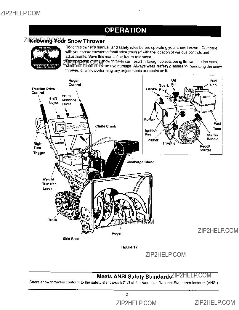
Knowing Your Snow Thrower
Read this owner'smanual and safety rules before operating your snow thrower. Compare with your snow thrower to familiarize yourself with the location of various controls and adjustments. Save this manual for future reference.
The operation of any snow thrower can result in foreign objects being thrown into the eyes, which can result in severe eye damage. Always wear safety glasses for operating the snow thrower, or while performing any adjustments or repairs on it.
Discharge Chute
Weight
Transfer
Lever
Track
/
Auger
Skid Shoe
Figure 17
Meets ANSI Safety Standards
Sears snow throwers conform to the safety standards B71.3 of the American National Standards Institute (ANSI).
12
Operating Controls
(See Figure 17.)
Chute Crank
The chute crank is located on the left hand side of the snow thrower. To change the direction in which snow is thrown, turn chute crank as follows:
turn clockwise to discharge to the left;
turn counterclockwise to discharge to the right.
Throttle Control
The throttle control is located on the engine. It regulates the speed of the engine.
Safety Ignition Switch
The ignition key must be inserted into the switch for the unit to start. Remove the ignition key when the snow thrower is not in use.
Left And Right Turn Trigger
The leftand right turn triggers are located on the underside of the handles and are used to assist in
steering your snow thrower. Squeeze the right turn trigger when turning right, squeeze the left turn trigger when turning left. Operate your snow thrower in open areas until you become familiar with these controls.
Shift Lever
The shift lever is located in the center of the handle panel. It may be moved into one of eight positions:
a.
b.
Use the shift lever to determine ground speed. Do not shift to different speed while the unit is moving.
Auger Control
The auger controlis located on the left handle. Squeeze the auger controlagainst the handle to engage the augers; release to disengage the augers. (Traction drive controlmust also be released.)
Traction Drive Control
The traction drive control is located on the right
handle. Squeeze the traction drive control to engage the track drive; release to stop.
This same lever also locks the auger control so that you can turn the chute crank without interrupting the snow throwing process. If the auger control is engaged with the traction drive controlengaged, you can release the auger control(on the left handle) and the augers will remain engaged. Release the traction drive controlto stop both the augers and the track drive. (Auger controlmust also be released).
Chute Distance Control
The distance that snow is thrown can be adjusted by
adjusting the angle of the chute assembly. Move the chute distance control forward to decrease the
distance, toward the rear to increase the distance.
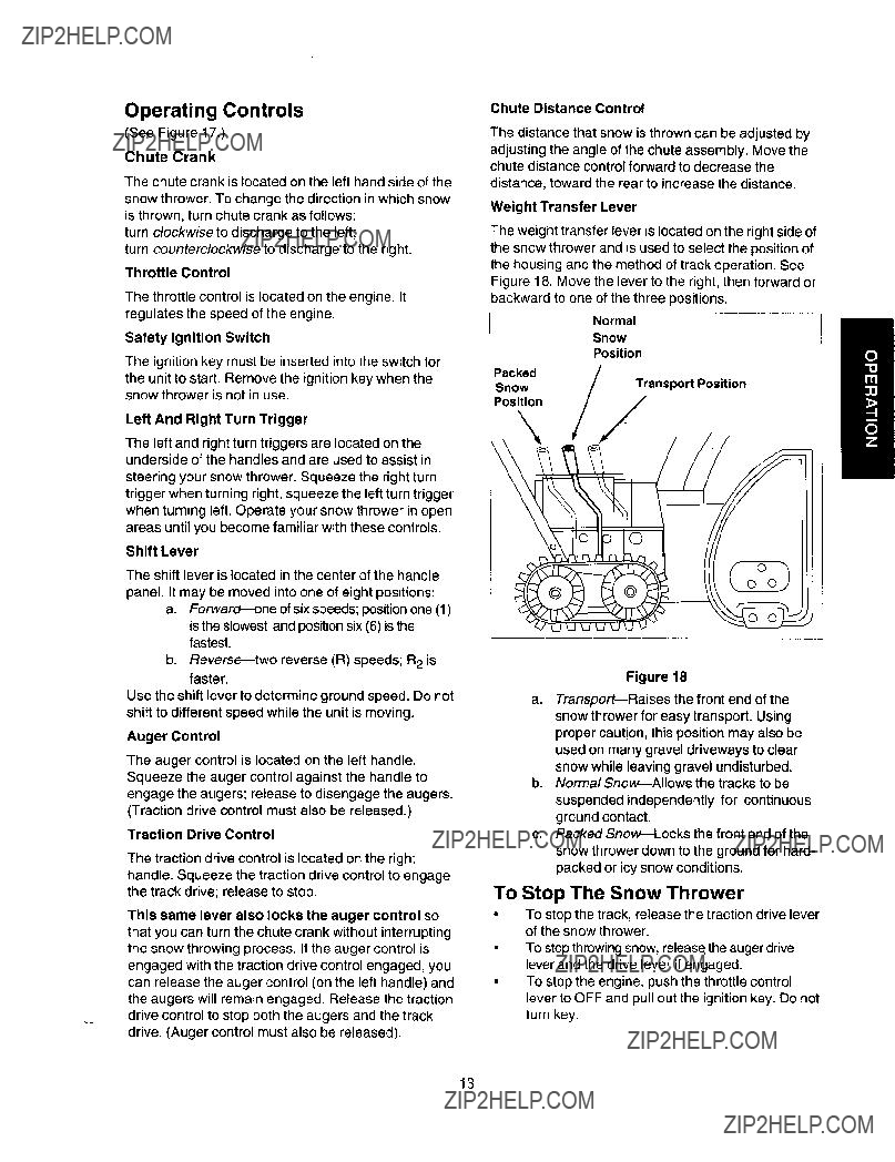
Weight Transfer Lever
The weight transfer lever is located on the right side of the snow thrower and is used to select the position of the housing and the method of track operation. See Figure 18. Move the lever to the right, then forward or backward to one of the three positions.
Normal
Snow
Position
iPacked
p%nOtiWon ._ans portPosition
Figure 18
a.Transport_Raises the front end of the snow thrower for easy transport. Using proper caution, this position may also be used on many gravel driveways to clear snow while leaving gravel undisturbed.
b.Normal
c.Packed
To Stop The Snow Thrower
To stop the track, release the traction drive lever of the snow thrower.
To stop throwingsnow, releas_the auger drive lever and the drive lever if engaged.
To stop the engine, push the throttle control lever to OFF and pull out the ignition key. Do not turn key.
13

Before Starting Engine
Fill Gas
WARNING: Gasoline is flammable and cau- tion must be used when handling or storing it.
Do not fillfuel tank while the snow thrower is running, when it is hot or when it is in an enclosed area.
Keep your snow thrower away from any open flame or an electrical spark and do not smoke while filling the fuel tank.
Never fill the fuel tank completely. Fill the tank to within
Always fill the fuel tank outdoors and use a funnel or spout to prevent spilling.
Make sure to wipe off any spilled fuel before starting the engine.
???Store gasoline in a clean, approved container and keep the cap in place on the container.
???Make sure that the container from which you pour the gasoline is clean and free from rust or other foreign particles.
???Fill fuel tank with clean, fresh, unleaded grade automotive gasoline.
???At the end of the job, empty the fuel tank if the snow thrower is not going to be used for 30 days
or longer. See storage instructions on of this manual.
CAUTION: Experience indicates that alcohol
blended fuels (called gasohol) or those using etha- nol or methanol can attract moisture which leads to
separation and formation of acids during storage.
Acidic gas can damage the fuel system of an engine while in storage.
To avoid engine problems, the fuel system should be emptied before storage for 30 days or longer. Drain the gas tank, start the engine and let it run until the fuel lines and carburetor are empty. Use fresh fuel next sea- son. See storage Instructions for additional information.
Starting Instructions at a glance_
Never use engine or carburetor cleaner products in the fuel tank or permanent damage may occur.
To Start Engine
A WARNING: Be sure no one other than the operator is standing near the snow
thrower while starting or operating. Do not operate this snow thrower unless the
discharge chute assembly has been properly installed and is secured.
A, Electric Starter
throttle
Figure 19
For location of all the engine controls referred to in this section, see Figure 19.
Before starting, make sure that the engine has suffi- cient oil. The snow thrower engine is equipped with a 120 volt A.C. electric starter and recoil starter. The electric starter is equipped with a
Cold Start
NOTE: If the unit shows any sign of motion (drive or augers) with the clutch grips disengaged, shut the engine off immediately. Readjust as instructed in the
14
"FinalAdjustments" section of the Assembly Instructions.
WARNING: The electric starter must be properly grounded at all times to avoid the possibility of elec- tric shock which may be injurious to the operator.
???Determine whether your house wiring is a three- wire grounded system. Ask a licensed electrician if you are not certain.
If your house wiring system is grounded and a
???When disconnecting the power cord, always unplug the end from the
???Attach spark plug wire to spark plug.
Make sure that the auger drive and the traction drive levers are in the disengaged RELEASED position.
???Move throttle control lever to FAST position.
???Remove the keys from the plastic bag. Push key into the ignition slot. Make sure it snaps into place. Do not turn key. Keep the second key in a safe place.
???Rotate the choke knob to FULL choke position.
???Connect the power cord to the switch box on the engine.
???Plug the other end of the power cord into a
starting the engine with an electric starter. ,_. WARNING: Do not use primerwhile
Push down on the starter button until the engine starts. Do not crank for more than 10 seconds at a time. This electric starter is thermally protected. If overheated, it will stop automatically and can be restarted only when it has cooled to a safe temperature (a wait of about 5 to 10 minutes is required).
When the engine starts, release the starter button and slowly rotate the choke to OFF position. If the engine falters, rotate the choke to FULL and then gradually to OFF.
Disconnect the power cord from the receptacle first and then from the switch box on the engine. Allow the engine to warm up for a few minutes because the engine will not develop full power
until it reaches operating temperature.
???Operate the engine at full throttle (FAST) when throwing snow.
Warm Start
If restarting a warm engine after a shut down, rotate choke to OFF instead of FULL and press the starter button.
B. Recoil Starter
Make sure that the engine has sufficient oil and the auger drive and the traction drive levers are released.
???Move throttle control to FAST position.
Push key into the ignition slot so that it snaps into place. Do not turn key. Remove plastic bag and keep the second key in a safe place.
???Rotate choke control to FULL choke position.
???Push the primer button while covering the vent hole. Remove your finger from the primer between primes. Do not prime if temperature is above 50oF; prime two times between 50o F and 15?? F; and prime four times below 15oF.
???Pull the starter handle rapidly. Do not allow the handle to snap back, but allow it to rewind slowly while keeping a firm hold on the starter handle. As the engine warms up and begins to operate evenly, rotate the choke knob slowly to OFF position. If the engine falters, return to FULL choke, then slowly move to OFF choke position.
???Allow the engine to warm up for a few minutes because the engine will not develop full power until it reaches operating temperature.
???Operate the engine at full throttle (FAST) when throwing snow.
Warm Start
If restarting a warm engine after a temporary shut down, rotate choke to OFF instead of FULL and do not prime. Press the starter button.
Frozen Recoil Starter
If the starter is frozen and will not turn the engine, proceed as follows:
Pull as much rope out of the starter as possible.
???Release the starter handle and let it snap back against the starter.
If the engine still fails to start, repeat the first two steps. If continued attempts do not free starter, follow the electric starter procedures to start. Avoid possible freezing of recoil starter and the engine controls.
Operating Snow Thrower
To Engage Drive
???With the engine running near top speed, move shift lever to one of six FORWARD positions or
15
twoREVERSEpositionsSelectaspeed.
appropriateforthesnowconditionsthatexist. Useslowerspeedsuntilyouarefamiliarwiththe operationofthesnowthrower.
???Squeezethetractiondriveclutchgripagainstthe righthandleandthesnowthrowerwillmove. Releaseitandthedrivemotionwillstop.
To Engage Augers
To engage the augers and start snow throwing, squeeze the left hand auger clutch grip against the left handle. Release to stop augers.
???While the auger control is engaged, squeeze the traction drive control to move, release to stop. Do not shift speeds while the drive is engaged.
NOTE: This same lever also locks the auger control so you can turn the chute crank without interrupting the snow throwing process.
???Release the auger control; the interlock mechanism should keep the auger control engaged until the traction drive control is released.
???Release the traction drive control to stop both the augers and the track drive.
must be released.
,_ WARNING: To stopthe auger, both levers
To Throw Snow
CAUTION: Check the area to be cleared for foreign
objects. Remove, if any.
Move the weight transfer lever to the right, then backward or forward to the desired position.
???Start the engine following Starting Instructions.
???Rotate the discharge chute to the desired
direction, away from bystanders and/or buildings. Move the chute distance control forward or
backward to adjust the distance the snow is to be thrown.
???Select the speed according to the snow condition.
CAUTION: Never move the shift lever without first releasing the drive clutch.
???Engage the auger control and traction drive
control levers following the preceding instructions.
???The interlock feature will allow you to remove your left hand from the auger control lever. When clearing the first pass through the snow, control the traction speed of the snow thrower according to the depth and condition of snow.
???To turn the unit left, squeeze left trigger; to turn right, squeeze right trigger.
On each succeeding pass, readjust the chute
deflector to the desired position and slightly overlap the previously cleared path.
After the area is cleared, stop the snow thrower following instructions given below.
Operating Tips
NOTE: Allow the engine to warm up for a few minutes as the engine will not develop full power until it reaches operating temperature.
surrounding areas may exceed 150 ?? F. Avoid _ Warning: The temperature of mufflerand
these areas.
???For most efficient snow removal, remove snow immediately after it falls.
???Discharge snow downwind whenever possible. Slightly overlap each previous swath.
???Set the skid shoes 1/4" below the scraper bar for normal usage. The skid shoes may be adjusted upward for
???Clean the snow thrower thoroughly after each use.
Before Stopping
???Run engine for a few minutes to help dry off any moisture on engine.
???To avoidpossible
Recoil Starter
a.With the engine running, pull the starter rope with a rapid, continuousfull arm stroke three or four times.
Electric Starter
a.Connect power cord to switch box, then to 120 Volt AC receptacle.
b.While the engine is running, push the starter button and spin the starter for several seconds.
c.Disconnect power cord from the receptacle first, then from the snow thrower.
NOTE: The unusual sound from pulling the starter
rope in the case of the recoil starter, or from spinning the starter in the case of the electric starter, will not
harm the engine.
To Stop The Snow Thrower
???To stop the track, release the traction drive lever on the snow thrower.
???To stop throwing snow, release auger drive lever and drive lever, if engaged.
To stop the engine, push throttle control lever to OFF and pull out the ignition key. Do not turn key.
16

General Recommendations
???Always observe safety rules when performing any maintenance.
The warranty on this snow thrower does not cover items that have been subjected to operator abuse or negligence. To receive full value from the warranty, operator must maintain the snow thrower as instructed in this manual.
???Some adjustments will have to be made periodically to maintain your unit properly.
???
A
AL
All adjustments in the Service and Adjustments section of this manual should be checked at least once each season.
Follow the maintenance schedule given below, Periodically check all fasteners and make sure these are tight.
WARNING: Always stop the engine and disconnect the spark plug wire before performing any maintenance or adjustments.
Customer Responsibilities
Lubricate pivot points
Clean snow thrower
o Clean shave plate
O.
Z tu
Clean skid shoes Check
Check friction wheel rubber
Check engine oil Change engine oil
Check spark plug Check muffler
Empty fuel system
* Fill in dates as you complete regular service ,_ Check; service if needed
17
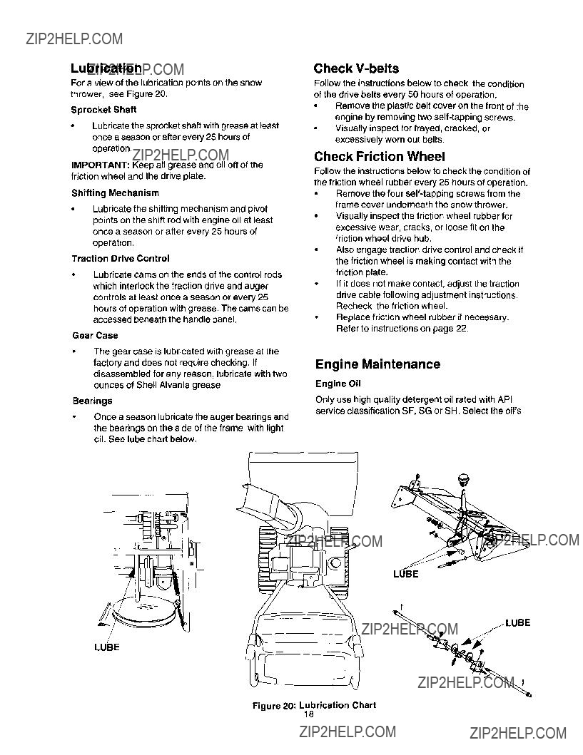
Lubrication
For a view of the lubrication points on the snow thrower, see Figure 20.
Sprocket Shaft
Lubricate the sprocket shaft with grease at least once a season or after every 25 hours of operation.
IMPORTANT: Keep all grease and oil off of the friction wheel and the drive plate.
Shifting Mechanism
Lubricate the shifting mechanism and pivot points on the shift rod with engine oil at least once a season or after every 25 hours of operation.
Traction Drive Control
???Lubricate cams on the ends of the control rods which interlock the traction drive and auger controls at least once a season or every 25 hours of operation with grease. The cams can be accessed beneath the handle panel.
Gear Case
???The gear case is lubricated with grease at the factory and does not require checking. If disassembled for any reason, lubricate with two ounces of Shell AIvania grease.
Bearings
Once a season lubricate the auger bearings and
the bearings on the side of the frame with light oil. See lube chart below.
Check
Follow the instructionsbelow to check the condition
of the drive belts every 50 hours of operation.
???Remove the plastic belt cover on the front of the engine by removing two
Check Friction Wheel
Follow the instructions below to check the condition of the friction wheel rubber every 25 hours of operation.
Remove the four
???Visually inspect the friction wheel rubber for excessive wear, cracks, or loose fit on the friction wheel drive hub.
???Also engage traction drive control and check if the friction wheel is making contact with the friction plate.
???If it does not make contact, adjust the traction
drive cable following adjustment instructions. Recheck the friction wheel.
???Replace friction wheel rubber if necessary. Refer to instructions on page 22.
Engine Maintenance
Engine Oil
Only use high quality detergent oil rated with API service classification SF, SG or SH. Select the oil's
II
Figure 20: Lubrication Chart
18

SAEviscositygradeaccordingtotheexpected operatingtemperature.
NOTE: Although
when used above 32??F. Check your snow thrower's engine oil level more frequently to avoid possible engine damage from running low on oil.
Refer to the viscosity chart for proper selection of engine oil.
Checking Oil Level
Before operating the snow thrower, check the oil level.
With engine on level ground, the oil must be to FULL mark on dipstick.
Stop engine and wait several minutes before
checking oil level. Remove oil fill cap and dipstick.
Wipe dipstick clean, insert it into oil fill hole and tighten securely.
Remove dipstick and check. If oil is not up to the FULL mark on dipstick, add 5W30 oil.
Changing Oil
Change engine oil after the first two hours of operation and every 25 hours thereafter.
In order to do that you will have to first drain the spent engine oil from the engine and then refill with fresh oil.
???Drain oil while engine is warm. Remove oil drain cap located at the bottom of the recoil starter of the engine. Catch oil in a suitable container.
When engine is drained of all oil, replace drain plug securely.
???Remove the dipstick from the oil fill tube. For location of the oil fill tube, see Figure 17 inset. Pour fresh oil slowly through the tube. Replace dipstick.
???Check and make sure that the level of oil is up to the FULL mark on the dipstick.
Spark Plug
Clean area around the spark plug base.
???Remove and inspect the spark plug.
???Replace the spark plug if electrodes are pitted, burned, or the porcelain is cracked. See Figure 21.
???Clean the spark plug and reset the gap to 0.030" at least once a season or every 50 hours of operation. See Figure 21.
???Spark plug replacement is recommended at the start of each season. Refer to engine parts list for correct spark plug type.
NOTE: Do not sandblast spark plug. Spark plug should be cleaned by scraping or wire brushing and washing with a commercial solvent.
Electrodes
Figure 21
19
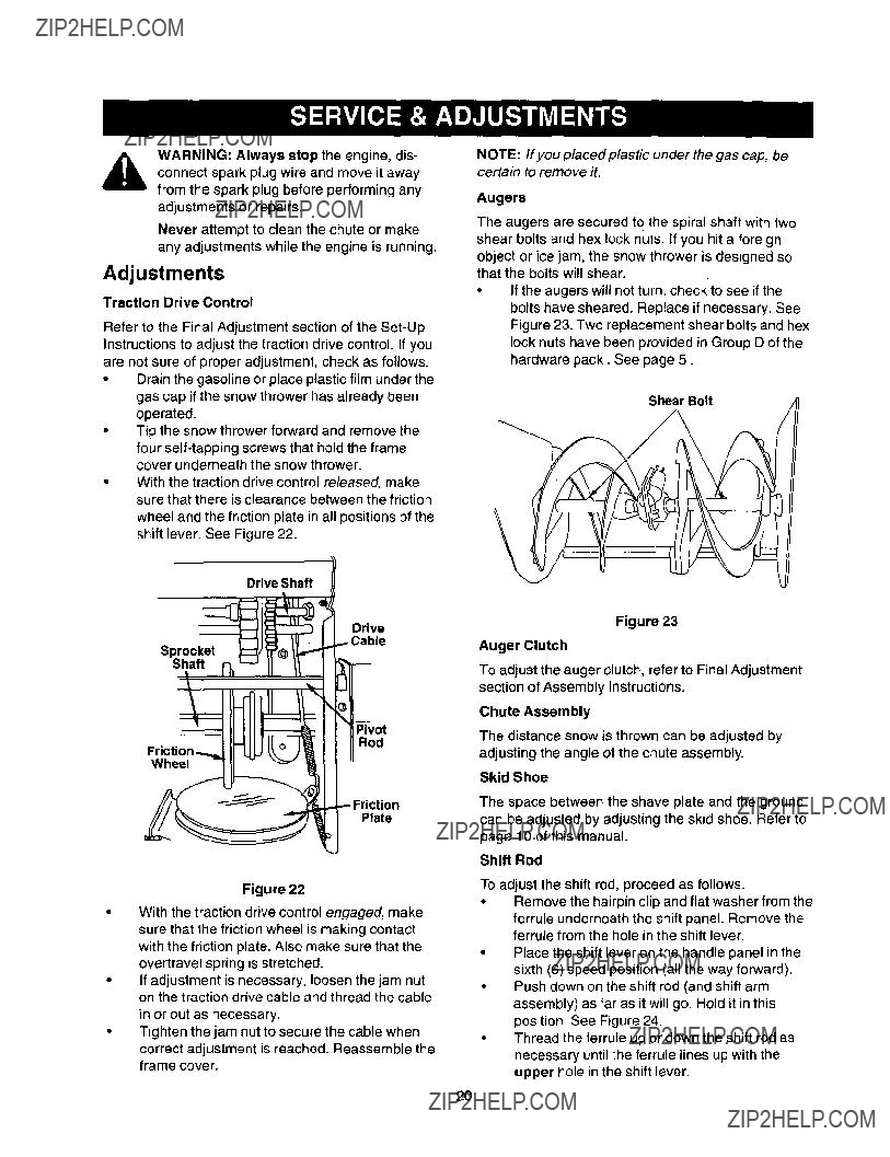
,& WARNING: Always stop the engine, dis- connect spark plug wire and move it away from the spark plug before performing any adjustments or repairs,
Never attempt to clean the chute or make any adjustments while the engine is running.
Adjustments
Traction Drive Control
Refer to the Final Adjustment section of the
???Drain the gasoline or place plastic film under the gas cap if the snow thrower has already been operated.
???Tip the snow thrower forward and remove the four
???With the traction drive control released, make sure that there is clearance between the friction wheel and the friction plate in all positions of the shift lever. See Figure 22.
Drive Shaft I
Drive
Sprocket
Shaft
Rod
Wheel
Plate
Figure 22
With the traction drive control engaged, make sure that the friction wheel is making contact with the friction plate. Also make sure that the overtravel spring is stretched.
If adjustment is necessary, loosen the jam nut on the traction drive cable and thread the cable
in or out as necessary.
Tighten the jam nut to secure the cable when correct adjustment is reached. Reassemble the frame cover.
NOTE: If you placed plastic under the gas cap, be certain to remove iL
Augers
The augers are secured to the spiral shaft with two shear bolts and hex lock nuts. If you hit a foreign object or ice jam, the snow thrower is designed so that the bolts will shear.
If the augers will not turn, check to see if the bolts have sheared. Replace if necessary. See Figure 23. Two replacement shear bolts and hex lock nuts have been provided in Group D of the hardware pack. See page 5.
Shear Bolt
\
Figure 23
Auger Clutch
To adjust the auger clutch, refer to Final Adjustment
section of Assembly Instructions.
Chute Assembly
The distance snow is thrown can be adjusted by adjusting the angle of the chute assembly.
Skid Shoe
The space between the shave plate and the ground can be adjusted by adjusting the skid shoe. Refer to page 10 of this manual.
Shift Rod
To adjust the shift rod, proceed as follows.
???Remove the hairpin clip and flat washer from the
ferrule underneath the shift panel. Remove the ferrule from the hole in the shift lever.
Place the shift lever on the handle panel in the sixth (6) speed position (all the way forward). Push down on the shift rod (and shift arm assembly) as far as it will go. Hold it in this position. See Figure 24.
???Thread the ferrule up or down the shift rod as necessary until the ferrule lines up with the upper hole in the shift lever.
2O
Spring
Washer
Rod
HakAssembly
Clip Flat
Washer
Figure 24
Insert the ferrule into the upper hole in the shift
lever from the right side when adjustment is correct. Secure with the flat washer and the
hairpin clip that you had earlier removed. See Figure 24.
Check for correct adjustment of the traction drive control as instructed in the Final
Adjustment section.
Service
Shave Plate And Skid Shoes
The shave plate and skid shoes on the bottom of the snow thrower are subject to wear. They should be checked periodically and replaced when necessary.
To remove skid shoes, remove the two carriage bolts, belleville washers and hex nuts (on each side) which attach them to the snow thrower.
Reassemble new skid shoes with the hardware
earlier removed. Make sure to insertthe cupped side of the washer against the skid shoe so that the skid shoe is adjusted to be level.
To remove shave plate, remove the carriage bolts, belleville washers and hex nuts which
attach it to the snow thrower housing. Reassemble new shave plate, making sure heads of the carriage bolts are to the inside of the housing. Tighten securely.
Belt Removal And Replacement
from the spark plug and ground it.
,_. WARNING: Disconnect the spark plug wire
Auger Drive Belts
Disconnect the chute crank at the chute
assembly by removing the cotter pin and the flat washer.
Remove the plastic belt cover on the front of the engine by removing two
Belt Cover
Screw
Figure 25
Unthread the bottom of the auger cable from the top of the cable, leaving the hex nut in place. Remove the six lock washers and hex nuts which attach the auger housing assembly to the frame. See Figure 26. (Only two pairs of lock washers and hex nuts are shown inthe figure.)
Lock Washer
and Hex Nut
Figure 26
Separate the housing from the frame assembly by standing in the operating position and lifting up on the handles. The frame and housing will separate and the rear auger drive belt will come off the pulleys.
21
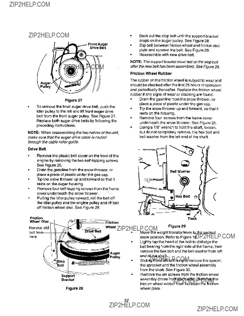
Drive Belt
Figure 27
To remove the front auger drive belt, push the idler pulley to the left and lift front auger drive belt from the front auger pulley. See Figure 27. Replace both auger drive belts by following the preceding instructions.
NOTE: When reassembling the two halves of the unit, make sure that the auger drive cable is routed through the cable roller guide.
Drive Belt
???Remove the plastic belt cover on the front of the engine by removing the two
???Drain the gasoline from the snow thrower, or place a piece of plastic under the gas cap.
???Tip the snow thrower up and forward so that it rests on the auger housing.
Remove four
???Pulling the idler pulley upward, roll the belt off the idler pulley and the engine pulley and lift belt off friction wheel disc. See Figure 28.
Back out the stop bolt until the support bracket drops on the auger pulley. See Figure 28.
Slip belt between friction wheel and friction disc
plate and remove the belt. See Figure 28. Reassemble with new drive belt.
NOTE: The support bracket must rest on the stop bolt after the new belt has been assembled. See Figure 28.
Friction Wheel Rubber
The rubber on the friction wheel is subject to wear and should be checked after the first 25 hours of operation and periodically thereafter. Replace the friction wheel rubber if any signs of wear or cracking are found.
???Drain the gasoline from the snow thrower, or place a piece of plastic under the gas cap.
???Tip the snow thrower up and forward, so that it rests on the housing.
???Remove four screws from the frame cover underneath the snow thrower. See Figure 25.
???Using a 7/8" wrench to hold the shaft, loosen,
but do not completely remove, the hex bolt and bell washer from the left end of the shaft.
Bell Washer
Hex Bolt
Figure 29
Move the weight transfer lever to the packed snow position. Refer to Figure 18.
Lightly tap the head of the bolt to dislodge the
ball bearing from the right side of the frame; then remove the hex bolt and the bell washer from left
end of the shaft.
Sliding the shaft to the right, remove the spacer, the sprocket and the friction wheel assembly from the shaft. See Figure 30.
Remove the six screws from the friction wheel
assembly (three from each side). Remove the friction wheel rubber from between the friction
wheel plate.
22
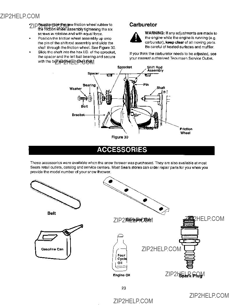
???Reassemblethenewfrictionwheelrubberto thefrictionwheelassemblytighteningthesix screwsinrotationandwithequalforce.
???Position the friction wheel assembly up onto
the pin of the shift rod assembly and slide the shaft through the friction wheel. See Figure 30.
???Slide the shaft into the hex I.D. of the sprocket, the spacer and the left ball bearing and secure with the bell washer and hex bolt.
Carburetor
WARNING: If any adjustments are made to the engine while the engine is running (e.g.
carburetor), keep clear of all moving parts. Be careful of heated surfaces and muffler.
If you think the carburetor needs to be adjusted, see your nearest authorized Tecumseh Service Outlet.
Shift Rod
Assembly
Bearin,
Washer
\
Friction
Wheel
Figure 30
These accessories were available when the snow thrower was purchased. They are also available at most Sears retail outlets, catalog and service centers. Most Sears stores can order repair parts for you when you provide the model number of your snow thrower.
Belt
Scraper Bar
23
ifyoursnowthrowerisleftunusedfor30daysor
longer,itneedstobepreparedforstorageAlso,at.
theendofthesnowseason,youshouldfollowthe samesetofinstructionsandstorethesnowthrower
Preparing Engine
WARNING: Never store snow thrower with fuel in tank indoors or in poorly ventilated areas, where fuel fumes may reach an open flame, spark or pilot light as on a furnace, water heater, clothes dryer or gas appliance.
It is important to prevent gum deposits from forming in essential fuel system parts of the engine such as the carburetor, fuel filter, fuel hose or tank during storage.
Also experience indicates that alcohol blended fuels (called gasohol or using ethanol or methanol) can attract moisture which leads to separation and formation of acids during storage. Acidic gas can damage the fuel system of an engine while in storage.
To avoid engine problems, the fuel system shouldbe emptiedbefore storage for 30 days or longer. Follow these instructions to prepare your snow thrower for storage:
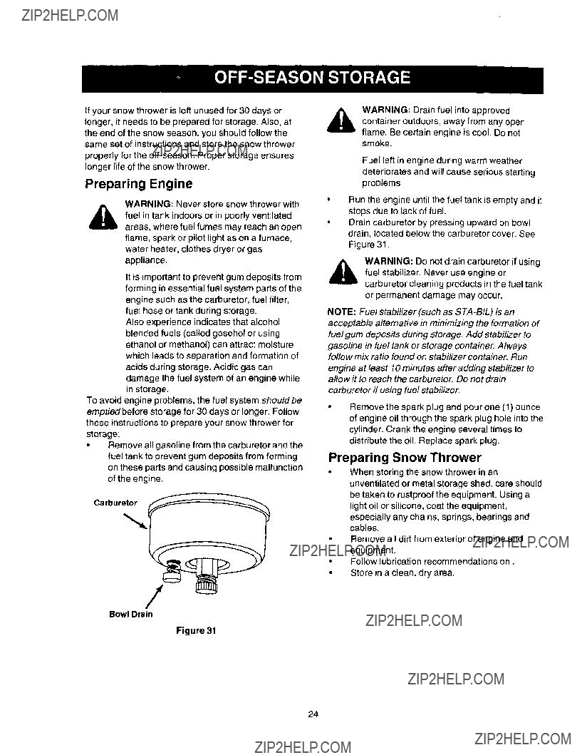
???Remove all gasoline from the carburetor and the fuel tank to prevent gum deposits from forming on these parts and causing possible malfunction of the engine.
Bowl Drain
Figure 31
WARNING: Drain fuel into approved container outdoors, away from any open flame. Be certain engine is cool. Do not smoke.
Fuel left in engine during warm weather deteriorates and will cause serious starting problems,
Run the engine until the fuel tank is empty and it stops due to lack of fuel.
Drain carburetor by pressing upward on bowl drain, located below the carburetor cover. See Figure 31.
&WARNING: Do not drain carburetor if using fuel stabilizer. Never use engine or
carburetor cleaning products in the fuel tank or permanent damage may occur.
NOTE: Fuel stabilizer (such as
gasoline in fuel tank or storage container. Always follow mix ratio found on stabilizer container. Run
engine at least 10 minutes after adding stabilizer to allow it to reach the carburetor. Do not drain
carburetor if using fuel stabilizer.
???Remove the spark plug and pour one (1) ounce of engine oil through the spark plug hole into the cylinder. Crank the engine several times to distribute the oil. Replace spark plug.
Preparing Snow Thrower
???When storingthe snow thrower in an unventilated or metal storage shed, care should be taken to rustproof the equipment. Using a light oil or silicone, coat the equipment, especially any chains, springs, bearings and cables.
Remove all dirt from exterior of engine and equipment.
Follow lubrication recommendations on. Store in a clean, dry area.
24
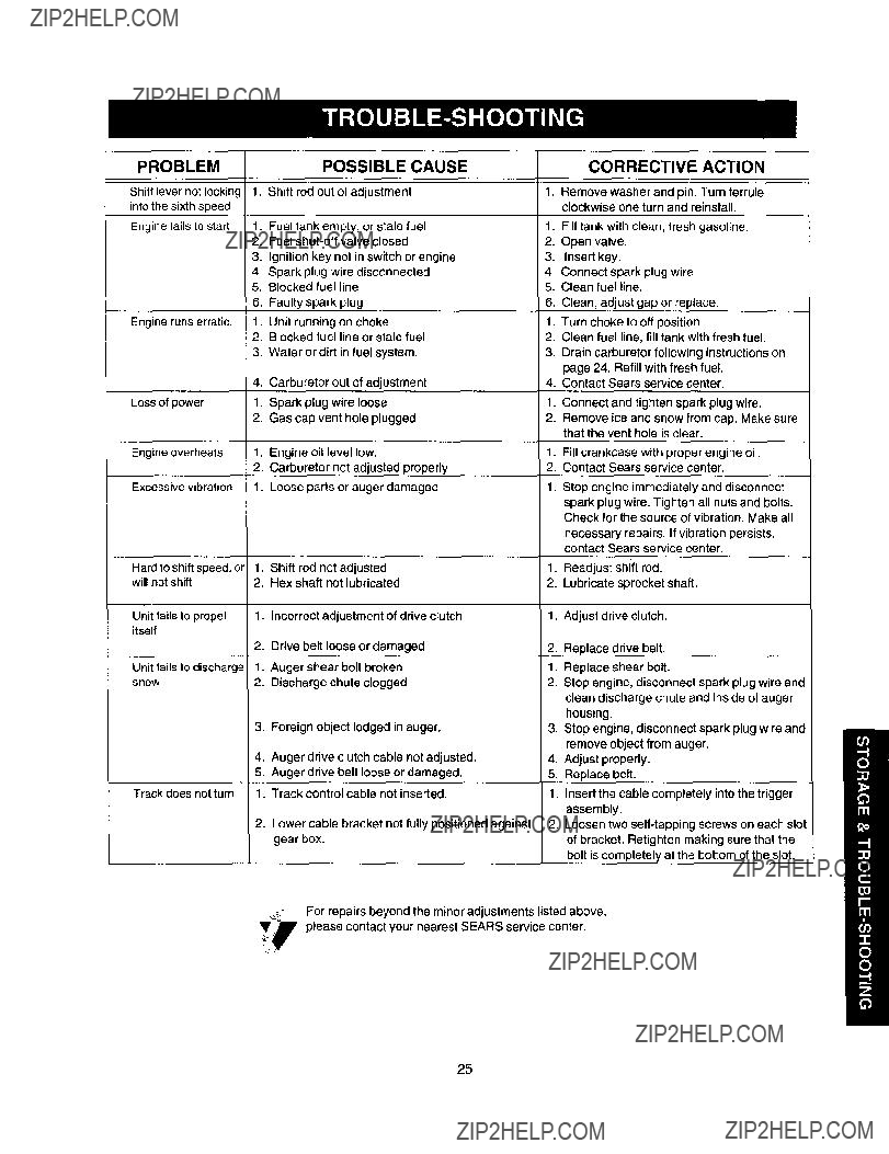
CORRECTIVE ACTION
Shift levernot locking intothe sixthspeed
Enginefailsto start
Engine runs erratic.
Loss of power
Engine overheats
Excessive vibration
1. Shift rod out of adjustment
1.Fuel tank empty, or stale fuel
2.Fuel
3.Ignition key not in switch or engine
4.Spark plug wire disconnected
5.Blocked fuel line
6, Faulty spark plug
1.Unit running on choke
2.Blocked fuel line or stale fuel
3.Water or dirt in fuel system.
4.Carburetor out of adjustment
1.Spark plug wire loose
2.Gas cap vent hole plugged
1.Engine oil level low.
2.Carburetor not adjusted properly
1.Loose parts or auger damaged
1.Remove washer and pin. Turn ferrule clockwise one turn and reinstall.
1.Fill tank with clean, fresh gasoline.
2.Open valve.
3.Insert key,
4.Connect spark plug wire.
5.Clean fuel line.
6.Clean, adjust gap or replace.
1.Turn choke to off position.
2.Clean fuel line, fill tank with fresh fuel.
3.Drain carburetor following instructions on page 24. Refill with fresh fuel
4.Contact Sears service center.
1.Connect and tighten spark plug wire.
2.Remove ice and snow from cap. Make sure that the vent hole is clear.
1.Fillcrankcase with proper engine oil.
2.Contact Sears service center.
1. Stop engine immediately and disconnect
spark plug wire. Tighten all nuts and bolts. Check for the source of vibration, Make all
necessary repairs, If vibration persists, contact Sears service center.
1.Readjust shift rod.
2.Lubricate sprocket shaft.
1.Adjust drive clutch.
2.Replace drive belt.
1.Replace shear bolt.
2.Stop engine, disconnect spark plug wire and clean discharge chute and inside of auger housing.
3.Stop engine, disconnect spark plug wire and remove object from auger.
4.Adjust properly.
5.Replace belt.
1.Insert the cable completely into the trigger
assembly.
2.Loosen two
25
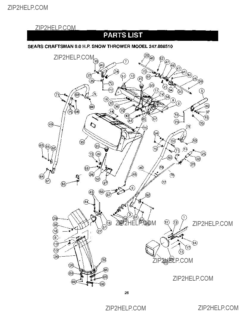
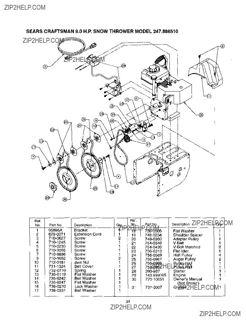
SEARS CRAFTSMAN 9.0 H.P. SNOW THROWER MODEL 247.888510
26
2
0637
Qty
1
1
Key Pad No.
No.
40
41
43
3
4
5
6
7
8
9
10
11
12
13
14
15
16
17
18
19
20
21
22
23
24
25
26
27
28
29
30
31
32
33
34
35
36
37
38
39
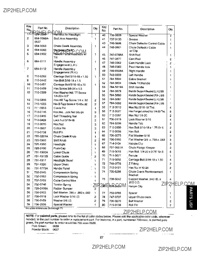
Chute Crank Assembly
Hardware Pack*
Handle Panel Assembly w/ Tilt
Handle Assembly
Engagement (LH.)
Handle Assembly Engagement (R.H.) Carriage Bolt
Hex AB Tap Screw 1/4 x .62
Clevis Pin
Hex Ins. Lock Nut
Self Threading Nut
Lock Nut
Hex Nut
Cotter Pin
Roll Pin
Chute Crank Knob
Shift Knob
Headlight
Push Cap
Lower Chute
Cable Guide
Headlight Bezel
Upper Chute
Handle Panel
Compression Spring
Compression Spring
Cable Control Wire
Torsion Spring
Rubber Bumper
Bell Washer .380 x ,880 x .062
Lock Washer 5/16 I.D.
Washer 5/6 I.D.
Special Washer
1
1
1
1
1
1
2
2
1
9
2
2
3
3
1
1
2
1
1
1
2
1
1
1
1
1
1
1
2
1
2
2
1
44
45
46
47
48
49
50
51
52
53
54
55
56
57
58
59
60
61
62
63
64
65
66
67
68
69
70
71
72
73
74
75
76
77
78
79
8O
* Includes references 58 through 75
NOTE: For painted parts, please refer to the list of color codes below. Please add the applicable color code, wherever
needed, to the part number to order a replacement part. For instance, if a part, numbered
Polo Green: 0689
Powder Black: 0637
27

SEARS CRAFTSMAN 9.0 H.P. SNOW THROWER MODEL 247.888510
\
@
28

9
10
17
18
19
20
21
22
23
24
25
27
28
29
30
33
36
37
38
39
40
NOTE: For painted parts, please refer to the list of color codes below. Please add the applicable color code, wherever needed, to the part number to order a replacement part. For instance, if a part, numbered
Polo Green: 0689
Powder Black: 0637
29

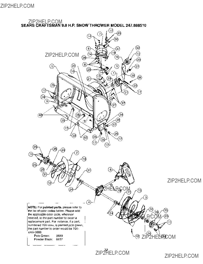
SEARS CRAFTSMAN 9.0 H.P. SNOW THROWER MODEL 247.888510
@
@
r??
3O
! NOTE: For painted parts, please refer to the list of color codes below. Please add the applicable color code,
[ wherever needed, to the part number to order a replacement part. For instance, if a part, numbered
i painted polo green, the part number to order would be
Powder Black: 0637
31
SEARS CRAFTSMAN 9.0 H.P, SNOW THROWER MODEL 247.888510
NOTE: For painted parts, please refer to the listof color codes below. Please add the applicable color code, wherever needed, to the part number to order a replacement part. For instance, if a part, numbered
Polo Green: 0689
Powder Black: 0637
32

Key Part No.
No.
1 05931
2
3
4
5
6
7
8
9
10
11
12
13
14
15
16
17
18
19
Description
Bearing Housing
Spiral Assembly
Spiral Assembly
Auger Gear Assembly
Spiral Housing Assembly
Impeller Assembly
Chute Reinforcement
Carriage Screw
Carriage Bolt
Hex
Shear Bolt
Jam Lock Nut
Toplock Nut
Hex Lock Nut
Hex Nut
Hex Nut
Spiral Pin
Chute Adapter
I I
33
SEARS CRAFTSMAN 9.0 H.P. SNOW THROWER MODEL 247.888510
34
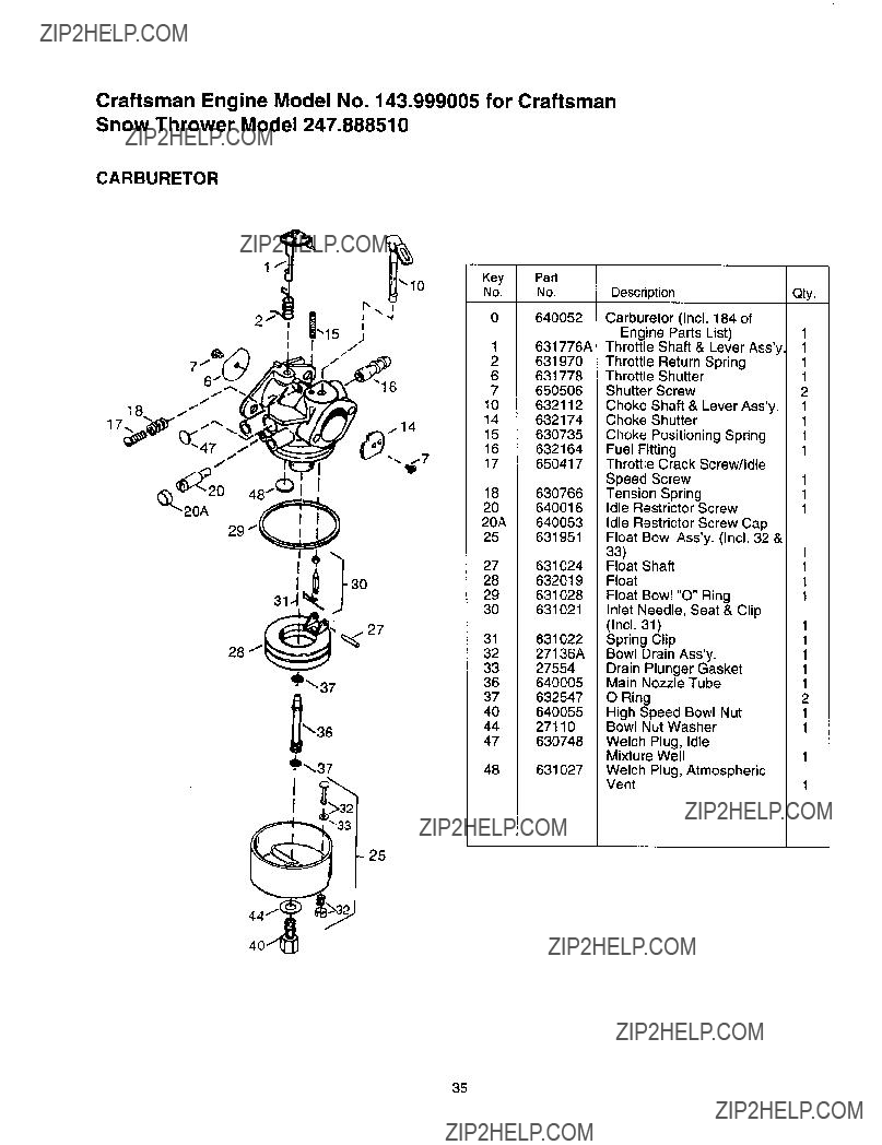
Craftsman Engine Model No. 143.999005 for Craftsman Snow Thrower Model 247.888510
CARBURETOR
,_,,27
_'37
_36
'1_,_37
I
I
]3
25
Key Pad
No. No.
0 640052
27631024
28632019
29631028
30631021
3231 27136A631O22
33 27554
36640005
37632547
40 640055
44 27110
47630748
48631027
DescriptionQty.
Welch Plug, Atmospheric
Vent
35
Craftsman Engine Model No, 143.999005 for Craftsman Snow Thrower Model 247,888510
305
>300
18
\
17 _
87
70
83
L40
3O
69
100
224_
25
26
182
110A
343
/ 206 ..- "/
3"t0G
328 [_370H
285 92_/. '_O
3_ /
282
370C
90G
36
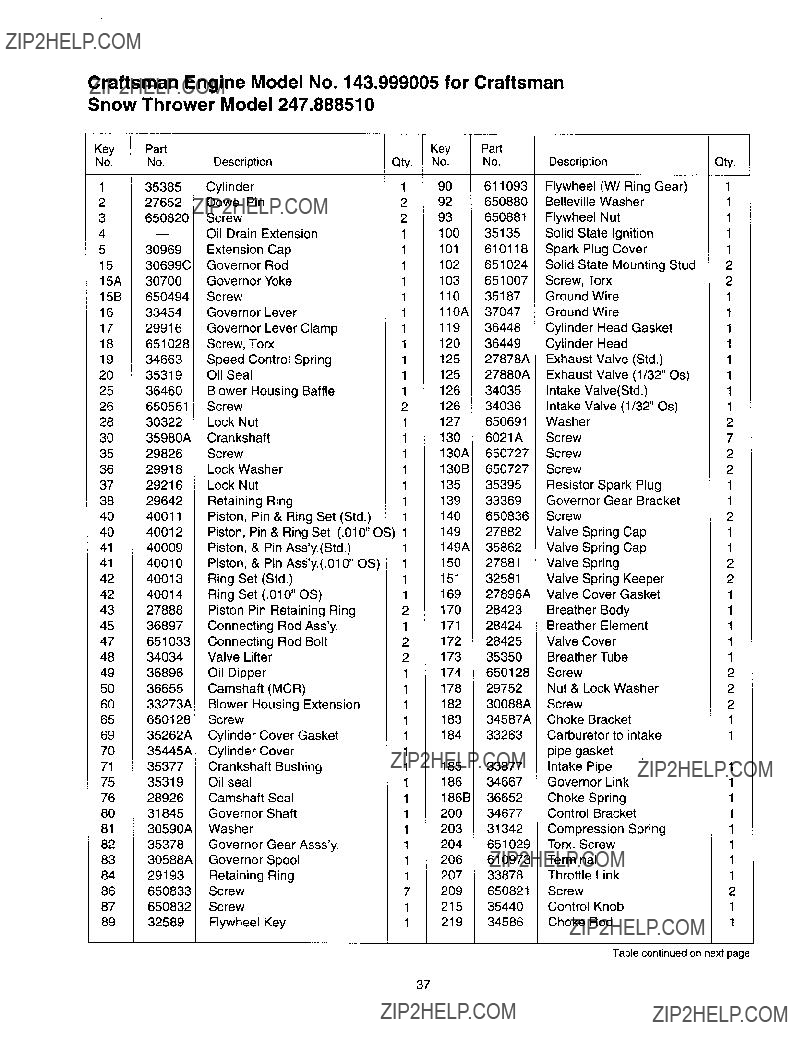
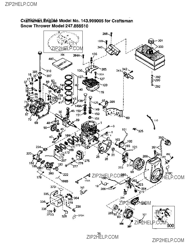
Craftsman Engine Model No. 143.999005 for Craftsman Snow Thrower Model 247,888510
Key Part
No. No.
135385
227652
3650820
530969
1530699C
15A 30700
15B 650494
1633454
1729916
18651028
1934663
20 35319
25 36460
26 650561
28 30322
30 35980A
3529826
3629918
3729216
3829642
4040011
4O 40012
4140009
41 40010
4240013
4240014
4327888
45 36897
47651033
4834034
4936896
7535319
7628926
8031845
8130590A
8235378
8330588A
84 29193
86650833
87650832
89 32589
Table continued on next page
37
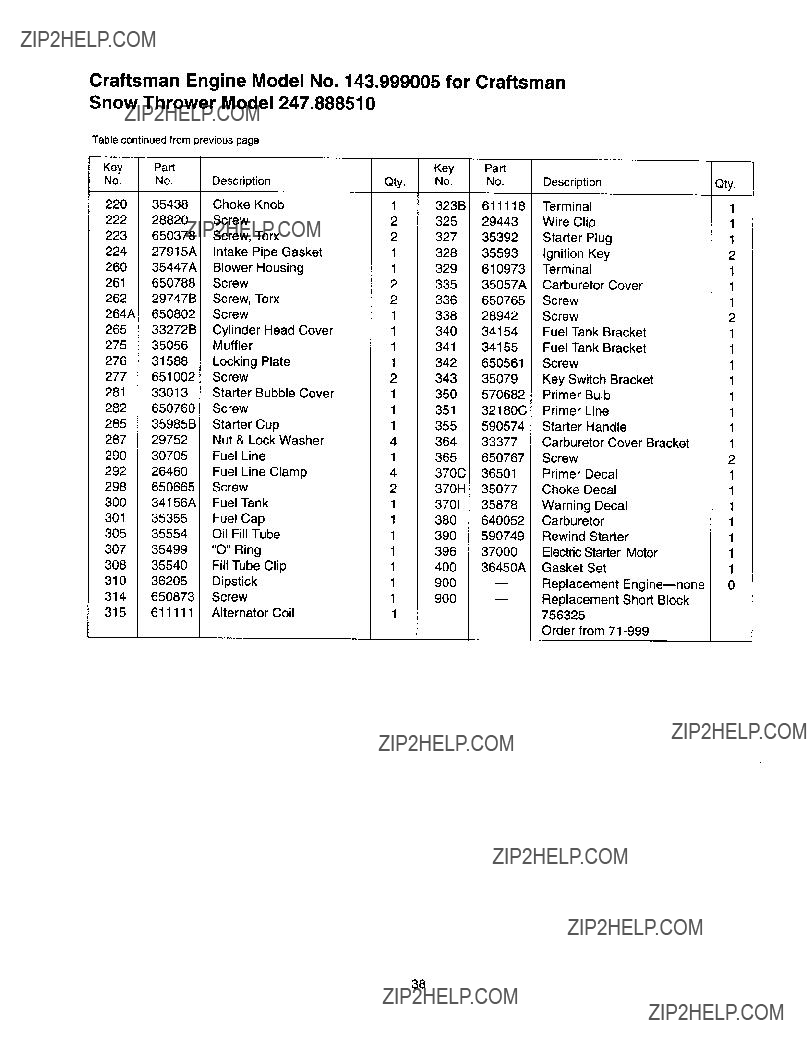
Craftsman Engine Model No, 143.999005 for Craftsman Snow Thrower Model 247,888510
Table continued from previous page
Qty.
1
1
1
2
1
1
1
2
1
1
1
1
1
1
1
1
2
1
1
1
1
1
1
1
0
38
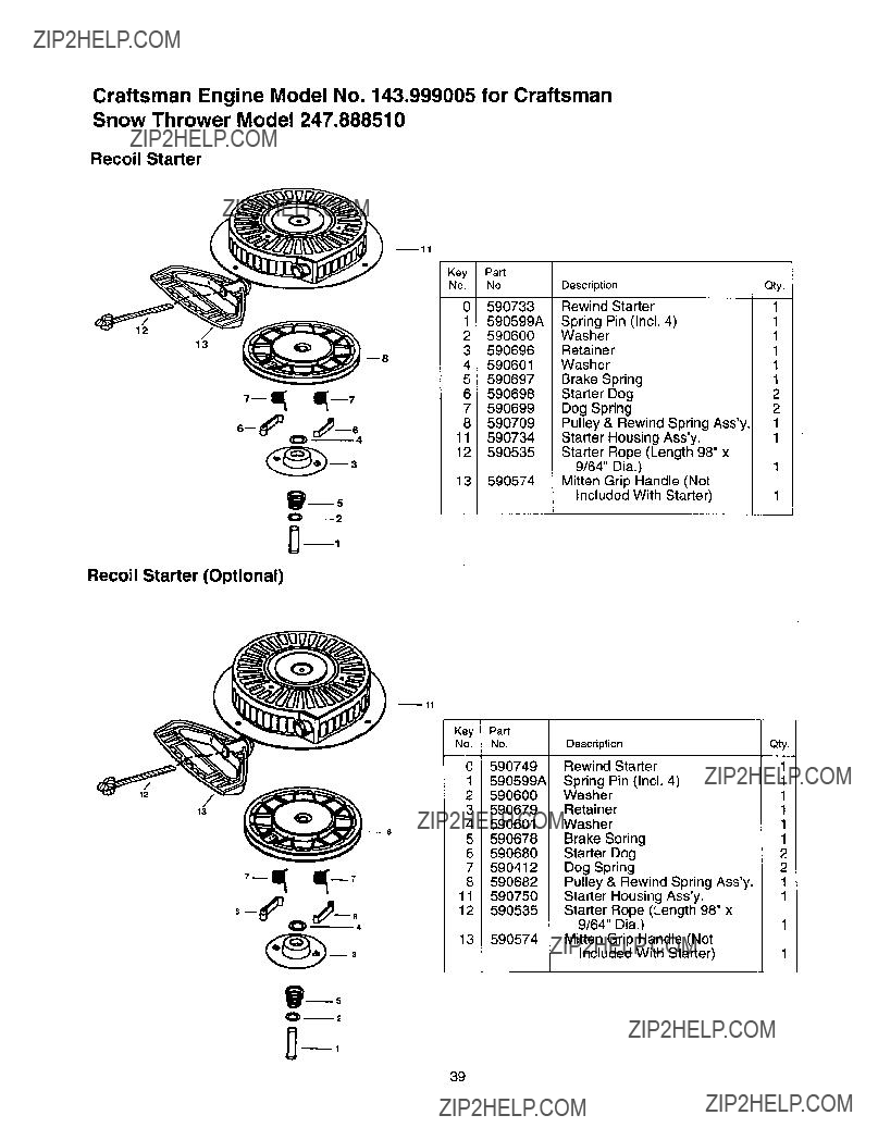
Craftsman Engine Model No. 143.999005 for Craftsman
Snow Thrower Model 247,888510
Recoil Starter
mll
Recoil Starter (Optional)
13
39
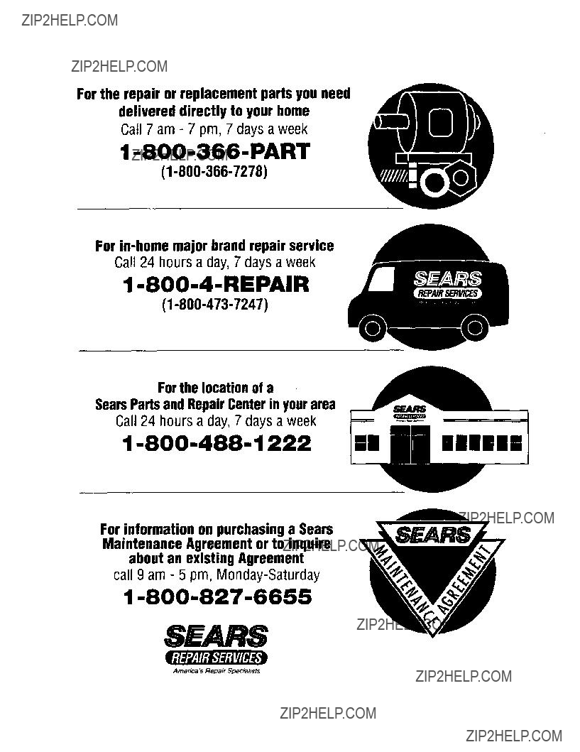
For the repair or replacement parts you need delivered directly to your home
Call 7 am - 7 pm, 7 days a week
For
Call 24 hours a day, 7 days a week
Forthe locationof a SearsPartsandRepairCenterin yourarea
Call 24 hours a day, 7 days a week
For information on purchasinga Sears Maintenance Agreement or to inquire about an existing Agreement
call 9 am - 5 pm,
Immmmm
mm|m|
Amenca LsRepair SPecialists