Owner's Manual

I CRAFI'SMAN+

SLEEVE HITCH

Model No. 486.24535

CAUTION:

Before using this product, read this manual and follow all

Safety Rules and

Operating Instructions.

IMPORTANT - READ THIS FIRST!!!

For Missing Parts or Assembly Questions

Please Call 866-576-8388

Mon.-Fri. 7 am - 5 pm CST.

FAX 217-728-2032 or e-mail info@agri-fab.com

Missing parts will be sent UPS in 24 hours directly to your home.

Sears, Roebuck and Co., Hoffman Estates, IL 60179 U.S.A. www.sears.com/craftsman

???Safety

???Assembly

???Operation

???Maintenance

???Parts

LIMITED ONE YEAR WARRANTY ON CRAFTSMAN SLEEVE HITCH

For one year from the date of purchase, when this sleeve hitch is maintained and lubricated according to the

operating and maintenance instructions in the owner'smanual, Sears will repair any defect in material or work- manship free of charge. If this sleeve hitch is used for commercial or rental purposes, this warranty applies for only 90 days from the date of purchase.

This warranty does not cover repairs necessary because of operator negligence or abuse, including the failure to maintain the equipment according to instructions contained in the owner's manual.

WARRANTY SERVICE IS AVAILABLE BY CONTACTING THE NEAREST SEARS SERVICE CENTER/DEPART-

MENT IN THE UNITED STATES.

This warranty applies only while this product is in the United States.

This warranty gives you specific legal rights, and you may also have other rights which vary from state to state. Sears, Roebuck and Co. D/817 WA. Hoffman Estates, Chicago, IL 60179

Any power equipment can cause injury if operated improperly or if the user does not understand how to operate the equipment. Exercise caution at all times, when using power equipment.

i_ Look for this symbol to point out important safety precautions. It means--Attention!! Become alert!! Your safety is involved.

The model number and serial numbers will be found on a decal attached to the frame.

You should record both the serial number and the date of purchase and keep in a safe place for future reference.

2

J

J

J

J

J

J

J

J

J

J

J

J

J

J

J

J

J

J

GJ

JF

H

L

J

J

KQ

J

MN

O

\\\

\\\

NOTE: Bolt (C), Lock Washer (N) and Nut (H) will not be used unless the mounting holes in the tractor do not already contain bolts and nuts.

Q3 Clevis Pin

R3 Hair Cotter Pin

3

CARTON CONTENTS

1.Sleeve Hitch Frame Assembly

2.Mounting Brackets (2)

3.Sleeve Hitch Lift Assembly

4.Hitch Pin with 5/32" Hair Cotter Pin

5.Lift Lever Assembly (with R.H. Pivot Bracket)

6.L.H. Pivot Bracket

Hardware Package (see page 3)

TOOLS REQUIRED FOR ASSEMBLY

(1)1/2" Wrench or Adjustable Wrench

(2)9/16" Wrenches or Adjustable Wrenches

(1)5/8" Wrench

(1)11/16" Wrench

(1)3/4" Wrench or Adjustable Wrench

(1)15/16" Wrenches or Adjustable Wrenches

Assemble the 5/16" hex nut and then the 5/16" lock washer onto the 5/16" x 1-3/4" carriage bolt. Screw the bolt into the nut welded to the stop bracket on the handle. The bolt is a depth adjustment for attached implements. See figure 1.

5/16" x 1-3/4" CARRIAGE BOLT 5/16" LOCK WASHER

5/16" HEX NUT

FIGURE1

???Remove the nuts from the two bolts in each side of the tractor, leaving the bolts in place. See figure 2.

???Attach the Mounting Brackets to the bolts using the

original nuts and two 3/8" flat washers. The brack- ets should be turned so that the bends increase the

distance between the rear of the brackets. See

Figure 2.

NOTE: If no bolt and nut are present in a hole, use a 3/8" x 1-1/4" hex bolt, 3/8" lock washer and 3/8" hex nut to attach the Mounting Bracket to the hole.

\

MOUNTING BRACKET

ORIGINAL NUT

FIGURE 2

Assemble a shoulder bolt to each mounting bracket using a 1/2" lock washer and 1/2" hex nut. See figure 3.

SHOULDER BOLT

MOUNTING BRACKET

FIGURE3

4

???PlacetheL.H.PivotBracketontotheendof the Lift

LeverAssembly(theR.H.PivotBracketcomes alreadyinstalledontheassembly)SeeFigure4. .

???AttachtheR.H.andL.H.PivotBracketstothe

SleeveHitchFrameAssemblyusingfour3/8"x 1" hexboltsand3/8"hexlocknuts.SeeFigure4.

LH. PIVOT BRACKET

???Assemble the two 5/8" jam nuts halfway onto the two 5/8" x 2-1/2" hex bolts. Screw the bolts into the nuts that are welded to the Sleeve Hitch Lift As- sembly. Snug the jam nuts against the welded nuts. See figure 6.

???Install the hitch pin in the sleeve hitch and secure it with a 5/32" hair cotter pin. See figure 6.

R.H. PIVOT BRACKET

HITCH PIN

5/32" HAIR

LIFT LEVER

ASSEMBLY

3/8-16 x 1"

HEX BOLT

3/8" NYLOCK NUT

SLEEVE HITCH FRAME

FIGURE 4

Hook the Sleeve Hitch Frame Assembly onto the shoulder bolts in the mounting brackets. Attach the bottom of the Assembly to the tractor hitch using a 5/8" x 1-3/4" hex bolt and a 5/8" nylock nut. See figure 5.

LIFT LEVER

FIGURE 5

COTTER PIN

5_"JAM NUT

5/8"x 2-1/2"

HEX BOLT

FIGURE 6

Attach the Sleeve Hitch Lift Assembly to the Sleeve Hitch Frame Assembly using three 5/8" x 1-3/4" clevis pins and 5/32" hair cotter pins as shown in figure 7.

......... -iiiiiiiiiiii.......

\

,,+(3)3/8"x 1-314"

:CLEVIS PINS

(3) 5/32" HAIR

COTTER PINS

FIGURE 7

5

???Move the lift lever backward to lower the sleeve hitch.

???Attach an implement using the sleeve hitch pin. Tighten the stabilizer bolts against the implement hitch and then tighten the jam nuts.

IMPORTANT: Some implements may require that the stabilizer bolts not be tightened. Refer to your implement owner's manual.

???Use the 5/16" x 1-3/4" carriage bolt to adjust the depth so that the attached implement is level front to back during operation.

???Clean off after each use.

???Oil pivot points as needed.

???Store in a dry location.

To remove the entire Sleeve Hitch attachment,

remove the 5/8" x 1-3/4" hex bolt and 5/8" nylock nut which fasten the bottom of the sleeve hitch to

the tractor hitch, then lift the attachment of the tractor.

To tow an implement that has a tow hitch, simply remove the three clevis pins and then remove the Sleeve Hitch Lift Assembly from the Sleeve Hitch Frame Assembly.

6

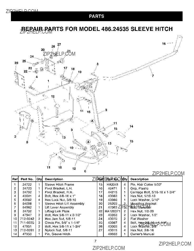
REPAIR PARTS FOR MODEL 486.24535 SLEEVE HITCH

27

26

2021

17 18

19

12

9

\f\

224723 1 Pivot Bracket, L.H.

324792 1 Pivot Bracket, R.H.

4 43001 4 Bolt, Hex 3/8-16 x 1"

543082 4 Hex Lock Nut, 3/8-16

664098 1 Sleeve Hitch Lift Assembly

764982 1 Lift Lever Assembly

824732 1 Lifting Link Plate

947947 2 Bolt, Hex 5/8-11 x 2-1/2" 10 712-0242 2 Hex Jam Nut, 5/8-11

11 711-0225 3 Clevis Pin, 5/8" x 1-1/4"

1247951 2 Bolt, Hex 5/8-11 x 1-3/4"

13712-0261 2 Nylock Nut, 5/8-11

1447950 1 Pin, Sleeve Hitch

15

\

Ref Part No. Qty Description

15HA3341 4 Pin, Hair Cotter 5/32"

1646471 1 Grip, Plastic

1744215 1 Carriage Bolt, 5/16-18 x 1-3/4"

1843083 1 Hex Nut, 5/16-18

1943086 1 Lock Washer, 5/16"

2343353 2 Lock Washer, 1/2"

2443070 2 Flat Washer

2543087 4 Bolt, Hex 3/8-16 x 1-1/4"

2643003 4 Lock Washer, 3/8"

2743015 4 Hex Nut, 3/8-16

49033 1 Owner's Manual

7

no matter who made it, no matter who sold it!

1-800-4-MY-HOME sMAnytime, day or night

(1-800-469-4663)

www.sears.com

To bring in products such as vacuums, lawn equipment and electronics for repair, call for the location of your nearest Sears Parts & Repair Center.

1-800-488-1222 Anytime, day or night

www.sears.com

For the replacement parts, accessories and owner's manuals

that you _eed tbodo-i_yourself, call Sears PartsDirectSM,

1 800 366 PART 6a.m.-11p.mCST.

www.sears.comlpartsdirect

SEARS

?? Registered Trademark / TM Trademark of Sears, Roebuck and CO.