CRRFTSMRN.
OWNERS
MANUAL
MODEL NO.
757.243481
Caution:
Read Rules for
Safe Operation and Instructions
Carefully
CRRFTSMRNo
LAWN AERATOR
FOR USE WITH RIDERS
AND LAWN/GARDEN TRACTORS
???Assembly
???Installation
???Operation
???Repair Parts
CRRFTSMRN.
OWNERS
MANUAL
MODEL NO.
757.243481
Caution:
Read Rules for
Safe Operation and Instructions
Carefully
CRRFTSMRNo
LAWN AERATOR
FOR USE WITH RIDERS
AND LAWN/GARDEN TRACTORS
???Assembly
???Installation
???Operation
???Repair Parts
LIMITED TWO YEAR WARRANTY ON AERATOR
For 2 years from the date of purchase, when this Aerator is maintained
and lubricated according to the operating and maintenance instructions in the owner's manual, Sears will repair, free of charge, any defect in material or workmanship.
This warranty does not cover:
purposes.
WARRANTY SERVICE IS AVAILABLE BY RETURNING TO THE NEAREST SEARS SERVICE CENTER/DEPARTMENT IN THE UNITED STATES. This warranty applies only while this product is in use in the United States.
This warranty gives you specific legai rights and you may also have other rights which vary from state to state.
SEARS, ROEBUCK AND CO., D/817 WA, Hoffman Estates, IL 60179, U.S.A.
CONGRATULATIONS on your purchase of a Sears Craftsman Aerator. It has been designed, engineered and manufactured to give you the best possible dependability and performance.
Should you experience any problem you can not easily remedy, please contact your nearest Sears Service Center/Department. We have competent, well trained technicians and the proper tools to service or repair, your Aerator.
Please read and retain this manual. The instructions will enable you to assemble and maintain your Aerator properly. Always observe the "SAFETY RULES".
???THE MODEL AND SERIAL NUMBERS WILL BE FOUND ON A DECAL ATrACHED TO THE FRONT
CORNER OF THE TRAY.
???YOU SHOULD RECORD BOTH SERIAL NUMBER
AND DATE OF PURCHASE AND KEEP IN A
SAFE PLACE FOR FUTURE REFERENCE.
MODEL
NUMBER757.243481
SERIAL
NUMBER
DATE OF
PURCHASE
CUSTOMER RESPONSIBILITIES
???Read and observe the "SAFETY RULES".
???Follow a regular schedule in maintaining, caring for and using your Coring Aerator.

RULES FOR SAFE OPERATION
??? Know controls and how to stop quickly, READ THE
OWNER'S MANUAL.
??? Do not allow children to operate the vehicle, do not allow adults to operate without proper instruction and without having read the owner's manual.
??? Do not carry passengers. Keep children and pets a safe distance away.
??? Always wear substantial footwear. Do not wear loose fitting clothing that can get caught in moving parts.
??? Keep your eyes and mind on your tract???r/attach- ment and area being covered. Don'tlet other interests distract you.
??? Stay alert for holes in the terrain and other hidden hazards.
???Keep the vehicle and attachment in good operating condition and keep safety devices in place.
???Keep all nuts, bolts and screws tight to be sure the equipment is in safe working condition.
???The vehicle and attachment should be stopped and inspected for damage after striking a foreign
object. The damage should be repaired before restarting and operating the equipment.
???See tractor equipment owner'smanual for safe
operation of the equipment.
??? Do not drive close to creeks, ditches and public
highways.
??? Watch out for traffic when crossing or near roadways.
???When using any attachment , don'tallow anyone near the vehicle while in operation.
A CAUTION
IT??? avoid damage to Spoons, always engage transport wheels to raise the Spoons when crossing concrete or asphalt w_ks, drives, or roads.
???Use the Aerator only on an established lawn, never on newly laid sod.
a To avoid possible personal injury and/or equipment never exceed the recommended operating speed range of 3 to 5 MPH.
???Only tow your Aerator behind vehicles for which it was designed, lawn/garden tractors.
???Do not stand/ride on Aerator, bodily injury could result.
???Never exceed the Weight Tray capacity of 150 pounds
???Do not attempt to disconnect Aerator from tractor with weight in Hopper.
???When backing, carefully back straight to avoid Jack- knifing, which could result in damage to equipment.
CONTENTS OF SHIPPING CARTON
1 Used
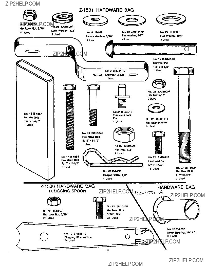
No. 5
lock Nut, 5116.
17 Used
%
No. 15
No. 2
Orawbar Clevis
1 Used
Tram_oort Lo_
NO. 29
Rat Wuher, 3/4"
3 Used
NO. 19
1/2" x
1 Used
Drswt)ar_in
NO 24 30M10GOP
Hex Nut 5/16"
2 Used
Handle Grip
1/4"x
5/1_'x
24 Used
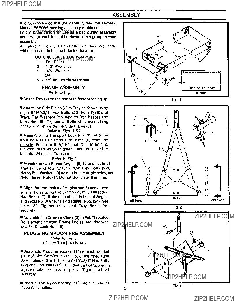
ASSEMBLY
It is recommended that you carefully read this Owner's
Manual BEFORE starting assembly of this unit.
Fold out the carton for use as a pad during assembly and arrange each kind of hardware into a group to ease assembly.
All reference to Right Hand and Left Hand are made while standing behind unit facing forward,
TOOLS REQUIRED FOR ASSEMBLY
1 - Pair Pliers
2 - 1/2" Wrenches
2 - 3/4" Wrenches
OR
2 - 10" Adjustable wrenches
FRAME ASSEMBLY
Refer to Fig. t
???Sit the Tray (7) on the pad with flanges facing up.
???Attach the Side Plates (6) to Tray as shown using
eight 5/16"x3/4" Hex Bolts (22- from INSIDE of Tray), Flat Washers (27- next to Bolt heads) and Lock Nuts (5). Tighten _11Bolts while maintaining 41" to
Refer to Figs. 1 &2
??? Assemble the Transport Lock Pin (31) into the front hole at Left Hand Side Plate (6) from the outside. Secure with 5/16" Lock Nut (5) holding Pin with Pliers as you tighten. This Pin is used to lock the Wheels in Transport.
Refer to Fig.2
??? Attach the two Frame Angles (8) to underside of Tray (7) using four 5/16" x 3/4" Hex Bolts (22), Heavy Flat Washers (9) next to Frame Angle holes, and Nylon Insert Nuts (5). Do not tighten at this time.
??? Align the front holes of Angles and fasten at two smaller holes using two
Hex Bolts (17). Bolts extend inside legs of Angles and secure with 5/16" Hex (regular) Nuts (24). See Inset "A". Tighten these and Tray Bolts (22) securely.
eAssemble the Drawbar Clevis (2) to Full Threaded Bolts extending from Frame Angles, securing with two 5/16" Lock Nuts (5).
PLUGGING SPOON
Refer to Fig. 3.
(Center Tube[ 14]shown)
Fig. 1
|7
o O
Fig. 2
22
32
??? Assemble Plugging Spoons (10) tO each welded plate (SIDES OPPOSITE WELDS) of the three Tube Assemblies (13 & 14) using 5/16"x3/4" Hex Bolts (22) and Lock Nuts (32). Rounded part of Spoon fits against tube to lock in place. Tighten all 24 securely.
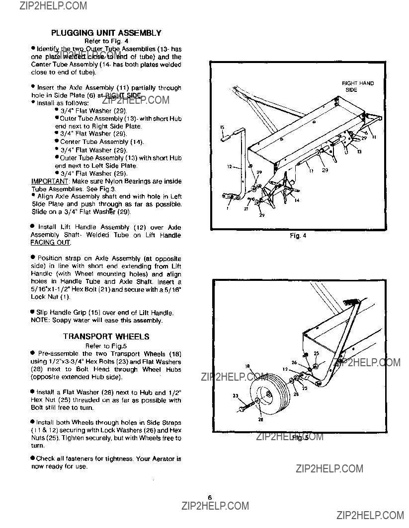
PLUGGING UNIT ASSEMBLY
Refer to Fig. 4
???Identify the two Outer Tube Assemblies (13- has one plate welded close to end of tube) and the Center Tube Assembly (14- has both plates welded close to end of tube).
???Insert the Axle Assembly (11) partially through hole in Side Plate (6) at RI.._HTSIDE.
???Install as follows:
??? 3/4" Flat Washer (29),
eOuter Tube Assembly (13)- with short Hub end next to Right Side Plate.
???3/4" Flat Washer (29).
???Center Tube Assembly (14).
???3/4" Flat Washer (29).
???Outer Tube Assembly (13) with short Hub end next to Left Side Plate.
???3/4" Flat Washer (29).
_:Make sure Nylon Bearings are inside Tube Assemblies. See Fig.3.
??? Align Axle Assembly shaft end with hole in Left Side Plate and push through as far as possible. Slide on a 3/4" Flat Washer (29).
??? Check all fasteners for tightness. Your Aerator is now ready for use.
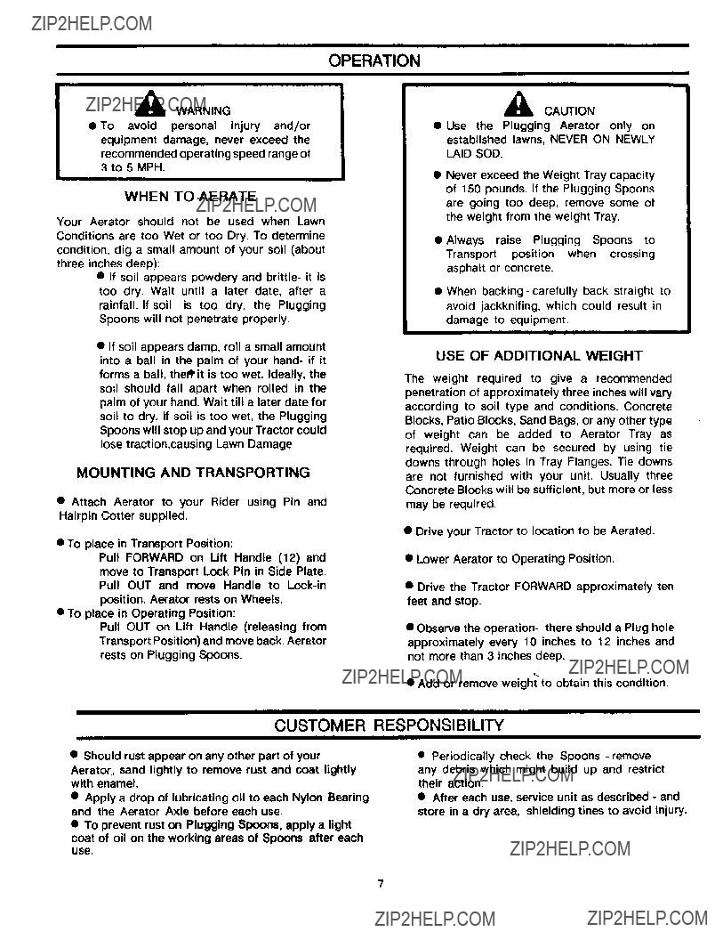
OPERATION
WARNING
???To avoid personal injury and/or equipment damage, never exceed the
recommended operating speed range of 3 to 5 MPH.
WHEN TO AERATE
Your Aerator should not be used when Lawn Conditions are too Wet or too Dry. To determine condition, dig a small amount of your soil (about three inches deep):
???If soil appears powdery and brittle- it is too dry. Wait until a later date, after a rainfall. If soil is too dry, the Plugging Spoons will not penetrate properly.
???If soil appears damp, roll a small amount into a ball in the palm of your hand- if it forms a ball, the_rit is too wet. Ideally, the
soil should fall apart when rolled in the palm of your hand. Wait till a later date for soil to dry. If soil is too wet, the Plugging Spoons will stop up and your Tractor could lose traction,causing Lawn Damage
MOUNTING AND TRANSPORTING
??? Attach Aerator to your Rider using Pin and Hairpin Cotter supplied.
??? To place in Transport Position:
Pull FORWARD on Lift Handle (12) and move to Transport Lock Pin in Side Plate. Pull OUT and move Handle to
??? To place in Operating Position:
Pull OUT on Lift Handle (releasing from
Transport Position) and move back. Aerator rests on Plugging Spoons.
,_ CAUTION
Use the Plugging Aerator only on established lawns, NEVER ON NEWLY
LAID SOD.
???Never exceed the Weight Tray capacity of 150 pounds. If the Plugging Spoons are going too deep, remove some of the weight from the weight Tray.
???Always raise Plugging Spoons to Transport position when crossing asphalt or concrete.
???When
USE OF ADDITIONAL WEIGHT
The weight required to give a recommended penetration of approximately three inches will vary according to soil type and conditions. Concrete Blocks, Patio Blocks, Sand Bags, or any other type of weight can be added to Aerator Tray as required. Weight can be secured by using tie downs through holes in Tray Flanges. Tie downs are not furnished with your unit. Usually three
Concrete Blocks will be sufficient, but more or less
may be required.
???Drive your Tractor to location to be Aerated.
???Lower Aerator to Operating Position.
???Drive the Tractor FORWARD approximately ten feet and stop.
???Observe the operation- there should a Plug hole approximately every 10 inches to 12 inches and not more than 3 inches deep.
???Add or remove weight to obtain this condition.
CUSTOMER RESPONSIBILITY
??? Should rust appear on any other part of your
Aerator,, sand lightly to remove rust and coat lightly with enamel.
???Apply a drop of lubricating oil to each Nylon Bearing and the Aerator Axle before each use.
???To prevent rust on Plugging Spoons, apply a light
coat of oil on the working areas of Spoons after each
use.
??? Periodically check the Spoons
??? After each use, service unit as described - and store in a dry area, shielding tines to avoid injury.
7
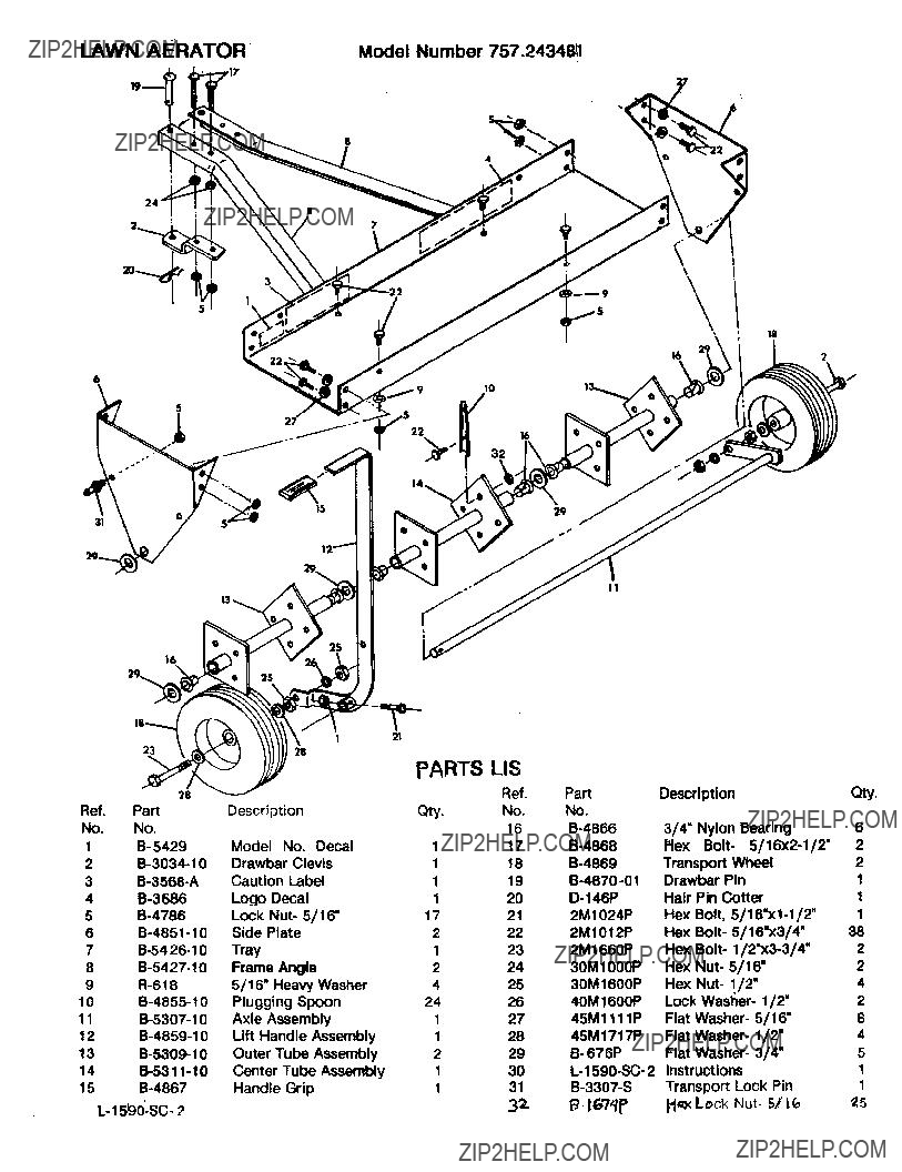
LAWN AI RATOR
Model Number 757.24348,_
$
4
\
16
29_
18
10
22 _16
II
25
23
28
Ref. Part
No. No.
1B- 5429
2
3
4
5
6
7
8
9
10
11
13
14
15