Owner???s Manual

 ??
??
AIR COMPRESSOR
1HP
Oil Lubricated
Model No. 921.153120
Sears, Roebuck and Co., Hoffman Estates, IL 60179 U.S.A.
www.sears.com
08/11/2006
Part No. E102346
Owner???s Manual
??
AIR COMPRESSOR
1HP
Oil Lubricated
Model No. 921.153120
Sears, Roebuck and Co., Hoffman Estates, IL 60179 U.S.A.
www.sears.com
08/11/2006
Part No. E102346
Page
Warranty . . . . . . . . . . . . . . . . . . . . . . . . . . . . . . . . . . . . . . . . . . . . . . . . . . . . . . . . . . . . . . See Below
Safety Symbols . . . . . . . . . . . . . . . . . . . . . . . . . . . . . . . . . . . . . . . . . . . . . . . . . . . . . . . . . . 1 Important Safety Instructions & Guidelines . . . . . . . . . . . . . . . . . . . . . . . . . . . . . . . . . . . . . 1 Specifications . . . . . . . . . . . . . . . . . . . . . . . . . . . . . . . . . . . . . . . . . . . . . . . . . . . . . . . . . . . . 2 Glossary . . . . . . . . . . . . . . . . . . . . . . . . . . . . . . . . . . . . . . . . . . . . . . . . . . . . . . . . . . . . . . . . 2 Duty Cycle . . . . . . . . . . . . . . . . . . . . . . . . . . . . . . . . . . . . . . . . . . . . . . . . . . . . . . . . . . . . . . 2 Parts & Features . . . . . . . . . . . . . . . . . . . . . . . . . . . . . . . . . . . . . . . . . . . . . . . . . . . . . . . . . 3 Installation & Assembly . . . . . . . . . . . . . . . . . . . . . . . . . . . . . . . . . . . . . . . . . . . . . . . . . . . . 4 Operating Procedures . . . . . . . . . . . . . . . . . . . . . . . . . . . . . . . . . . . . . . . . . . . . . . . . . . . . . 5 Detaching Unit from Dolly . . . . . . . . . . . . . . . . . . . . . . . . . . . . . . . . . . . . . . . . . . . . . . . . . . 6 Maintenance. . . . . . . . . . . . . . . . . . . . . . . . . . . . . . . . . . . . . . . . . . . . . . . . . . . . . . . . . . . . . 6 Storage . . . . . . . . . . . . . . . . . . . . . . . . . . . . . . . . . . . . . . . . . . . . . . . . . . . . . . . . . . . . . . . . 6 Troubleshooting Guide . . . . . . . . . . . . . . . . . . . . . . . . . . . . . . . . . . . . . . . . . . . . . . . . . . . . . 7 Exploded View . . . . . . . . . . . . . . . . . . . . . . . . . . . . . . . . . . . . . . . . . . . . . . . . . . . . . . . . . . . 8 Parts List . . . . . . . . . . . . . . . . . . . . . . . . . . . . . . . . . . . . . . . . . . . . . . . . . . . . . . . . . . . . . . . 9 Espa??ol . . . . . . . . . . . . . . . . . . . . . . . . . . . . . . . . . . . . . . . . . . . . . . . . . . . . . . . . . . . . . . . . 10
ONE YEAR FULL WARRANTY ON CRAFTSMAN AIR COMPRESSOR
If this Craftsman Air Compressor fails due to manufacturer???s defects in material or workmanship within one year of the date of purchase, RETURN IT TO THE NEAREST SEARS STORE OR SERVICE CENTER IN THE UNITED STATES and it will be replaced or repaired (at our option), free of charge.
If this Air Compressor is used for commercial or rental purposes, this warranty applies for only 90 days from the date of purchase. This warranty gives you specific legal rights and you may also have other rights which vary from state to state.
Sears, Roebuck and Co., Dept. 817WA,
Hoffman Estates, IL 60179

Safety Symbols
The information listed below should be read and understood by the operator. This information is given to protect the user while operating and storing the air compressor. We utilize the symbols below to allow the reader to recognize important information about their safety.
Important Safety Instructions and Guidelines
??? Save all instructions
 WARNING
WARNING: This product contains one or more chemicals known to the State of California to cause cancer and birth defects or other reproductive harm.
Wash hands after handling.
Improper operation or maintenance of this product could result in serious injury and/or property damage. Read and understand all of the warnings and safety instructions provided before using this equipment.
1

Important Safety Instructions & Guidelines
Risk of Bursting Always drain the air compressor tank daily or after each use. If the tank develops a leak, then replace the air compressor. Never use the air compressor after a leak has been found or try to make any modifications to the tank. Never modify the air compressor???s factory settings which control the tank pressure or any other function.
Specifications
Pump . . . . . . . . . . . . . . . . . . . . . . . . . .
Air Tank Capacity . . . . . . . . . . . . . . . . . . . . . . . . . 2 Gallons
Glossary
CFM: Cubic feet per minute.
SCFM: Standard cubic feet per minute; a unit of measure for air delivery.
PSIG: Pounds per square inch gauge; a unit of measure for pressure.
ASME: American Society of Mechanical Engineers.
California Code: Unit may comply with California Code 462 (l) (2)/ (M) (2).
start to refill the tank when the pressure drops below the prescribed minimum.
Code Certification: Products that bear one or more of the following marks: UL, ULc, ETL, CSA, have been evaluated by
Duty Cycle
This is a 50% duty cycle air compressor. Do not run the air compressor more than 30 minutes of one hour. Doing so could damage the air compressor.
2

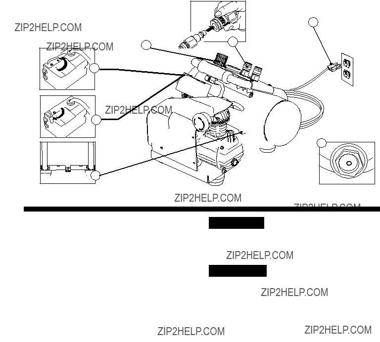
Parts & Features
See figures below for reference.
Check Valve
When the pump is not in operation the valve closes to retain air pressure inside the tank. An internal component.
Quick Connect
Offers a quick release feature for attaching and removing the air hose.
Regulator Gauge
Indicates the outgoing air pressure to the tool and is controlled by the regulator.
Regulator
The air pressure coming from the air tank is controlled by the regulator. To increase the pressure turn the knob clockwise and to decrease the pressure turn the knob counterclockwise.
Pressure Switch
This controls the power to the motor and also the
Tank Safety Valve
Used to allow excess tank pressure to escape into the atmosphere. This valve should only open when the tank pressure is above the maximum rated pressure.
Pressure Relief Valve
The pressure relief valve located on the side of the pressure switch, is designed to automatically release compressed air when the air compressor reaches
Pressure Relief Tube
Air Intake Filter
Provides clean air to the pump and must always be kept free of debris. Check on a daily basis or before each use.
Tank Drain Valve
Used to drain condensation from the air tank. Located at bottom of tank.
Tank Pressure Gauge
Indicates the reserve air pressure in the tank.
Outlet Tube
Oil Fill Cap
Oil Sight Gauge
3
Installation & Assembly
 WARNING
The air compressor should be turned off, unplugged from the power source, the air bled from the tank and the unit allowed time to cool before any maintenance is performed. Personal injuries could occur from moving parts, electrical sources, compressed air or hot surfaces. The quick connect assembly must be attached before use. Failure to assemble correctly could result in leaks and possible injury. If unsure of assembly instructions or you experience difficulty in the assembly please call your local service department for further instruction.
Assembly
1. Remove air compressor, oil bottle, intake filter, manual and accessories from the styrofoam.
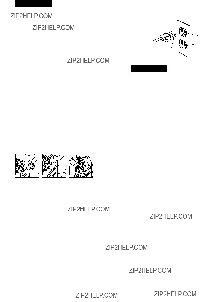
2. Remove the plastic plug from the compressor intake port. (see diagram below)
3. Install the filter in the compressor intake port.
(see diagram below)
4. Remove the oil fill cap from the crankcase and fill until the oil reaches the top of the red dot in the sight glass. Oil capacity is 3 oz. (see below) Use
5. Replace the oil cap.
6. Attach the handle to the frame with the saddle bolts from the outside of the handle and the knobs on the inside.
Getting Started - Location of the Air Compressor
The air compressor should always be located in a clean, dry and well ventilated environment. The unit should have at minimum, 12 inches of space on each side. The air filter intake should be free of any debris or obstructions. Check the air filter on a daily basis to make sure it is clean and in working order.
Grounding Instructions
This product should be grounded. In the event of an electrical short circuit, grounding reduces the risk of electric shock by providing an escape wire for the electric current.
This product is equipped with a cord having a grounding wire with an appropriate grounding plug. (See the figure at top right corner.) The plug must be plugged into an outlet that is properly installed and grounded in accordance with all local codes and ordinances. Check with a qualified
electrician or service personnel if these instructions are not completely understood or if in doubt as to whether the tool is properly grounded.
Plug
Grounded
Outlet
Grounding Pin
 WARNING
Improper installation of the grounding plug will result in a risk of electric shock. If repair or replacement of the cord or plug is necessary, do not connect the grounding wire to either flat blade terminal. The wire with insulation having an outer surface that is green with or without yellow stripes is the grounding wire. Check with a qualified electrician or serviceman if the grounding instructions are not completely understood, or if in doubt as to whether the product is properly grounded. Do not modify the plug provided.
If it will not fit the outlet, have the proper outlet installed by a qualified electrician.
This product is for use on a circuit having a nominal rating of 120 volts and is
Extension Cords
Use only a
Break In Procedures
No break in procedure is required by the user.
This product is factory tested to ensure proper operation and performance.
4
Operating Procedures
Daily
1. Set the
accessories/tools being used for damage or obstruction. If any of these mentioned items are in need of repair/ replacement, contact your local authorized service dealer before use.
3. Close the drain valve.
4. Check the oil level of the pump.
5. Connect the air hose to the quick connect socket on the regulator assembly by inserting the quick connect plug on the air hose into the quick connect socket. The quick connect socket collar will snap forward and lock the plug into place providing an air tight seal between the socket and plug. To release the air hose push the collar back on the quick connect socket.
6.Plug the power cord into the proper receptacle.
7.Turn the
8.Adjust the regulator to a PSI setting that is needed for your application and be sure it is within the safety standards required to perform the task. If using a pneumatic tool, the manufacturer should have recommendations in the manual for that particular tool on operating PSI settings.
9.The air compressor is now ready for use. The following inflation and cleaning accessories packaged with this unit should only be operated at maximum pressure
of 90PSI: blow gun,
 ?????????
????????????
???
7
?????????
1


 4
4

 3
3
Daily
1. Set the
3. Set the outlet pressure to zero on the regulator.
4. Remove any air tools or accessories. When draining the tank, always use ear and eye protection. Drain the tank in a suitable location; condensation will be present in most cases of draining.
5. Open the drain valve allowing air to bleed from the tank. After all of the air has bled from the tank, close the drain valve to prevent debris buildup in the valve.
 CAUTION
When draining the tank, always use ear and eye protection. Drain the tank in a suitable location; condensation will be present in most cases of draining.
 WARNING
Water that remains in the tank during storage will corrode and weaken the air tank which could cause the tank to rupture. To avoid serious injury, be sure to drain the tank after each use or daily.
5

Maintenance
NOTE: Any service procedure not covered in the maintenance schedule should be performed by qualified service personnel.
 WARNING
The air compressor should be turned off, unplugged from the power source, air bled from the tank and allowed time to cool before any maintenance is performed.
 CAUTION
To ensure efficient operation and longer life of the air compressor unit, a routine maintenance schedule should be followed. The following schedule is geared toward a consumer whose compressor is used in a normal working environment on a daily basis.
Storage
For storing the air compressor, be sure to do the following:
1.Turn the unit off and unplug the power cord from the receptacle.
2.Remove all air hoses, accessories, and air tools from the air compressor.
3.Perform the daily maintenance schedule.
4.Open the drain valve to bleed all air from the tank.
5.Close the drain valve.
6.Store the air compressor in a clean and dry location.
6

Troubleshooting Guide
WARNING The air compressor should be turned off and unplugged from the power source before any maintenance is performed as well as the air bled from the tank and the unit allowed time to cool. Personal injuries could occur from moving parts, electrical sources, compressed air, or hot surfaces.
Air leaks at the check valve or at the pressure relief valve.
A defective check valve results in a constant air leak at the pressure relief valve when there is pressure in the tank and the compressor is shut off. Drain the tank, then remove and clean or replace the check valve.
Air leak from safety valve.
Operate the safety valve manually by pulling on the ring. If the valve continues to leak when in the closed position, it should be replaced.
7

Air Compressor Model 15312
Parts List
8