GENERAL: Upon receipt of luminaire thoroughly inspect for any freight damage, which should be brought to the attention of the delivery carrier. Compare the catalog description listed on the packing slip
with the luminaire label on the housing to assure you have received the correct merchandise.
SAFETY: This luminaire must be wired in accordance with the national electrical code and applicable codes and ordinance. Proper grounding is required to insure personal safety. Carefully observe grounding procedure. All work should be done by a qualified electrician.
WARNING: Make certain power is OFF before starting installation or attempting any maintenance.
WARNING: Risk of Electric Shock. Disconnect power at fuse or circuit breaker before installing or servicing.
WARNING: Risk of Burn. Disconnect power and allow luminaire to cool before changing lamp or handling luminaire.
WARNING: RISK OF FIRE! DO NOT mount on or near combustible materials.
FAILURE TO FOLLOW INSTRUCTIONS MAY RESULT IN SERIOUS INJURY OR
DEATH
TASK LIGHT FIELD KIT INSTALLATION: (Figure 1)
1.Note: Remove tamper proof screws first if luminaire includes (TR)
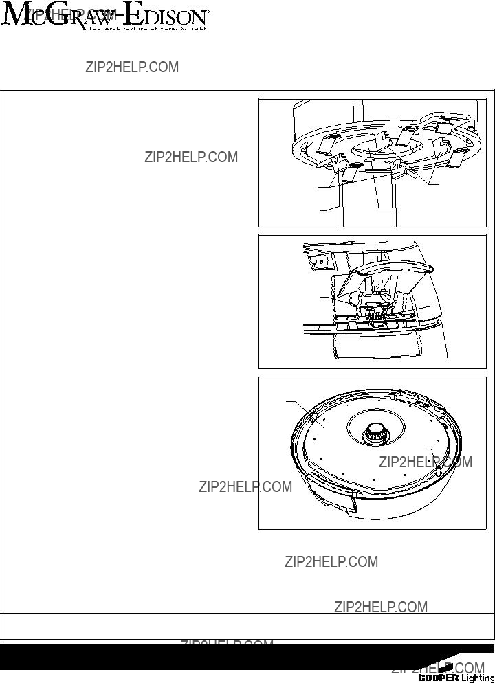
2.To release clasp lock on ???quick mount??? bracket, push handle inward and pull luminaire forward. (Figure 2). CAUTION: Do not let luminaire fall. Support luminaire while lowering off of
3.Remove luminaire hanging hook from quick mount plate (Figure 3 & 4). CAUTION: Support luminaire while removing.
CAUTION: DO NOT place luminaire directly with lens facing down; it may scratch or cause the lens to break. Place fixture with lens facing upright on stable work surface. SUGGESTION: Remove the lens completely in order to perform remaining of Task Light accessory installation.
Unlatch both latches. CAUTION: To avoid lens breakage, remove lens retainer if necessary (Figure 5). Remove the complete lens assembly and set aside to prevent damage. Take off upper reflector by loosening thumbscrews (See figure 6).
4.Reference dimensions as shown and mark housing if necessary (Figure 7 & 8).
5.Line up an adapter block and secure tightly if possible to aid in drilling (Figure 7 & 8).
CAUTION: DO NOT drill or damage other components inside luminaire. To avoid this from happening, remove them if necessary.
6.Drill center hole as specified and
7.Drill and tap the two outside holes as specified (Figure 7 & 8).
8.Install gasket and adapter block (with provided fasteners) (Figure 9).
9.Apply sealing compound on the threads of handle (provided by others).
10.Pull wires out of head through access in block. Screw the handle into adapter block. On inside of fixture, make connections and restrain with wire tie.
11.Aim the handle to a preferred position and lock it in position.
12.Aim task light head to a preferred position and tighten
13.To install lamp, remove task light cover by twisting
14.
Figure 1
SCREW FOR LATCH

SCREW FOR HANDLE
LATCH
Figure 2
TO REMOVE
HANDLE
PULL
PUSH
Figure 3
QUICK MOUNT
PLATE
HANGING
HOOK
LUMINAIRE
These instructions do not claim to cover all details or variations in the equipment, procedure, or process described, nor to provide directions for meeting every possible contingency during installation, operation or maintenance. When additional information is desired to satisfy a problem not covered sufficiently for user???s purpose, please contact your nearest representative.
NOTE: Specifications and dimensions subject to change without notice.
Customer First Center 1121 Highway 74 South Peachtree City, GA 30269 770.486.4800 FAX 770.486.4801 ADH080775

 LATCH
LATCH