HB1004
USER GUIDE
HB1004
USER GUIDE

. . . . . . . . . . . . . . . . . . . . . . . . . . . . . .
NOTICE
The information in this publication is subject to change without notice.
COMPAQ COMPUTER CORPORATION SHALL NOT BE LIABLE FOR TECHNICAL OR
EDITORIAL ERRORS OR OMISSIONS CONTAINED HEREIN, NOR FOR INCIDENTAL OR
CONSEQUENTIAL DAMAGES RESULTING FROM THE FURNISHING, PERFORMANCE, OR
USE OF THIS MATERIAL.
This publication contains information protected by copyright. No part of this publication may be photocopied or reproduced in any form without prior written consent from Compaq Computer Corporation.
The software described in this guide is furnished under a license agreement or non disclosure agreement.
The software may be used or copied only in accordance with the terms of the agreement.
Product names mentioned herein may be trademarks and/or registered trademarks of their respective companies.
?? 1998 Compaq Computer Corporation. All rights reserved. Printed in the U.S.A.
Compaq
Registered United States Patent and Trademark Office.
Compaq HB1004
First Edition (July 1998)
Part Number

. . . . . . . . . . . . . . . . . . . . . . . . . . . . . .
v
Contents
Chapter 1
Overview
Chapter 2
Installation
Chapter 3
Setup and Configuration
Compaq HB1004
. . . . . . . . . . . . . . . . . . . . . . . . . . . . . .

. . . . . . . . . . . . . . . . . . . . . . . . . . . . . .
vii
Appendix C
Certification and Compliance
Compaq HB1004

. . . . . . . . . . . . . . . . . . . . . . . . . . . . . .
Chapter 1
Overview
The Compaq HB1004
The hub supports both
Features
QFour
QIEEE 802.3 compliant
QProvides one DB9 connector RS232 port for
QOne port is selectable to provide either MDI or
QSupports automatic polarity detection and correction, permitting automatic recovery due to wiring errors
QAutomatically
QAutomatically adapts to a wide range of power sources
QCan be mounted on a desktop or in a standard 19??? rack
QIncludes a comprehensive LED indicator panel for reporting network activity, unit configuration, and problem diagnosis
QSNMP support including
MIB
QSupports FlashROM on board for easily updating the microcode using TFTP or the Compaq HB1004 System Configuration Program running on a PC
Compaq HB1004
. . . . . . . . . . . . . . . . . . . . . . . . . . . . . .
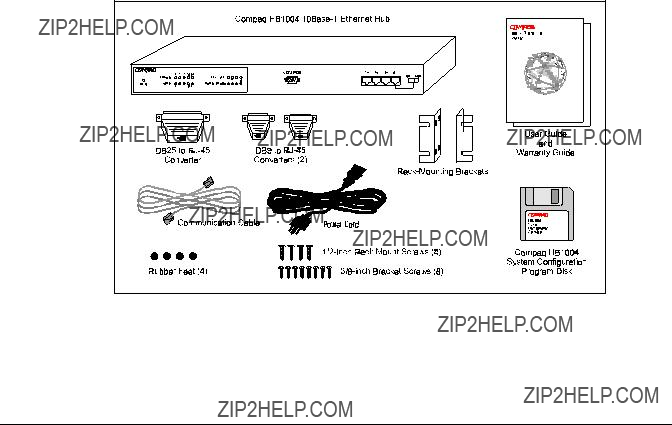
Package Contents
Before you start to install the hub, verify that this package contains the following items:
QCompaq HB1004
QCommunication cable
QAdapter connectors
QPower cord
Q
QFour
QCompaq HB1004 System Configuration Program diskette
QCompaq HB1004
. . . . . . . . . . . . . . . . . . . . . . . . . . . . . .
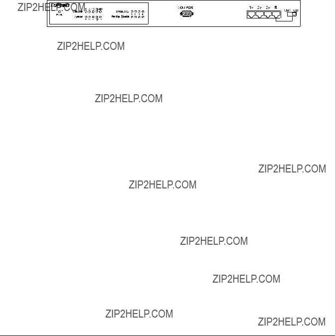
Hub Components
This section provides an overview of the Compaq HB1004 hub???s components including the LED indicators,
Figure
The hub???s four
Serial COM Port
The HB1004 hub contains a serial COM port that uses a male DB9 connector with a standard AT pinout. You can use this port to connect to a workstation for
LED Indicators
The LED panel of the hub helps you monitor the hub???s operation. When you power on the hub, it performs a
Compaq HB1004

. . . . . . . . . . . . . . . . . . . . . . . . . . . . . .
Unit LEDs
The
Table
Hub LED Conditions and Descriptions

. . . . . . . . . . . . . . . . . . . . . . . . . . . . . .
Port LEDs
There are two LEDs for each port to indicate link/activity and partition/disable on the ports.
Table
Port LED Conditions and Descriptions
The
Compaq HB1004
. . . . . . . . . . . . . . . . . . . . . . . . . . . . . .
Chapter 2
Installation
This chapter provides information to help you prepare for and install the hub and connect the hub to the network.
Mounting the Hub
You can place this hub directly on a desktop or mount it in a rack. Before you start installing the hub, make sure you can provide the right operating environment, including power requirements, sufficient physical space, and proximity to other network devices you want to connect. Verify the following installation requirements:
QPower requirements: 100 to 240 VAC (+/- 10%) at 50 to 60 Hz (+/- 3 Hz). The hub???s power supply automatically adjusts to the input voltage.
QThe hub should be located in a cool, dry place with at least 10 cm (4 in.) of space at the front and back for ventilation.
QPlace the hub out of direct sunlight and away from heat sources or areas with a high amount of electromagnetic interference.
QIf you intend to mount the hub in a rack, make sure you have all the necessary mounting screws, brackets, and tools.
QCheck if network cables and connectors needed for installation are available.
Mounting the Hub on a Flat Surface
This hub can be placed anywhere there is enough flat space, such as on a table or desktop.
1.Stick the
2.Place the hub on a firm, flat surface.
3.Be sure you allow at least 2 inches (5 cm) on each side and 4 inches (10 cm) at the back of the hub for proper airflow.
Compaq HB1004

. . . . . . . . . . . . . . . . . . . . . . . . . . . . . .
Mounting the Hub in a Rack
To mount the hub in a rack, follow these steps:
1.Use a standard EIA 19 inch rack
2.Use the brackets and screws supplied in the rack mounting kit
3.Use a
4.Position the hub in the rack by lining up the holes in the brackets with the appropriate holes on the rack, and then use the supplied screws to mount the hub in the rack

. . . . . . . . . . . . . . . . . . . . . . . . . . . . . .
Connecting the Hub System
The Compaq HB1004 hub has four
Making a Connection via an
You can connect any
1.Prepare the network devices you wish to network. Make sure you have installed
shielded or unshielded
2.Connect one end of the cable to the
Compaq HB1004

. . . . . . . . . . . . . . . . . . . . . . . . . . . . . .
WARNING: Do not plug a phone jack connector into any
This may damage the hub. Instead, use only
NOTES: 1. Make sure each
Making a Connection via the
1.To make a direct connection to a compatible hub or switch, use the
2.Prepare
NOTES: 1. To connect to another hub or switch, you may also attach to
2.When using Port 4 as an MDI port, set the port selection switch to MDI.
3.When connecting to another 10Mb/s hub, you can cascade up to four hubs, and use up to 100 meters (328 feet) of cable between each
Powering On the Hub
1.Plug the power cord into the power socket at the rear of the hub, and the other end into a power outlet (see Figure
2.Turn on the power switch on the back of the hub ( I = on; 0 = off).

. . . . . . . . . . . . . . . . . . . . . . . . . . . . . .
3.Check the LED marked PWR on the front panel to see if it is on. The unit will automatically select the setting that matches the connected input voltage. Therefore, no additional adjustments are necessary when connecting it to any input voltage within the specified range. See Appendix A for power requirements.
4.The hub performs a
Compaq HB1004
. . . . . . . . . . . . . . . . . . . . . . . . . . . . . .
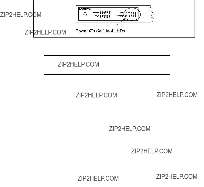
Diagnostic Tests
After power on, the hub automatically performs a diagnostic
The system tests each component one at a time. At the completion of the test, if no diagnostic LEDs are lit, then all components passed the test. If a component fails the test, the corresponding LED will continue blinking. The following table identifies the component that corresponds to each diagnostic test LED.
Figure
Table
LED Diagnostic Test Functions
. . . . . . . . . . . . . . .
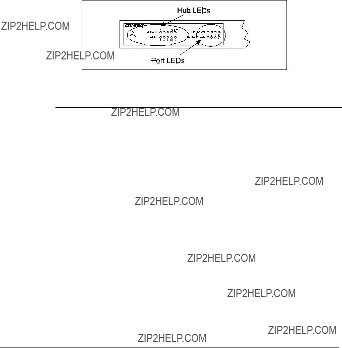
Verifying Hub and Port Status
. . . . . . . . . . . . . . .
After the hub completes the POST, you can check hub activity and each connection by comparing the indicators with Table
Figure
Table
Compaq HB1004
. . . . . . . . . . . . . . . . . . . . . . . . . . . . . .
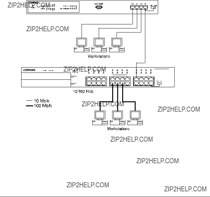
Applications
This hub is not only designed to provide network access for 10Mb/s connections, but also to provide options in setting up network connections. It can be used as a simple
Figure

. . . . . . . . . . . . . . . . . . . . . . . . . . . . . .
Chapter 3
Setup and Configuration
Preparing for Configuration
Management
There are two methods for configuring the Compaq HB1004 - using the
Q
Q
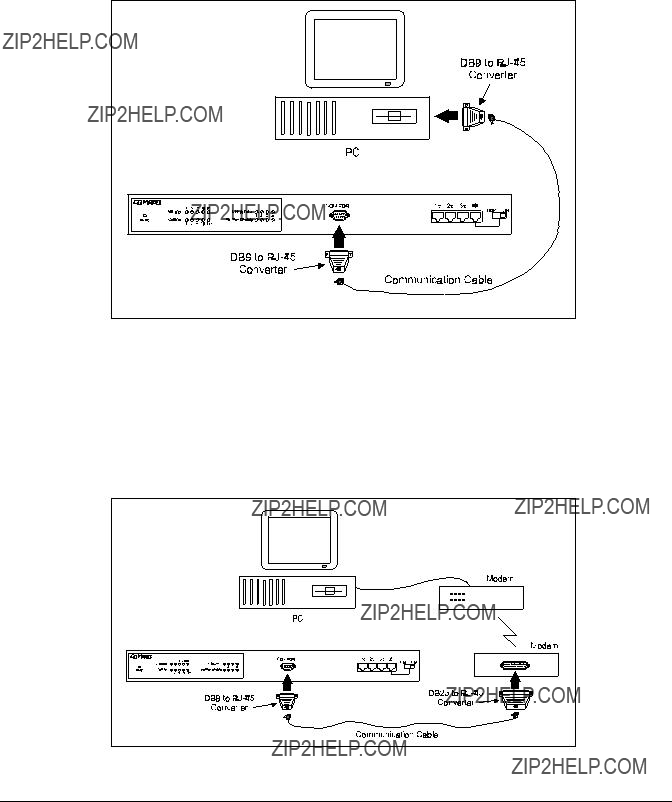
Onsite Connection
Attach a PC to the serial port on the hub. Use the communication cable (and DB9 to
NOTE: Some PCs may have a 25 pin serial port. For these PCs use the DB25 to
Compaq HB1004
. . . . . . . . . . . . . . . . . . . . . . . . . . . . . .
Modem Connection
Connect the COM port on the hub to the serial port on the modem. Use the communications cable provided with the hub and DB9/25 to
. . . . . . . . . . . . . . . . . . . . . . . . . . . . . .
You can configure and manage the hub through the network
Starting the Configuration Program
To open the Compaq HB1004 System Configuration Program, do the following:
1.Determine which operating system you are using and follow the proper instructions to start the HB1004 System Configuration Program.
To start the Compaq HB1004 System Configuration Program from
1.Insert the Compaq HB1004 Configuration Program diskette into the floppy disk drive
2.At the command prompt, type A:\HB1004CP for Drive A or
B:\HB1004CP for Drive B
3.Press ENTER and the program will start by opening the communication dialog box shown in Figure
NOTE: The Compaq HB1004 System Configuration Program allows selection of COM Ports 1, 2, 3 or 4 and assumes the normal default IRQ for the appropriate port (i.e. COM1 is IRQ4, COM2 is IRQ3, COM3 is IRQ4 and COM4 is IRQ3). If your communication port is configured differently, it is necessary to specify the correct IRQ for that port. If this is the case, type:
A:\HB1004CP /i[irq#] or B:\HB1004CP /i[irq#]
at the command prompt.
Compaq HB1004

. . . . . . . . . . . . . . . . . . . . . . . . . . . . . .
To start the Compaq HB1004 System
Configuration Program from
Windows:
1.Insert the Compaq HB1004 Configuration Program diskette into the floppy disk drive
2.In File Manager or Program Manager, click File, then click Run
3.Type A:\HB1004CP for Drive A or B:\HB1004CP for Drive B in the Command Line box
4.Click the OK button to open the program and display the communication dialog box shown in Figure
NOTE: The Compaq HB1004 System Configuration Program allows selection of COM Ports 1, 2, 3 or 4 and assumes the normal default IRQ for the appropriate port (i.e. COM1 is IRQ4, COM2 is IRQ3, COM3 is IRQ4 and COM4 is IRQ3). If your communication port is configured differently, it is necessary to specify the correct IRQ for that port. If this is the case, type:
A:\HB1004CP /i[irq#] or B:\HB1004CP /i[irq#]
In the Command Line box.
To start the Compaq HB1004 System
Configuration Program from
Windows 95 or Windows 98:
1.Insert the Compaq HB1004 Configuration Program diskette into the floppy disk drive
2.Click the Start button in the lower left corner of the screen
3.Click Run...
4.Type A:\HB1004CP for Drive A or B:\HB1004CP for Drive B in the Open box
5.Click the OK button to open the program and display the communication dialog box shown in Figure

. . . . . . . . . . . . . . . . . . . . . . . . . . . . . .
NOTE: The Compaq HB1004 System Configuration Program allows selection of COM Ports 1, 2, 3 or 4 and assumes the normal default IRQ for the appropriate port (i.e. COM1 is IRQ4, COM2 is IRQ3, COM3 is IRQ4 and COM4 is IRQ3). If your communication port is configured differently, it is necessary to specify the correct IRQ for that port. If this is the case, type:
A:\HB1004CP /i[irq#] or B:\HB1004CP /i[irq#]
in the Open box.
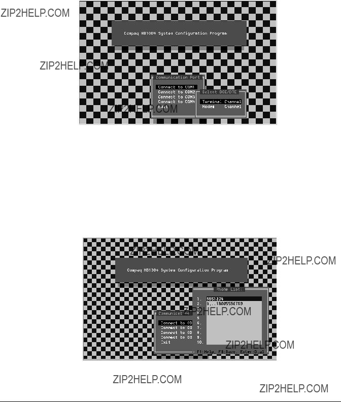
Figure
2. Using arrow keys, select the workstation???s communication port connected to the hub and press <Enter>. The DCE/DTE dialog box appears as shown in Figure
Compaq HB1004
. . . . . . . . . . . . . . . . . . . . . . . . . . . . . .
Figure
3.Select the appropriate option in the DCE/DTE dialog box:
Q Terminal Channel for local hookup, opens the Main Menu as shown in Figure
Q Modem Channel for remote connection via modems.
If you are using a modem connection, select Modem Channel to open the Phone List menu as shown in Figure
Figure

. . . . . . . . . . . . . . . . . . . . . . . . . . . . . .
Once the connection is established, the Main Menu for
Figure
4. Select any of the displayed menu items as described in the following section. Table
Compaq HB1004 System
Configuration
The Compaq HB1004 provides a proprietary,
Compaq HB1004

. . . . . . . . . . . . . . . . . . . . . . . . . . . . . .
Common Menu Functions
Many of the HB1004 System Configuration Program sub menus have common keys for navigating through the menus and setting menu options. Table

. . . . . . . . . . . . . . . . . . . . . . . . . . . . . .
System Configuration Settings
The HB1004 hub maintains three sets of configuration settings:
QCurrent configuration settings
QLast Saved configuration settings
QFactory Default configuration settings
The hub always operates using the Current configuration settings. Any changes you make to the hub???s configuration are kept as the Current configuration settings. When you exit from the configuration program those changes are not lost, even if you do not save them. Current configuration settings will remain in place until you change them again.
Once you save a configuration it is loaded into the Last Saved configuration settings. You can return to these settings at any time by selecting Reset Configuration from the Main Menu. At that time the Last Saved configuration becomes the Current configuration.
Compaq HB1004
. . . . . . . . . . . . . . . . . . . . . . . . . . . . . .
The Factory Default configuration settings never change and are always available to apply to the hub. When you select Factory Setting from the Main Menu the Factory Default configuration is loaded into the Current configuration. See Table
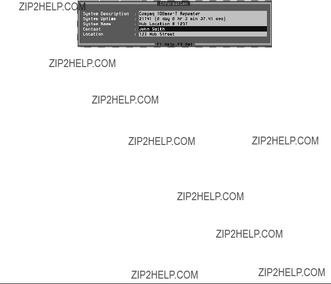
Displaying System Information
Use the Information command to display and modify system information about the hub, or for quick system identification. View a description of the system:
Figure
QSystem Description ??? Identifies the hub
QSystem Uptime - Length of time the management agent has been running
QSystem Name ???
QContact - Contact person for the system
QLocation - Specifies the area or location where the system resides
. . . . . . . . . . . . . . . . . . . . . . . . . . . . . .
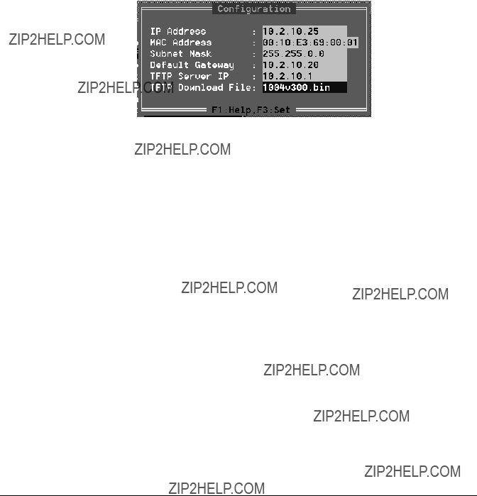
Changing System Configuration
Use the Configuration command from the Main Menu to modify current values for the following parameters:
Figure
QIP Address - IP address of the HB1004 agent. The agent runs the SNMP protocol over the UDP/IP transport protocol. In this environment, all systems on the Internet, such as network interconnection devices are assigned an IP address.
QMAC Address - Hardware address of the agent. The MAC address can also be found on a sticker on the front panel of the hub above the COM port.
QSubnet Mask - Subnet mask of the agent you???ve selected. This mask identifies the host address bits used for routing to specific subnets.
QDefault Gateway - Default gateway used in passing trap messages from the hub agent to the management station.
QTFTP Server IP ??? Sets the TFTP server IP address.
Q
Compaq HB1004

. . . . . . . . . . . . . . . . . . . . . . . . . . . . . .
Assigning Trap Managers
Use the Trap Managers command from the Main Menu to modify current values for the following parameters:
Figure
QSNMP Community Names - The community strings authorized for trap management access. All community strings used for IP Trap Managers must be listed in this table.
???Community Name - A community entry authorized for trap management access.
???Access Management - access is restricted to
???Status - The status of the current entry can be set to VALID or
INVALID.
QIP Trap Managers - IP management stations selected to receive trap messages from the HB1004 agent.
???IP Address - IP address of the management station.
???Community Name - The community string required for trap management access.
???Status - The status of the current entry can be set to VALID or
INVALID.
. . . . . . . . . . . . . . . . . . . . . . . . . . . . . .
Configuring Port Parameters
Use the Port Control command to configure the ports. This menu provides a brief description of the hub, and also allows you to enable/disable any port on the hub.
Figure
QPort Identifier - Numeric identifier 1 to 4.
QName -
QType - Connection type is
QStatus - Any port may be ENABLED or DISABLED.
QPart - Indicates if the port is partitioned.
QLink State - Indicates if the port has a valid connection to an external device.
Network Performance
The Network Status screen displays statistics for each of the hub ports. The last line shows total statistics for the hub and is the sum of all of the port statistics.
Figure
Compaq HB1004

. . . . . . . . . . . . . . . . . . . . . . . . . . . . . .
QFrames - Number of frames passing through this port or hub.
QBytes - Number of bytes passing through this port or hub.
QCollisions - Number of simultaneous node transmissions detected by this port or hub.
QAlignment Errors - Number of
QCRC Errors - Number of Ethernet Cyclic Redundancy Code errors detected by this port or hub.
QTotal Errors - Total number of errors, including CRC, alignment, FramesTooLong, ShortEvents, LateEvents, Jabber, and DataRateMismatches detected on this port or hub.
NOTE: The values displayed have been accumulated since the last system reboot or counter reset.
Downloading System Software
Use the Download command from the Main Menu to load available software updates into the agent???s flash ROM. The download file should be a .bin file; otherwise the agent will not accept it. Also, the Timeout and Retry fields must have a
Figure
Invoking this command brings up the Download dialog box. When all entries are confirmed, the display will change to show the progress of the download process. After downloading the new software, the agent will automatically restart. The following describes each entry in the dialog box:
QTimeout - Time to wait for a response.

. . . . . . . . . . . . . . . . . . . . . . . . . . . . . .
QRetry - Number of attempts to make contact.
QFilename - The *.bin file to download.
QTransferred Block - Current number of data block being transferred.
QTotal Blocks - Total number of blocks to transfer.
Restarting the Agent
Use the Restart command from the Main Menu to reset the agent. LEDs on the agent will light up sequentially as it executes the initialization test. This will also reset the statistics counter to 0 (zero).
Reverting Configuration to Factory Settings
Use the Factory Settings command from the Main Menu to change all configuration settings back to the factory defaults. See Table
Saving a New Configuration
The Save Configuration option saves any changes you have made to the hub???s configuration. The hub will use the new configuration each time it boots up until you change it again.
Resetting the Configuration
The Reset Configuration option returns the hub to the last saved configuration. See Page
Help
Use the Help option to get a brief description of each of the Main Menu options.
Compaq HB1004

. . . . . . . . . . . . . . . . . . . . . . . . . . . . . .
Appendix A
Specifications
HB1004
QAccess Method - CSMA/CD, 10 Mbps
QStandards Conformance - IEEE 802.3
QCommunication Rate - 10 Mbps
QMedia Supported - 100?? Category 3, 4, or 5 UTP/STP
QNumber of Ports - 4
QIndicator Panel LEDs for monitoring power, utilization, collisions, partition/disable, link/activity
QDimensions - 440 x 171 x 43 mm (17.32 x 6.73 x 1.69 in)
QWeight - 2.42 kg (5.34 lb)
QInput Power - 100~240 VAC, 50/60 Hz
QPower Consumption ??? (typical) 13 Watts @ 240VAC
QHeat Dissipation ??? (typical) 44.4 BTU/hr @ 240VAC
QEnvironmental
???Temperature ??? Operating: 0??C to 40??C (32 to 104??F)
???Storage: 0??C to 60??C (32 to 140??F)
???Humidity ??? Operating/Storage: 5% to 95%
???Altitude ??? Operating: 0 to 3 km (0 to 10,000 ft)
???Storage: 0 to 9 km (0 to 30,000 ft)
QCertification CE Mark
QEmissions CISPR 22 Class A
QImmunity IEC
QSafety T??V/GS
Compaq HB1004

. . . . . . . . . . . . . . . . . . . . . . . . . . . . . .
Network Criteria
Q
Q
QTotal Network Span
???Single Hub 200 meters of
???
Management Support
QSystem Configuration
???
???
QManagement Agent ??? SNMP support including MIB II (RFC1213), repeater MIB (RFC1516), and Compaq private MIB.

. . . . . . . . . . . . . . . . . . . . . . . . . . . . . .
Appendix B
Troubleshooting
Diagnosing Hub Indicators
The hub can be easily monitored through panel LED indicators to assist the network manager in identifying problems. This section describes common problems you may encounter and possible solutions.
Table
Diagnosing Hub Indicators
Link indicator does not light up (green) after making a connection
Network interface (e.g., a network adapter card on the attached device), network cable, or hub port is defective
Verify that the hub and attached device are powered on. Be sure the cable is plugged into both the hub and attached device. Check the adapter on the attached device and cable connections for possible defects. See if your cable is functioning properly by using it for another port and attached device that displays valid indications when connected to the network. Replace the defective adapter or cable if necessary. Also verify that you have not exceeded specified limits for any attached media.
Compaq HB1004

. . . . . . . . . . . . . . . . . . . . . . . . . . . . . .
Power and Cooling Problems
If the power indicator does not turn on when the power cord is plugged in, you may have a problem with the power outlet, power cord, or internal power supply as explained in the previous section. However, if the unit powers off after running for a while, check for loose power connections, power losses or surges at the power outlet, and verify that the fan on back of the unit was unobstructed and running prior to shutdown. If you still cannot isolate the problem, then the internal power supply may be defective. In this case, contact Compaq Technical Support at
Installation
Verify that all system components have been properly installed. If one or more components appear to be malfunctioning (e.g., the power cord or network cabling), test them in an alternate environment where you are sure that all the other components are functioning properly.
Port and Cable Assignments

. . . . . . . . . . . . . . . . . . . . . . . . . . . . . .
Table
Twisted Pair Cable
Figure
S
C rossover
Figure
Compaq HB1004

. . . . . . . . . . . . . . . . . . . . . . . . . . . . . .
Using Diagnostic Mode
When you power up the HB1004 hub, the unit executes a
Figure
Configuration
Select Configuration to view and modify the hub configuration parameters. See Chapter 3 ???Changing System Configuration??? for an explanation of the entries in this screen shown in Figure
Figure

. . . . . . . . . . . . . . . . . . . . . . . . . . . . . .
Download
The Download option allows you to download software to the agent???s flash ROM. The Diagnostic Mode Download operation and screen is the same as for normal mode. See Chapter 3 ???Downloading System Software??? for information.
Factory Settings
This option allows you to reset all hub settings to the default factory configuration. The Diagnostic Mode Factory Settings operation and screen is the same as for normal mode.
Table
Factory Default Settings
Compaq HB1004
. . . . . . . . . . . . . . . . . . . . . . . . . . . . . .
Help
The Help option provides a brief description of the Diagnostic Mode Maim Menu options.
Exit
Exits the Diagnostic Mode and returns to DOS.
. . . . . . . . . . . . . . . . . . . . . . . . . . . . . .
Appendix C
Certification and Compliance
European Union (EU) Notice
Products with the CE Marking comply with both the EMC Directive (89/336/EEC) and the Low Voltage Directive (73/23/EEC) issued by the Commission of the European Community.
Compliance with these directives implies conformity to the following European Norms (in brackets are the equivalent international standards):
???EN55022 (CISPR 22) - Electromagnetic Interference
???
???EN60950 (IEC950) - Product Safety
CAUTION: Do not plug a phone jack connector in the
Safety Compliance
Wichtige Sicherheitshinweise (Germany)
1.Bitte lesen Sie diese Hinweise sorgf??ltig durch.
2.Heben Sie diese Anleitung f??r den sp??teren Gebrauch auf.
3.Vor jedem Reinigen ist das Ger??t vom Stromnetz zu trennen. Verwenden Sie keine Fl??ssigoder Aerosolreiniger. Am besten eignet sich ein angefeuchtetes Tuch zur Reinigung.
4.Die Netzanschlu?? steckdose soll n??he dem Ger??t angebracht und leicht zug??nglich sein.
5.Das Ger??t ist vor Feuchtigkeit zu sch??tzen.
6.Bei der Aufstellung des Ger??tes ist auf sicheren Stand zu achten. Ein Kippen oder Fallen k??nnte Besch??digungen hervorrufen.
Compaq HB1004

. . . . . . . . . . . . . . . . . . . . . . . . . . . . . .
7.Die Bel??ftungs??ffnungen dienen der Luftzirkulation, die das Ger??t vor ??berhitzung sch??tzt. Sorgen Sie daf??r, da?? diese ??ffnungen nicht abgedeckt werden.
8.Beachten Sie beim Anschlu?? an das Stromnetz die Anschlu??werte.
9.Verlegen Sie die Netzanschlu??leitung so, da?? niemand dar??ber fallen kann. Es sollte auch nichts auf der Leitung abgestellt werden.
10.Alle Hinweise und Warnungen, die sich am Ger??t befinden, sind zu beachten.
11.Wird das Ger??t ??ber einen l??ngeren Zeitraum nicht benutzt, sollten Sie es vom Stromnetz trennen. Somit wird im Falle einer ??berspannung eine Besch??digung vermieden.
12.Durch die L??ftungs??ffnungen d??rfen niemals Gegenst??nde oder Fl??ssigkeiten in das Ger??t gelangen. Dies k??nnte einen Brand bzw. elektrischen Schlag ausl??sen.
13.??ffnen sie niemals das Ger??t. Das Ger??t darf aus Gr??nden der elektrischen Sicherheit nur von authorisiertem Servicepersonal ge??ffnet werden.
14.Wenn folgende Situationen auftreten ist das Ger??t vom Stromnetz zu trennen und von einer qualifizierten Servicestelle zu ??berpr??fen:
a.Netzkabel oder Netzstecker sind besch??digt.
b.Fl??ssigkeit ist in das Ger??t eingedrungen.
c.Das Ger??t war Feuchtigkeit ausgesetzt.
d.Wenn das Ger??t nicht der Bedienungsanleitung entsprechend funktioniert oder Sie mit Hilfe dieser Anleitung keine Verbesserung erzielen.
e.Das Ger??t ist gefallen und/oder das Geh??use ist besch??digt.
f.Wenn das Ger??t deutliche Anzeichen eines Defektes aufweist.
15.Zum Netzanschlu?? dieses Ger??tes ist eine gepr??fte Leitung zu verwenden. F??r einen Nennstrom bis 6A und einem Ger??tegewicht gr????er 3kg ist eine Leitung nicht leichter als
Der arbeitsplatzbezogene Schalldruckpegel nach DIN 45 635 Teil 1000 betr??gt 70dB(A) oder weniger.

. . . . . . . . . . . . . . . . . . . . . . . . . . . . . .
Index
A
Access Management
Alignment Errors
C
Category 3
Check LED marked PWR
cable
Community Name
CRC
D
DB9 connector
E
EIA 19 inch rack
F
Factory default settings
File Manager
H
Hardware address
I
IEEE 802.3
IP
address
IRQ
J
Jack connector
L
LAN
LAN bandwidth
Last saved configuration
LED
indicators
Link state
M
MAC Address
Main Menu
Management software
station
MDI
port
port
slide switch
Compaq HB1004

. . . . . . . . . . . . . . . . . . . . . . . . . . . . . .
port
N
Network Status screen
O
Open box
P
Phone List menu
Pin serial port
Pinout
MDI
Port Identifier
Port RS232
Program Manager
R
port
S
Save Configuration option
SNMP
Community Names
software
SRAM
Subnet mask
Description
T
Terminal Channel
TFTP
download file
Trap management access
Trap messages
U
UDP/IP transport protocol
V
Ventilation
W
Warranty guide
Windows 95
Windows 98