StorageWorks by Compaq Modular SAN Array Fabric Switch 6
User Guide
Part Number
June 2002 (Second Edition)
This guide is designed to be used as
StorageWorks by Compaq Modular SAN Array Fabric Switch 6
User Guide
Part Number
June 2002 (Second Edition)
This guide is designed to be used as
?? 2002 Compaq Information Technologies Group, L.P.
Compaq, the Compaq logo, and StorageWorks are trademarks of Compaq Information Technologies Group, L.P. in the U.S. and/or other countries.
Microsoft,
Compaq shall not be liable for technical or editorial errors or omissions contained herein. The information in this document is provided ???as is??? without warranty of any kind and is subject to change without notice. The warranties for Compaq products are set forth in the express limited warranty statements accompanying such products. Nothing herein should be construed as constituting an additional warranty.
Modular SAN Array Fabric Switch 6 User Guide
June 2002 (Second Edition)
Part Number

Contents
Laser Precautions and Fibre Cables
Updating the Fabric Switch MSA Fabric Switch 6 Management Utility

About This Guide
This guide is designed to be used as
Intended Audience
This guide is intended for readers with a moderate level of SAN and system administration experience.
 Important Safety Information
Before installing this product, read the Important Safety Information document provided.
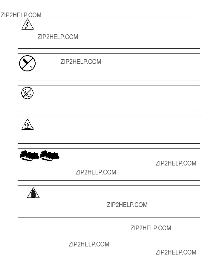
Symbols on Equipment
The following symbols may be placed on equipment to indicate the presence of potentially hazardous conditions:
WARNING: This symbol, in conjunction with any of the following symbols, indicates the presence of a potential hazard. The potential for injury exists if warnings are not observed. Consult your documentation for specific details.
About This Guide
This symbol indicates the presence of hazardous energy circuits or electric shock hazards. Refer all servicing to qualified personnel.
WARNING: To reduce the risk of injury from electric shock hazards, do not open this enclosure. Refer all maintenance, upgrades, and servicing to qualified personnel.
This symbol indicates the presence of electric shock hazards. The area contains no user or field serviceable parts. Do not open for any reason.
WARNING: To reduce the risk of injury from electric shock hazards, do not open this enclosure
This symbol on an
WARNING: To reduce the risk of electric shock, fire, or damage to the equipment, do not plug telephone or telecommunications connectors into this receptacle.
This symbol indicates the presence of a hot surface or hot component. If this surface is contacted, the potential for injury exists.
WARNING: To reduce the risk of injury from a hot component, allow the surface to cool before touching.
These symbols, on power supplies or systems, indicate that the equipment is supplied by multiple sources of power.
WARNING: To reduce the risk of injury from electric shock, remove all power cords to completely disconnect power from the system.
Weight in kg Weight in lb
This symbol indicates that the component exceeds the recommended weight for one individual to handle safely.
WARNING: To reduce the risk of personal injury or damage to the equipment, observe local occupational health and safety requirements and guidelines for manual material handling.
About This Guide
Rack Stability
WARNING: To reduce the risk of personal injury or damage to the equipment, be sure that:
???The leveling jacks are extended to the floor.
???The full weight of the rack rests on the leveling jacks.
???The stabilizing feet are attached to the rack if it is a
???The racks are coupled in
???Only one component is extended at a time. A rack may become unstable if more than one component is extended for any reason.
Symbols in Text
These symbols may be found in the text of this guide. They have the following meanings.
WARNING: Text set off in this manner indicates that failure to follow directions in the warning could result in bodily harm or loss of life.
CAUTION: Text set off in this manner indicates that failure to follow directions could result in damage to equipment or loss of information.
IMPORTANT: Text set off in this manner presents clarifying information or specific instructions.
NOTE: Text set off in this manner presents commentary, sidelights, or interesting points of information.
About This Guide
Text Conventions
This document uses the following conventions:
???Italic type is used for complete titles of published guides or variables. Variables include information that varies in system output, in command lines, and in command parameters in text.
???Bold type is used for emphasis, for onscreen interface components (window titles, menu names and selections, button and icon names, and so on), and for keyboard keys.
???Monospace typeface is used for command lines, code examples, screen displays, error messages, and user input.
???Sans serif typeface is used for uniform resource locators (URLs).
Related Documents
For additional information on the topics covered in this guide, refer to the following documentation:
???StorageWorks by Compaq Modular SAN Array 1000 User Guide, part number 230941
???StorageWorks by Compaq Modular SAN Array 1000 Installation Overview, part number 230935
Getting Help
If you have a problem and have exhausted the information in this guide, you can get further information and other help in the following locations.
About This Guide
HP Technical Support
In North America, call the HP Technical Support Phone Center at
Be sure to have the following information available before you call HP:
???Technical support registration number (if applicable)
???Product serial number
???Product model name and number
???Applicable error messages
???
???
???Operating system type and revision level
HP Website
The HP website has information on this product as well as the latest drivers and flash ROM images. You can access the HP website at www.hp.com.
HP Authorized Reseller
For the name of your nearest HP authorized reseller:
???In the United States, call
???In Canada, call
???Elsewhere, see the HP website for locations and telephone numbers.
1
Overview of the Switch
This guide provides specific information for installing and configuring the MSA Fabric Switch 6 and its component parts.
Table
WARNING: To reduce the risk of personal injury or damage to the equipment, refer to the user documentation supplied with the server and observe the appropriate safety precautions.
Overview of the Switch
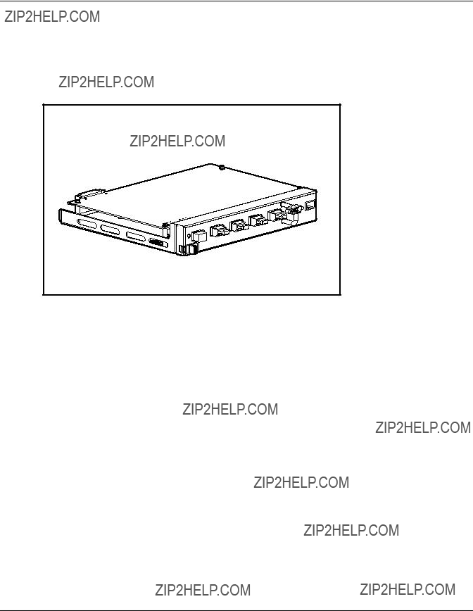
The MSA Fabric Switch 6
The MSA Fabric Switch 6 is an integrated
Figure

Overview of the Switch
Features
The MSA Fabric Switch 6 includes:
???A main board enclosing the 12 Gbps switching engine
???Microprocessor and other hardware logic to support the switch software agents
???MSA Fabric Switch 6 Management Utility
???Full Duplex Communications - A pair of nodes can simultaneously send and receive data for an aggregate of 2 Gbps
???Automatic Port Bypass - Improves SAN reliability by automatically bypassing errant ports
???Global Status Indicator (GSI)
???
???
???Null modem cable
???Five external 2/1 Gbps ports, 1 internal 2/1 Gbps port
???Auto switch between 1 and 2 Gbps
???Array Configuration
???Compaq Insight Manager
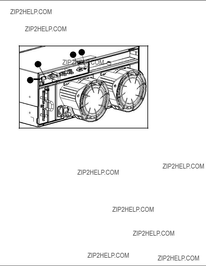
Overview of the Switch
Rear View of the Modular San Array 1000
Figure
Figure
Overview of the Switch
Installation
Before the MSA Fabric Switch 6 can communicate with
Ethernet
This connector is provided for management through Simple Network Management Protocol (SNMP). By default, the MSA Fabric Switch 6 is configured to use an IP address of 127.0.0.1. To change this IP address, use
This connector is provided for advanced configuration and management.
The MSA Fabric Switch 6 is designed to function directly out of its shipping container with no special configuration required. However, you have the ability to configure and monitor various aspects of the MSA Fabric Switch 6 by using
Overview of the Switch
The MSA Fabric Switch 6 is
When adding or replacing a switch, allow sufficient time to complete the
To power on the unit properly:
1.Power on the MSA1000.
On power up, the switch will run several POST tests and the GSI indicator will display changing patterns (refer to the section ???Reading the Global Service Indicator??? in Chapter 4, ???Troubleshooting???).
2.Power on I/O device(s).
3.Verify that the storage device(s) are visible to the host(s).
4.Start Applications.
Before the MSA Fabric Switch 6 can communicate with
2
Initial Configuration of the Switch
This chapter details the procedures used to initially configure the MSA Fabric Switch 6. Preliminary switch configuration includes entering the Ethernet and the SNMP settings.
Two configuration methods are available:
???Using the
???Using the Array Configuration
Initial Configuration of the Switch
Configuration Overview
When a switch is initially connected to a network, the network does not recognize it and does not know its IP address. Accessing the switch and entering the Ethernet and SNMP settings assigns the switch a location and makes it available to the network.
After the switch is accessible, additional parameters must be entered. These secondary configuration tasks can be performed from four different user interfaces, including the
The
The CLI of the switch provides access to extensive management and monitoring functions and is available directly through the serial port in the front of the switch or remotely through the switch???s Ethernet interface using telnet. During initial
The
The MSA Fabric Switch 6 Management Utility provides most of the functions available in the
Initial Configuration of the Switch
Using the
The
???The telnet interface is available only after the MSA Switch is completely booted. This means the results of the initialization tests are not viewable and if a reset is issued, the telnet connection is terminated.
???Users are unable to change the password over the telnet interface.
Another difference between using the serial port interface and telnet is that when using telnet, you can only get access to the switch after it has started up and has initialized its network parameters. Consequently, you must have a
Connecting a Terminal to the Switch
NOTE: This process uses a computer running on Microsoft Windows NT 4.0 or later. However, the switch can communicate with any operating system that utilizes a terminal emulator. If your computer uses another operating system, be sure that the baud rate, data bits, stop bits, parity, and terminal emulation are set for the selected serial port as specified in this procedure.
To directly connect a terminal to the MSA Switch:
1.Make sure there is power to the switch and attach a terminal or terminal emulator.
2.Connect a server serial port to the switch???s
3.Power on the server (if it is not already on).
4.Access the terminal emulator on the server. In Windows NT 4.0, select Start???Programs???Accessories???HyperTerminal
Initial Configuration of the Switch
5.Set up the properties for the terminal connection. In Windows NT 4.0:
a.
b.Enter a name for the connection in the New Connection dialog box, select an icon to represent the switch for future use, and click OK.
The Connect To dialog box is displayed.
6.From the Connect using
Table
7.Select File???Properties to show the connection properties dialog box. Select the Settings tab. From the Emulation
8.Power ON all peripheral device(s).
9.Wait at least ten seconds and power cycle the MSA1000. The switch sends a series of

Initial Configuration of the Switch
Logging in to the
Upon connection to the switch or completion of the
The default login variables assigned at the factory are:
Login: user
Password: ADMIN
To access the
1.At the Login prompt, enter user as the login variable.
>Login: user
2.At the password prompt, enter the assigned password.
>Password: ADMIN
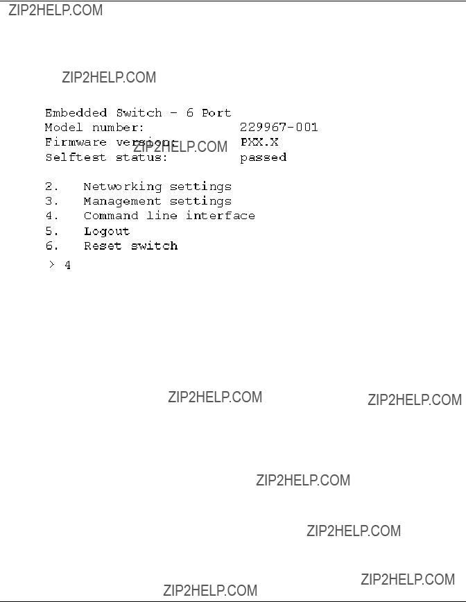
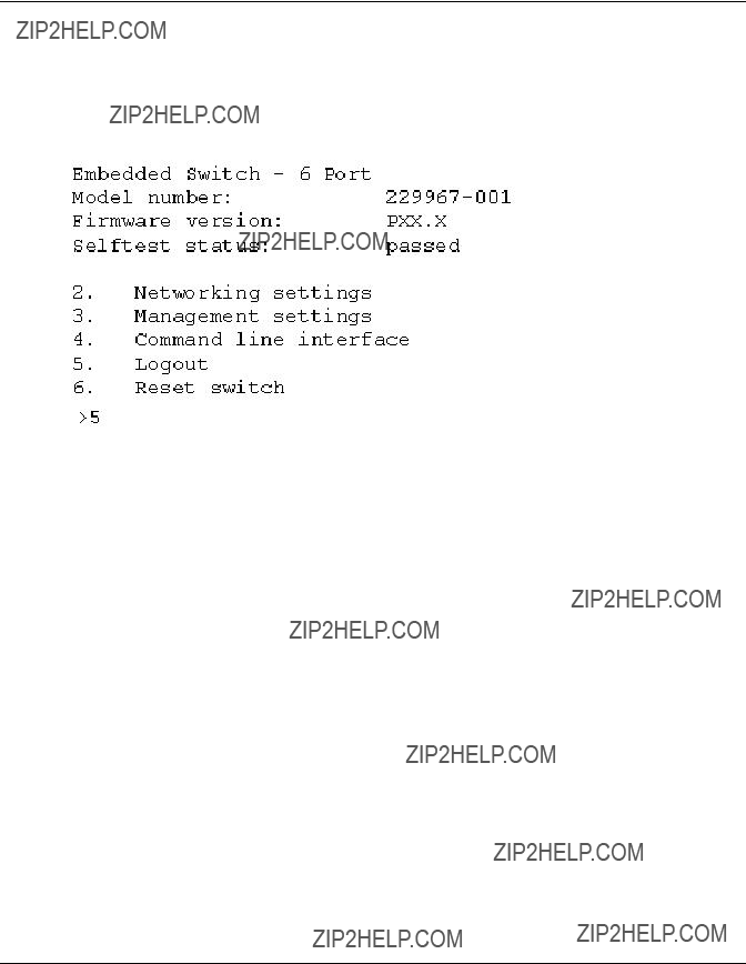
Upon successful login, the main menu is displayed. Figure
Figure
The main menu contains a brief summary of the status of the switch, including the model number, the firmware version, and whether it passed its
NOTE: If the

Initial Configuration of the Switch
Accessing Networking Parameters
Select option 2. Networking parameters to access the Network Parameter menu, which is shown Figure
The second, third, and fourth parameters are used to configure the Ethernet settings for the MSA Switch. All these parameters must be set appropriately for the site before the MSA Switch can be managed over the Ethernet and connected to using telnet.
Figure
Initial Configuration of the Switch
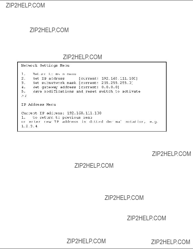
Setting the IP Address
Select option 2. Set IP address in the Network Parameters menu to call up the IP Address menu shown in the figure below. It displays the current IP address. The default (127.0.0.1) is set at the factory. This address should be changed to an IP address appropriate to your site. Check with the network administrator if uncertain of what this should be. Check with your network administrator before using the default address, as it is a special IP address used for testing purposes only.
Figure
Initial Configuration of the Switch
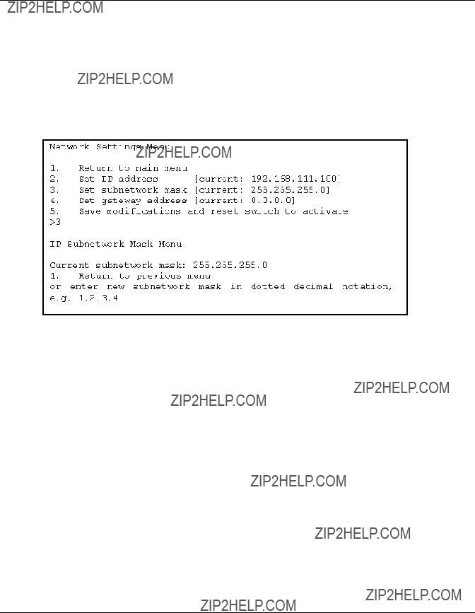
Setting the Subnetwork Mask
Select option 3. Set subnetwork mask in the Network Parameters menu to call up the Subnetwork Mask Menu. The default subnetworking mask is a Class C mask as shown in the figure below. This mask will work in many installations, as Class C IP networks are by far the most common. The best source of the correct mask is your local network administrator.
Figure
Initial Configuration of the Switch
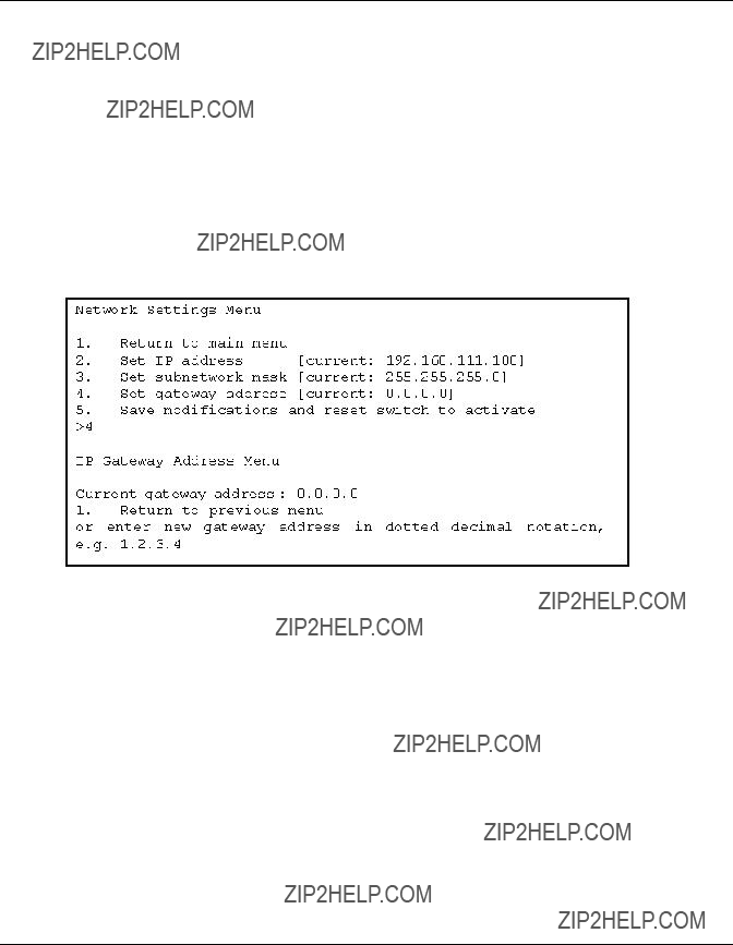
Setting the Gateway Address
Select option 4. Set gateway address in the Network Parameters menu to call up the Set Gateway Address menu, which is shown in Figure
The gateway is a computer or Ethernet router that connects your segment of the Ethernet to other segments. This is also true if using telnet to communicate with the MSA Fabric Switch 6 over the Ethernet from systems on other segments. In both of these cases, the MSA Fabric Switch 6 will need the IP address of the gateway system in order for it to function. Direct questions about gateways to your local network administrator.
Figure
Saving Modifications
Though a number of parameters may have been set in the Network Parameters menu, none are permanent until the Save modifications and reset switch to activate option is chosen. This saves the parameters in
Initial Configuration of the Switch
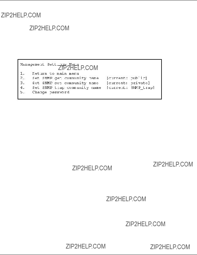
Accessing Management Parameters
Select option 3. Management settings in the main menu to call up the Management Settings Menu, which is shown in Figure
Unlike the Network Parameters menu, changes made in this menu become effective as soon as they are made. There is no need to reset the switch.
Figure
Options include:
1.Return to main menu allows the user to return to the main menu.
2.Set SNMP get community string calls up the SNMP Get Community Name menu. This allows the user to restore the default SNMP get community name or to enter a new SNMP get community name.
3.Set SNMP set community string calls up the SNMP Set Community Name menu. This allows the user to restore the default SNMP set community name or to enter a new SNMP set community name. The SNMP Set community string is the password that any SNMP client must use to write settings to the SNMP agent on the MSA Fabric Switch 6. This name can be any ASCII string desired. The factory default is ???private.???
4.Set SNMP trap community string calls up the SNMP Trap Community Name menu. The SNMP Trap community string is the password that any SNMP client must use to poll the SNMP agent on the MSA Fabric Switch 6 for SNMP traps. This name can be any desired ASCII string. The factory default is ???SNMP_trap.???
To change the SNMP Trap Community string, type the new name at the command prompt and press the Enter key.
Initial Configuration of the Switch
5. Change Password is used to enter a new password. There will be verification to test if this has been successfully completed or not. For security reasons, the password can only be changed through the serial port. It cannot be changed through a telnet connection over the Ethernet.
The password can be set to null (that is, a carriage return) or an alphanumeric password can be used with up to eight characters. The space cannot be part of the password as it is used to separate the first and second copies of the new password.
NOTE: If the new password is forgotten, contact your network administrator. You will need the unit???s serial number and Ethernet MAC address.
Accessing the CLI
Select option 4. Command line interface on the main menu, to call up the command line interface. This gives the user the ability to change parameters. These parameters should only be modified by a knowledgeable user in order to modify the MSA Switch operational parameters, to set up policies, as well as to troubleshoot problems.
The complete Command Line Interface is outlined in Appendix C, ???Command Line Interface.???
Exiting the
The user can log out of the MSA Switch by selecting option 5. Logout in the main menu. The original login prompt is redisplayed.
Resetting the Switch
Select option 6. Reset Switch in the main menu to reboot the switch. This should not be done in a haphazard manner as all Fibre Channel connections provided by the switch can be affected and any management data stored in the switch will be erased.

Initial Configuration of the Switch
Using the Array Configuration
When using the
In addition to accessing the
???Initial switch configuration
???Advanced switch configuration
As discussed previously, initial switch configuration includes setting the IP address, Subnet Mask, and Default Gateway of the switch (and the redundant switch, if installed). Until these Ethernet and SNMP parameters are entered, a Web Browser cannot find or connect to the switch.
Advanced switch configuration includes managing and monitoring ports, setting up zoning, and upgrading the switch firmware. Advanced configuration tasks are performed in using the MSA Fabric Switch 6 Management Utility. A link to this utility is provided in the
NOTE: The switch configuration utility Web link to the MSA Fabric Switch 6 Management Utility is present only if the selected controller supports this feature.
NOTE: In the following screen examples, the configuring server???s IP address is 10.100.100.14. One switch has an IP address of 10.100.100.10 and the other switch???s IP address is 10.100.100.11.

Initial Configuration of the Switch
Accessing the Switch Configuration Option of the
The
Figure
Figure
To start the
1.Select Compaq Array Configuration Utility XE.
The
Initial Configuration of the Switch
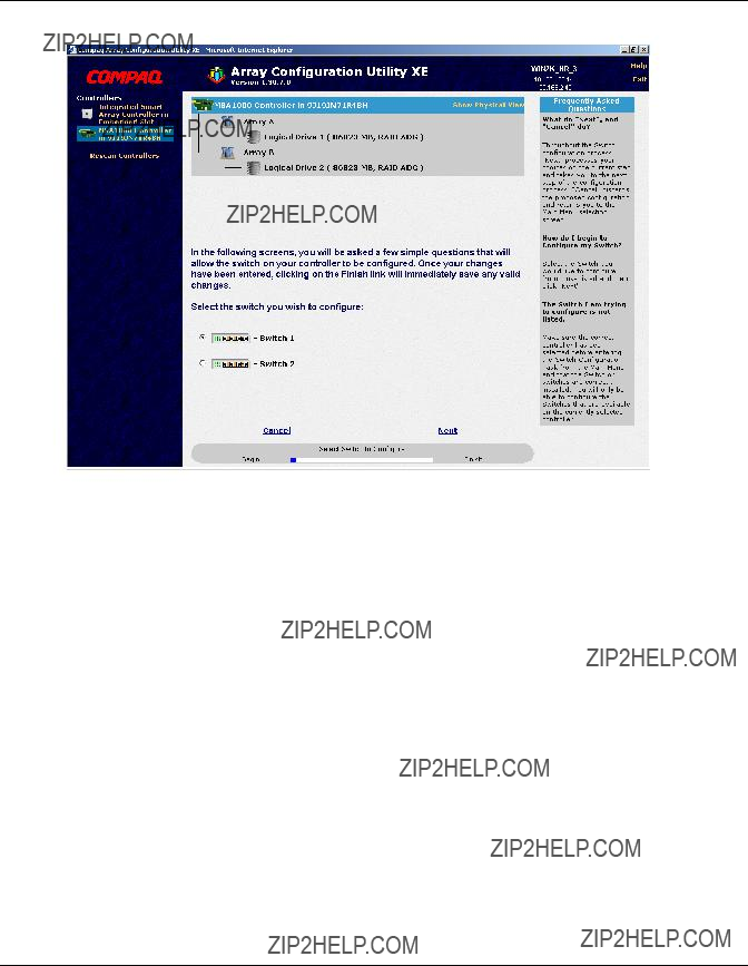
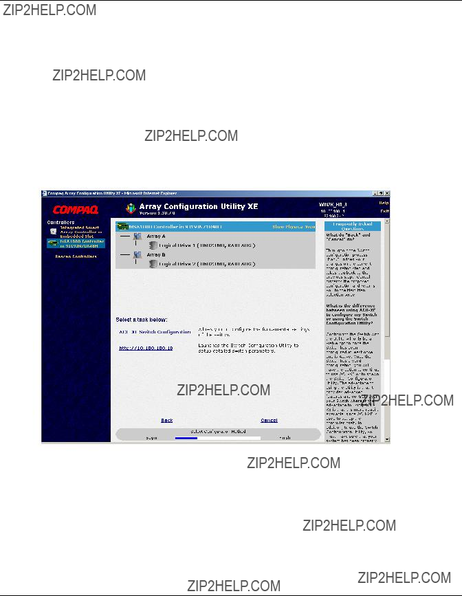
2.In the main
Three configuration methods are displayed at the bottom portion of the screen:
???Assisted Configuration is used to configure the controller.
???Advanced Configuration is used to configure the controller.
???Switch Configuration is used to configure the switch.
Figure
3.Select Switch Configuration.
All available switches detected by the
In the example shown in Figure
Initial Configuration of the Switch
Figure
4. Select a switch to configure.
Initial Configuration of the Switch
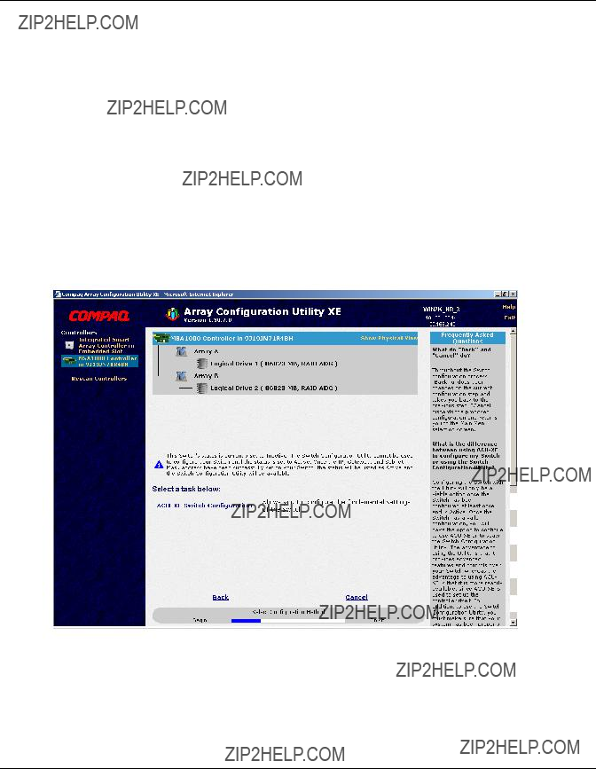
Initial Switch Configuration
After a switch is selected in the Switch Configuration screen, available configuration tasks for that switch are listed. See Figure
During the initial configuration of the switch, only one option is displayed. If the switch has already been configured and is active, additional tasks are displayed. These additional tasks are discussed in the following section, ???Advanced Switch Configuration.???
To initially configure the switch:
1. Select
Figure
An input screen is displayed. See Figure
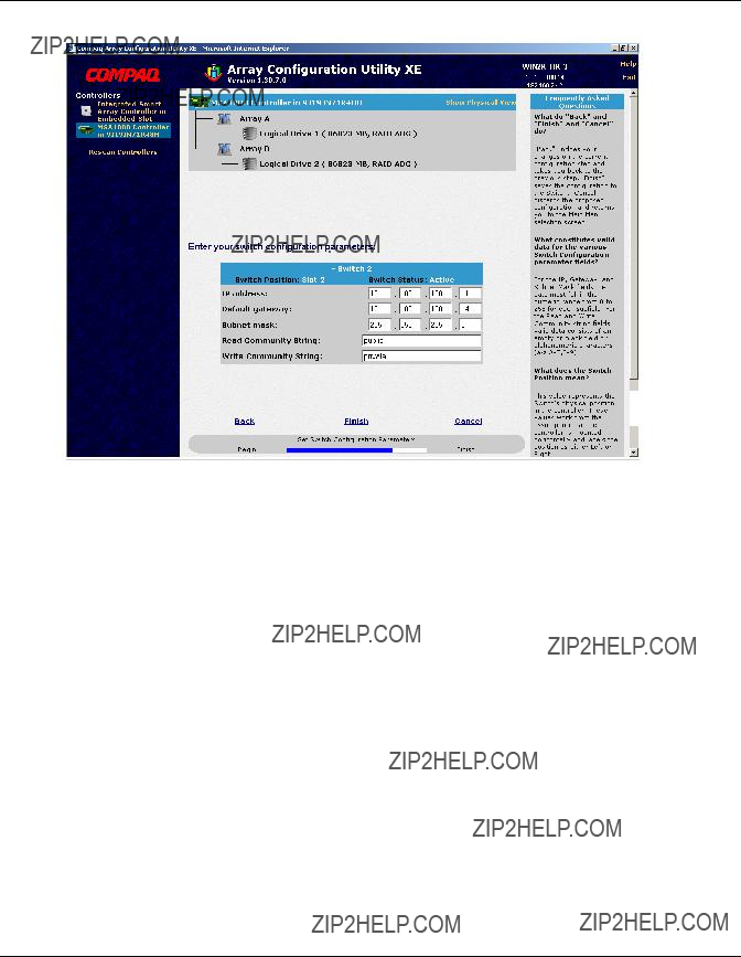
Initial Configuration of the Switch
Figure
2.Enter the following information:
???IP Address
???Default Gateway
???Subnet Mask
???Read and Write Community strings
3.Click Finish to save the settings.
4.Repeat these procedures to set up another switch, if necessary.
Initial Configuration of the Switch
Advanced Switch Configuration
After the initial configuration of the switch is completed, additional switch configuration tasks become available.
As illustrated in Figure
Parameters more advanced than those offered by
Figure
NOTE: Before using the

3
MSA Fabric Switch 6 Management Utility
This chapter describes how to use the Management Utility on the MSA Fabric Switch 6. The following sections describe the process to launch the Management Utility on your switch:
???Defining System Requirements
???Launching the Management Utility
???Describing the Console
???Using the Management Utility
MSA Fabric Switch 6 Management Utility
Defining System Requirements
The MSA Fabric Switch 6 Management Utility runs as a Java applet in a Netscape or Microsoft web browser and works with the versions shown below:
???Microsoft Internet Explorer version 5.5 or later
???Netscape Navigator version 4.75 or later
???Java Runtime Environment, Standard Edition, version 1.3.1 or later
The Java
To download the Java
1.Go to http://java.sun.com/ using Netscape Navigator or Internet Explorer.
2.Select J2SE technology.
3.Select J2SE downloads.
4.Scroll down the list and select
5.Follow the download instructions.
To install Java
1.Insert the MSA1000 Support Software CD in CD drive of your Server.
2.Select Browse CD Contents.
3.Navigate to and select the Misc folder.
4.Click
MSA Fabric Switch 6 Management Utility
Launching the Management Utility
To access your MSA Fabric Switch 6 using the Management Utility, you must configure it with an IP address using the Array Configuration
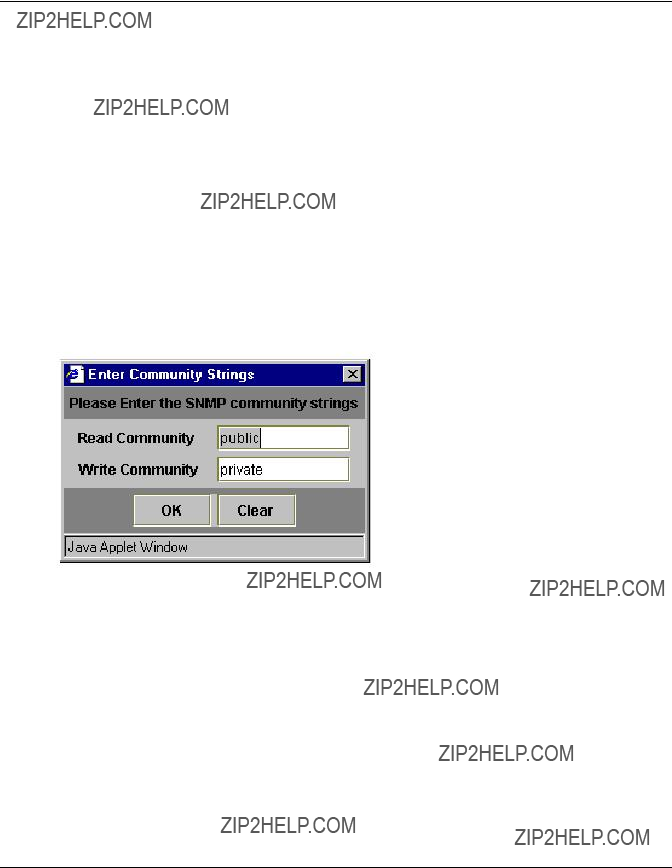
1.Use Compaq Insight Manager (CIM XE) or enter the IP address of the switch you want to manage into the web browser???s address box.
2.Once the Utility is launched, enter the SNMP ???Read Community??? and ???Write Community??? strings into the appropriate test boxes.
NOTE: These strings are
3. Click the OK button.
Figure
NOTE: If the display properties on your computer system are set to ???256 colors,??? the Community Strings window will appear patterned and unclear. Change your display properties setting to either ???True Color (32 bit)??? or ???High Color (16 bit)??? for a sharp, clear image. You will find the display properties setting under Start\Settings\Control Panel\Display\Settings or
MSA Fabric Switch 6 Management Utility
Describing the Console
The Management Utility provides a
???Task Selection Toolbar
???Status Panel
???Main Management Panel
Figure
MSA Fabric Switch 6 Management Utility
Task Selection Toolbar
The Task Selection toolbar is comprised of five buttons and is located in the upper left corner of the screen. Selecting one of these buttons determines which of the management tasks you will operate using the Management Utility.
Figure
Figure
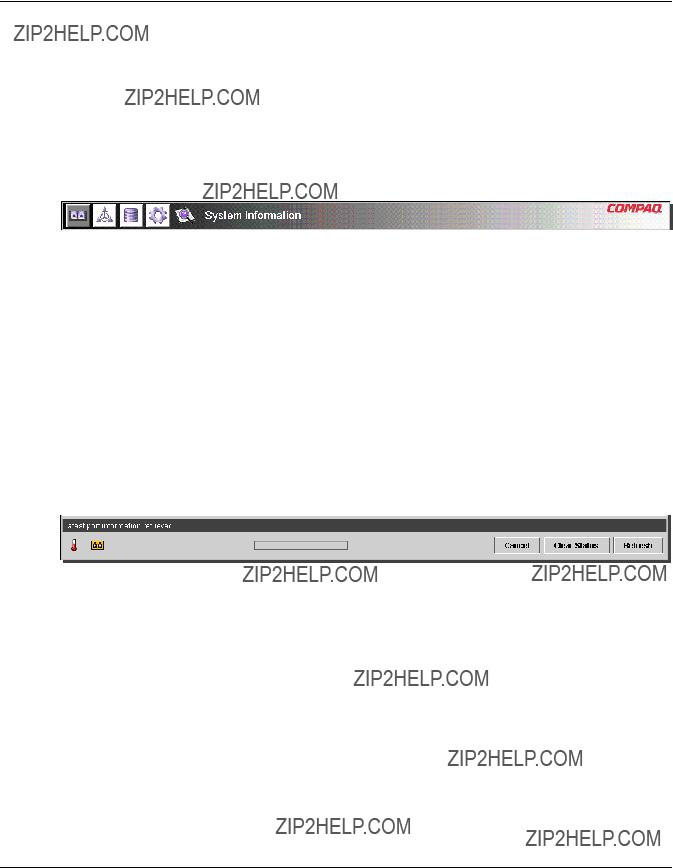
Status Panel
The Status Panel is located at the bottom of the console screen and is shown in Figure
???Switch Status Indicators
???Message Text Line
???Progress Indicator Bar
???Control Buttons, including Cancel, Clear Status, and Refresh.
Figure
MSA Fabric Switch 6 Management Utility
Switch Status Indicators
The switch indicators in the Status Panel display the operating condition of the switch, as described in the following table.
Table
Message Text Line
The Message Text Line displays important information. This information can include what events have occurred, what activities are being performed, and what error messages are issued (in
MSA Fabric Switch 6 Management Utility
The following table lists the error messages shown on the Message Text Line. To view detailed information about an error message, select the System Information button and then the Events Tab or select the Port Information button then the Events Tab.
Table
Progress Indicator Bar
The Progress Indicator bar displays the percentage of progress completed during a transfer of information between the MSA Fabric Switch 6 and StorageWorks Management Utility, such as during a retrieval, refresh, or update action.

MSA Fabric Switch 6 Management Utility
Control Buttons
Three Control buttons are located next to the Progress Indicator bar. Their functions are described in the following table.
Table
Main Management Panel
The Main Management panel is the section of the console that is used for most management operations. The content of this panel is determined by one of the following buttons:
???Port Information
???System Information
???Device View
???Session Configuration
???Help

MSA Fabric Switch 6 Management Utility
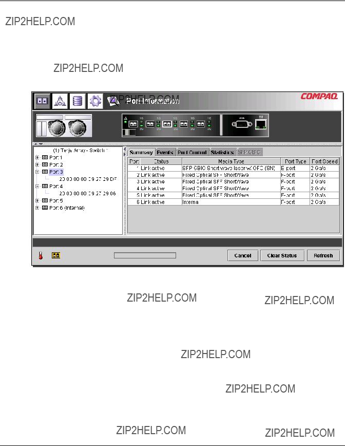
Port Information
When the Port Information button is selected from the Task Selection toolbar, the Port Information window is displayed as shown in the following figure. This display consists of a graphic representation of the switch being monitored at the top of the window, a tree representation of the switch, its ports, and connected devices in the left portion of the window, and a set of five tabbed configuration panels.
???Port Summary Tab
???Port Events Tab
???Port Control tab
???Port Statistics Tab
???SFP Tab
If you select the switch from the menu tree, the Summary and Events tabs will be available while the other tabs will be grayed out and unavailable. If you select a port from either the switch graphic at the top of the window or the menu tree, the Configuration, Statistics, and SFP tabs become available. These contain management information about the port selected. The SFP tab will only be displayed if SFP information is available for the port.
NOTE: No SFP tab will be displayed when an SFP is not installed in the switch or when an installed SFP does not make any information available.
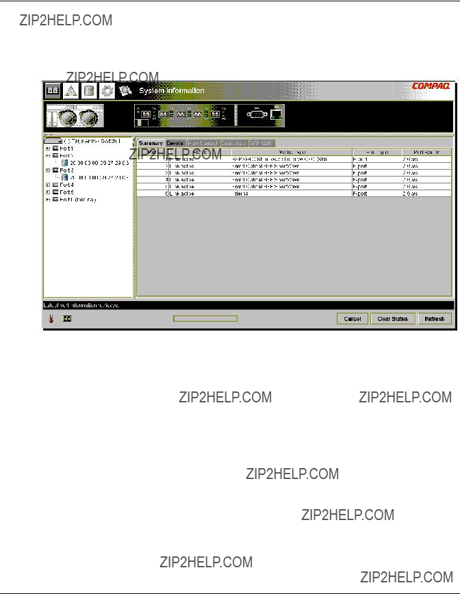
MSA Fabric Switch 6 Management Utility
In addition, the indicators that are displayed on the switch graphic reflect the indicators that are configured on the switch and display the same status that is currently on the switch being monitored.
Figure
MSA Fabric Switch 6 Management Utility
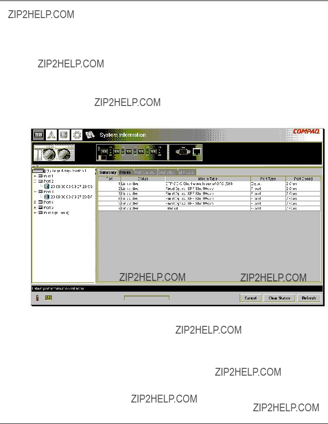
System Information
When the System Information button is selected from the Task Selection toolbar, you can manage and monitor global parameters for the switch. It provides a set of tabbed panels that provide access to a set of 8 switch management functions and is displayed in the following figure.
Figure
MSA Fabric Switch 6 Management Utility
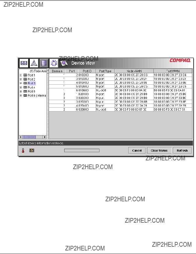
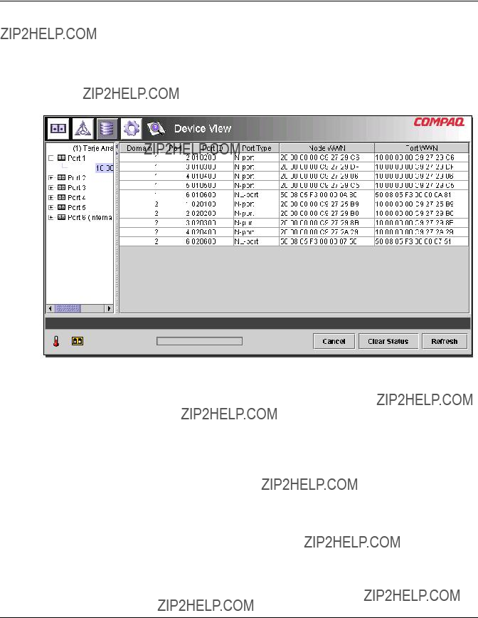
Device View
When the Device View button is selected, a table displays information for connected devices, as shown in the following figure. The devices displayed in the table can be filtered by selecting the switch, a port, or a device from the tree. Selecting the switch will show all the devices, selecting a port will show only the devices connected to that port, and selecting a device will show only that device.
Figure
MSA Fabric Switch 6 Management Utility
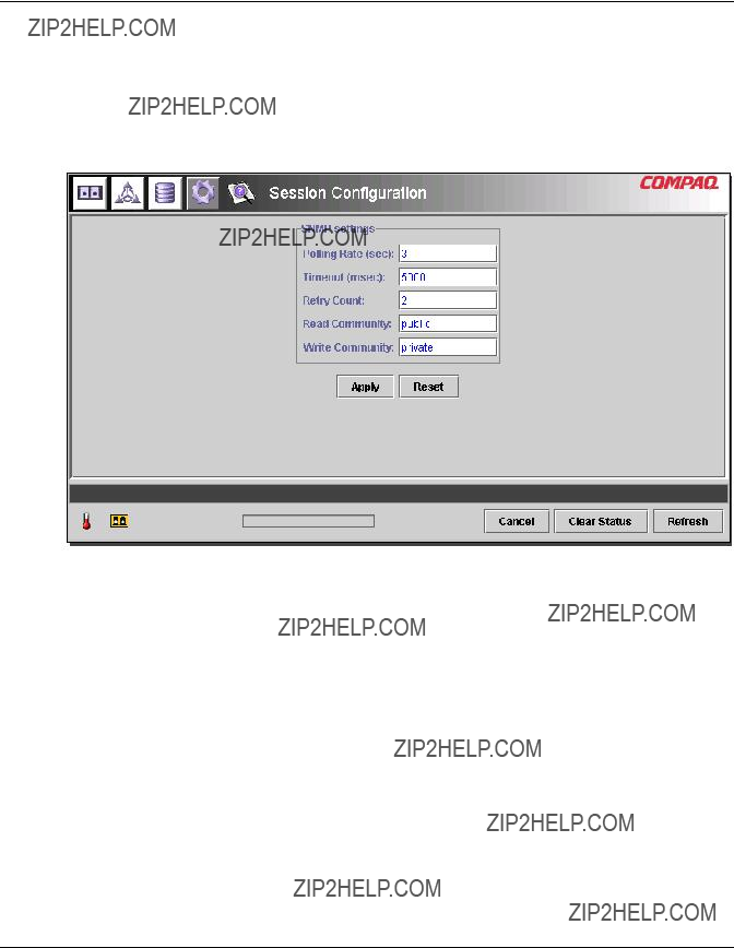
Session Configuration
When the Session Configuration button is selected, the SNMP settings are provided for this session of the Management Utility application, as shown in the following figure. They can be viewed or modified from this window.
Figure
MSA Fabric Switch 6 Management Utility
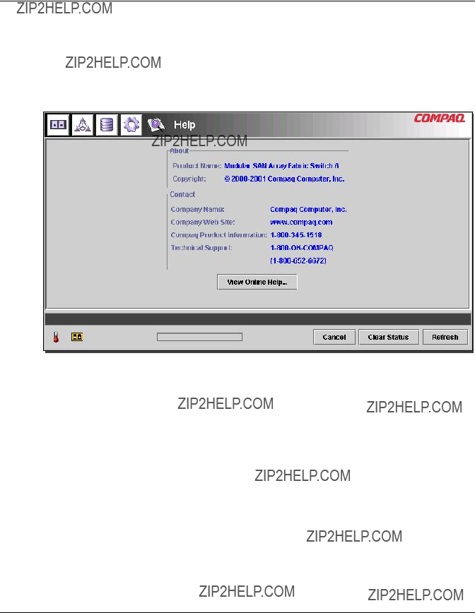
Help
When the Help button is selected, the application information and service contact information is provided as well as access to the
Figure

MSA Fabric Switch 6 Management Utility
Using MSA Fabric Switch 6 Management Utility
The Management Utility lets you manage and monitor a Fabric Switch 6 remotely through a
???Managing and Monitoring individual ports
???Managing from the system information panel
???Monitoring from the Device View
???Session Configuration
???Setting up Zoning
Each of these topics is discussed in the following sections.
Managing and Monitoring Individual Ports
The Port Information task is accessed by clicking the Port button in the Task Selection toolbar as shown in Figure
MSA Fabric Switch 6 Management Utility
Figure
This view provides information about configuration and operation of all of the ports on the MSA Fabric Switch 6 being monitored. It also provides configuration and operation information about individual ports that are selected from either the tree representation or the switch graphic. It consists of the following five tabbed pages:
???Port Summary Tab
???Port Events Tab
???Port Control Tab
???Port Statistics Tab
???Port SFP Tab
Each of these tabs and their management functions is described in the following sections.
MSA Fabric Switch 6 Management Utility
Port Summary Tab
The Port Summary window is the default foreground display when the Port button on the toolbar is clicked. It consists of a table that describes the status and configuration of each of the ports on the switch. The following figure is an example of this display.
Figure
The Port Summary window displays current information about the port as described in the following table.
MSA Fabric Switch 6 Management Utility
Table
MSA Fabric Switch 6 Management Utility
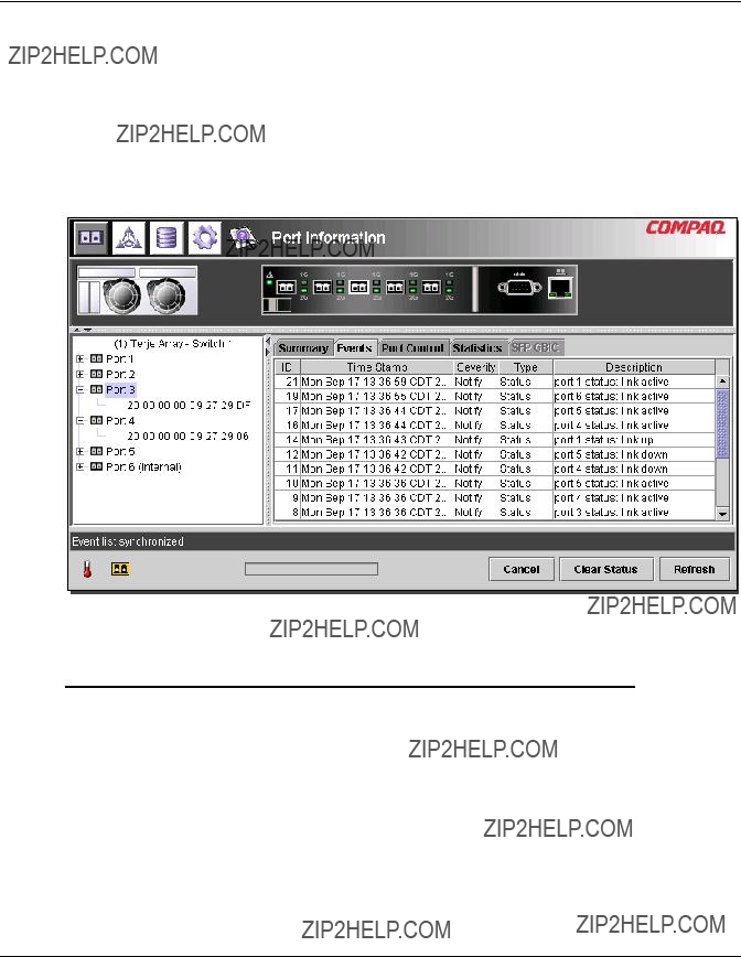
Port Events Tab
The Port Events window is accessed by clicking the ???Events??? tab of the Port Information display. It consists of a table that lists all of the ports related events generated by the MSA Fabric Switch 6 being monitored as shown in the following figure. This events table, as shown in the following figure, displays the parameters described in the following table for each event logged.
Figure
Table
MSA Fabric Switch 6 Management Utility
Table
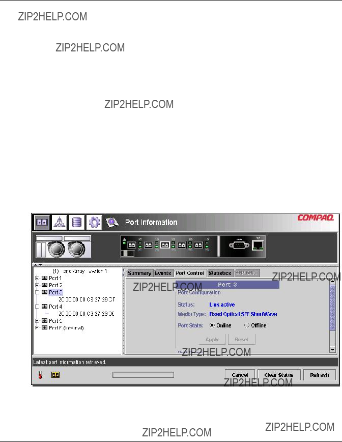
Port Control Tab
The Port Control window is accessed by clicking the ???Port Control??? tab of the Port Information display. The Port Control window consists of two boxes, Port Configuration and Port Reset that provide port status information and port configuration for the port selected. The figure that follows is an example of the Port Control display.
Figure
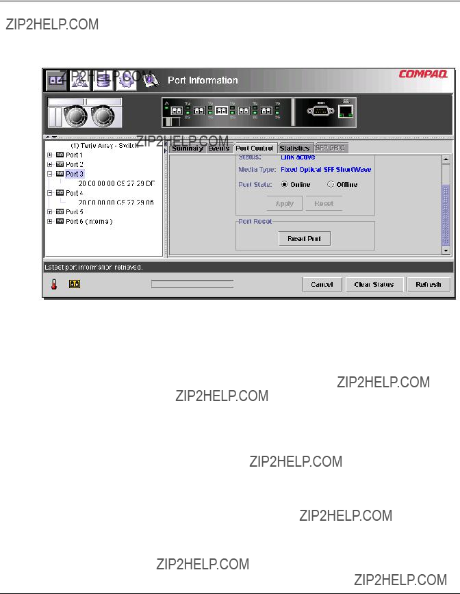
MSA Fabric Switch 6 Management Utility
The following figure provides an example of the Port Reset display (you must use the
Figure
MSA Fabric Switch 6 Management Utility
The Port Control panel displays current information about the port as described in the following table.
Table

MSA Fabric Switch 6 Management Utility
Table
MSA Fabric Switch 6 Management Utility
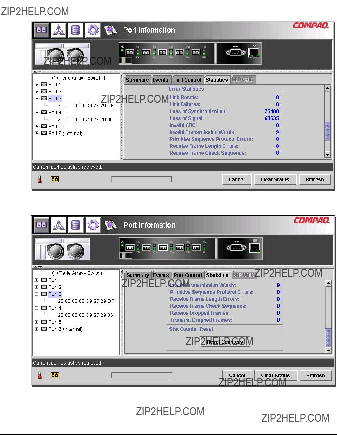
Port Statistics Tab
The Port Statistics window is accessed by clicking the ???Statistics??? tab in the Port Information display. It consists of the following three separate panels with statistics for the port selected:
Transmitted/Received Statistics contains the port number monitored and the number of occurrences of the parameters shown in the following table.
Table

Error Statistics contains the number of occurrences of the statistics and error parameters shown the following table. Except for Link Resets, all of the parameters listed here are a part of the link error status block. You must use the scroll down to bring this into view.
Table
MSA Fabric Switch 6 Management Utility
Table
Stat Counter Reset ??? Contains a button that gives you the ability to reset the statistical counters. Selecting this button will reset all the counters in the switch to zero. You must use the scroll down to bring this into view. The following figures provide an example of the Port Statistics tab, the Error Statistics View, and the Stat Counter Reset view.
Figure
MSA Fabric Switch 6 Management Utility
Figure
Figure
MSA Fabric Switch 6 Management Utility
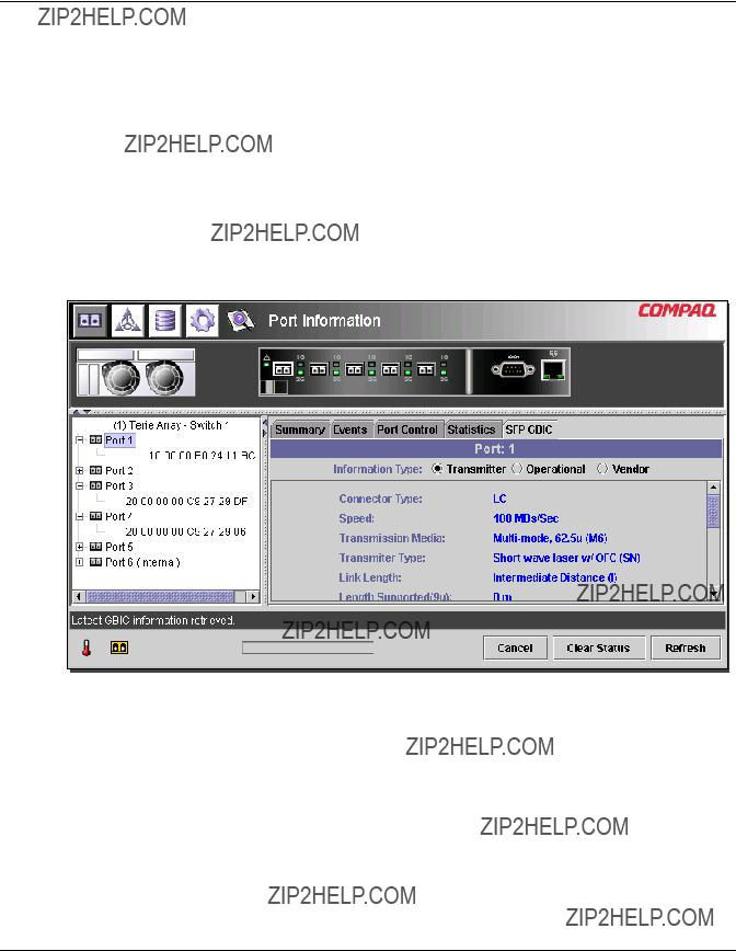
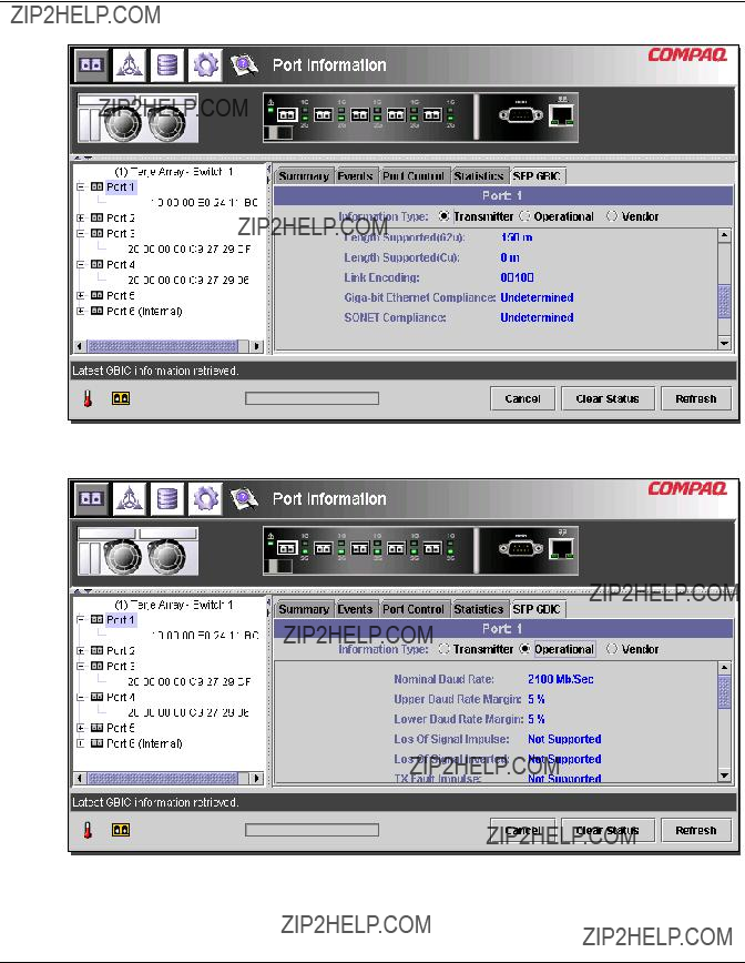
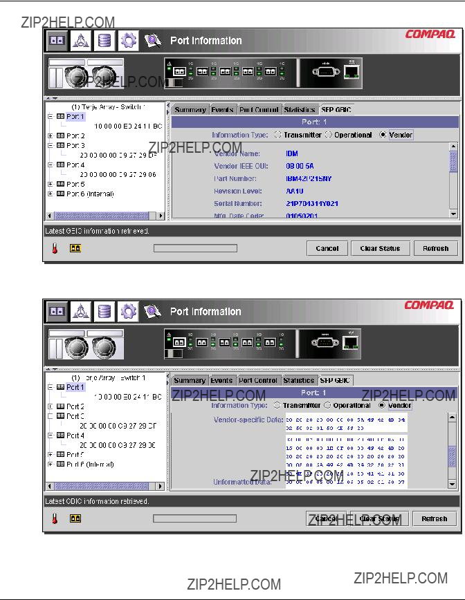
Port SFP Tab
The Port SFP window is accessed by clicking the ???SFP ??? tab in the Port Information display. It allows you to view information about the SFP on the selected port from any of the following categories: Transmitter, Operational, Vendor, Shortwave, and Longwave.
Use the
Figure
MSA Fabric Switch 6 Management Utility
Figure
Figure
MSA Fabric Switch 6 Management Utility
Figure
Figure
MSA Fabric Switch 6 Management Utility
Managing from the System Information Panel
Selecting the System Information button brings up the System Information panels of the Fabric Switch 6 Management Utility display. This display allows you to perform a variety of management and monitoring functions relevant to the MSA Fabric Switch 6 you are managing, as shown in the following figure.
Figure
The System Information is used to manage
???Health Tab
???Information tab
???Switch Control Tab
???Network Tab
???Service Tab
???Firmware Tab

MSA Fabric Switch 6 Management Utility
???Backup/Restore Tab
???Events Tab
Each of these tabs and their management functions is described in the following sections.
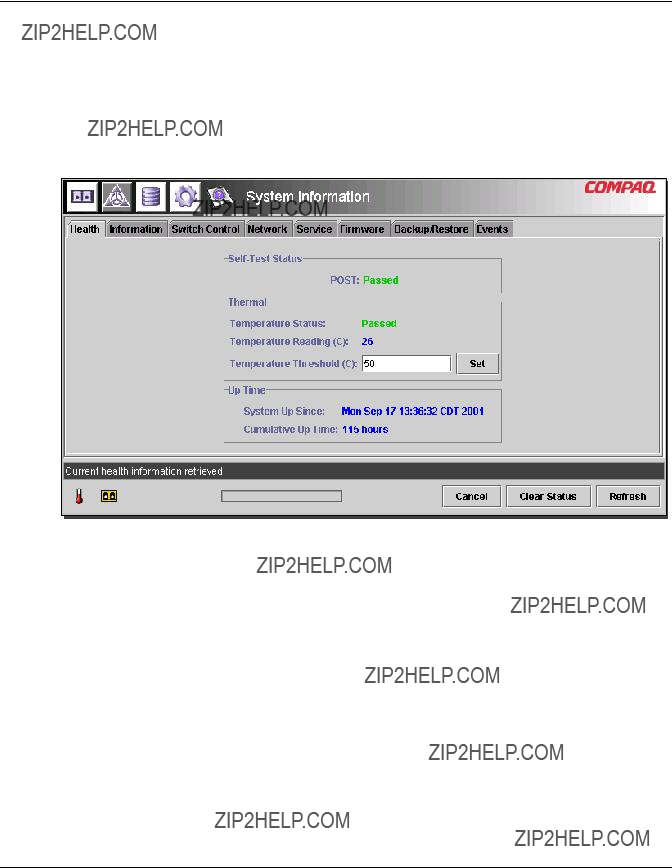
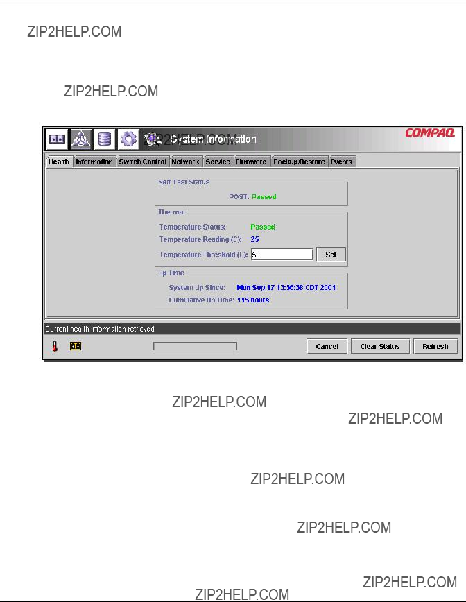
Switch Health Tab
The Switch Health window is the default tab that is displayed when the System Information button is clicked for the first time. It can also be displayed by clicking the ???Health??? tab. It consists of the following three separate boxes that provide operating information about the switch being managed:
???
???Thermal
???Up Time
The following figure provides an example of this display.
Figure
MSA Fabric Switch 6 Management Utility
The following table lists each of the parameters in this display.
Table
MSA Fabric Switch 6 Management Utility
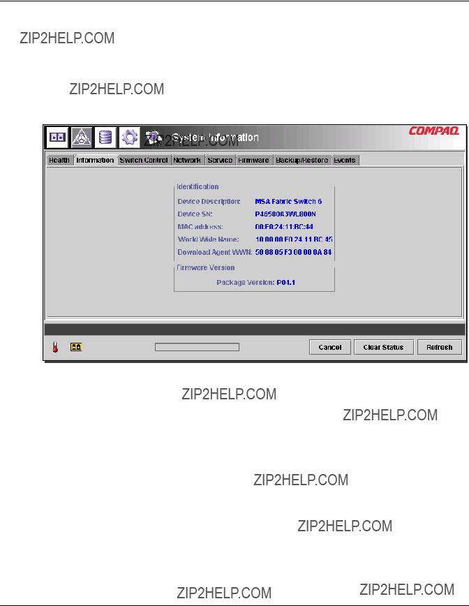
Information Tab
The Information window is accessed by clicking the ???Information??? tab of the System Information display. It consists of two separate panels that provide identification and firmware version information about the switch being managed. The following figure is an example of this display.
Figure
MSA Fabric Switch 6 Management Utility
The following table lists each of the parameters in this display.
Table
MSA Fabric Switch 6 Management Utility
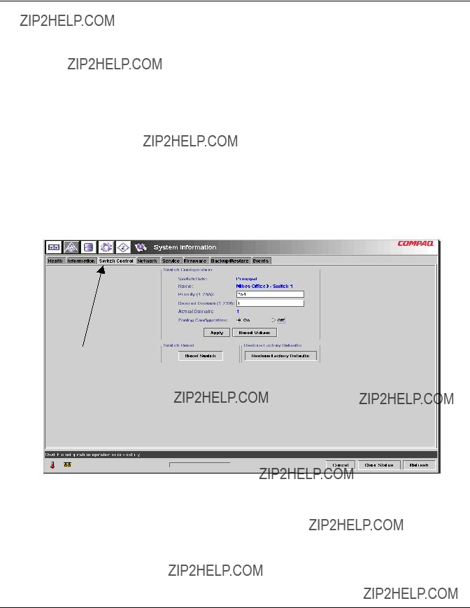
Switch Control Tab
The Switch Control window is accessed by clicking the ???Switch Control??? tab of the System Information display. It consists of three panels: ???Switch Configuration,??? ???Switch Reset,??? and ???Restore Factory Defaults??? as shown in the following figure.
Figure
MSA Fabric Switch 6 Management Utility
The following table lists each of the parameters in this display. The parameters in this configuration are set by typing the new value into a text box or selecting a radio button and clicking the Apply button in the Switch Configuration box. The Reset Values button in the Switch Configuration box returns the parameters to their previous settings.
Table
MSA Fabric Switch 6 Management Utility
Table
MSA Fabric Switch 6 Management Utility
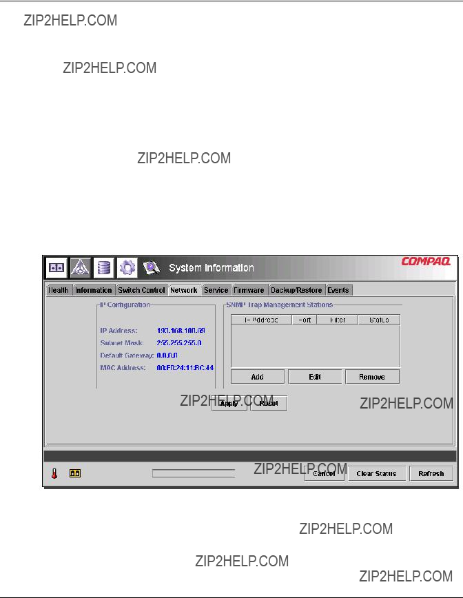
Network Tab
The Network window is accessed by clicking the ???Network??? tab of the System Information display. It consists of the following two panels:
???IP Configuration
???SNMP Trap Management Stations
NOTE: The System Information - Network Tab page will not function properly without a valid gateway address. If you are using the default gateway address (0.0.0.0) or an invalid gateway address, you will need to change the address to a valid one. To check the gateway address on your system using the CLI, see the section titled ???NetCfg???. To change the gateway address using the CLI, see the section titled ???Setting the Gateway Address.???
IP Configuration This panel, as shown in the following figure, displays all of the IP networking parameters that were set on the Fabric Switch 6 using the serial interface.
Figure
MSA Fabric Switch 6 Management Utility
The following table lists the parameters of this panel.
Table
SNMP Trap Management Stations??? This panel, as shown above in Figure
???To add a station, type its IP address and Port Number in the top text boxes in this panel and click the Add button.
???To remove a station from receiving traps from this Fabric Switch 6, highlight its IP address in the list box at the bottom of this panel and click the Remove button.
???To apply the changes, click the Apply button. To undo all the changes and reset the display to the original settings, click the Reset button.
NOTE: The port number entered should be a valid port address. Most systems support a range of
MSA Fabric Switch 6 Management Utility
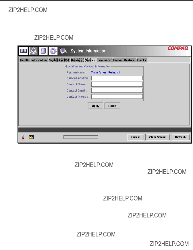
Service Tab
The Service window is accessed by clicking the ???Service??? tab of the System Information display. It consists of the ???Location and Contact Information??? panel as shown in the following figure.
Figure
This window allows you to read the location and contact information that is currently configured for the switch and to modify it by selecting it and editing.
All the information in this panel is for informational purposes only. The switch does not use any of this information to perform functions. For example, the switch will not send out emails to the email address listed. However, some management applications, including future versions, may display some of the information listed on the Service tab page.
MSA Fabric Switch 6 Management Utility
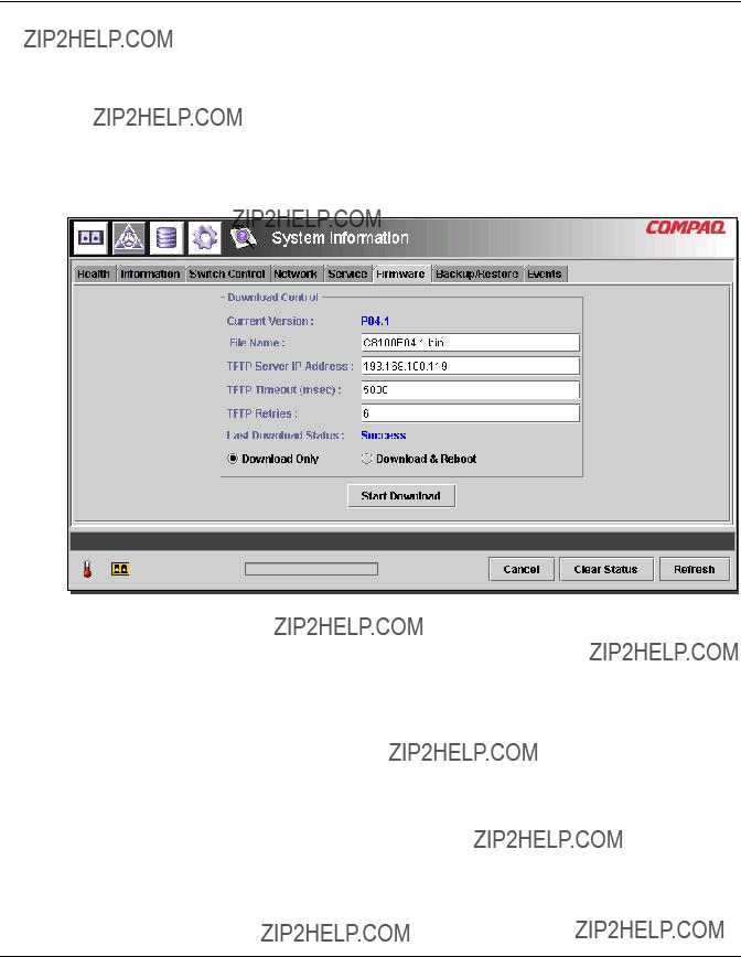
Firmware Tab
The Firmware window is accessed by clicking the ???Firmware??? tab of the System Information display. This window, as shown in the figure below, allows you to download new firmware to your MSA Fabric Switch 6. To perform a download using this interface, fill in the text boxes, click the appropriate radio button, and click the
Start Download button.
Figure
MSA Fabric Switch 6 Management Utility
The following table lists the parameters in the ???Download Control??? panel.
Table
MSA Fabric Switch 6 Management Utility
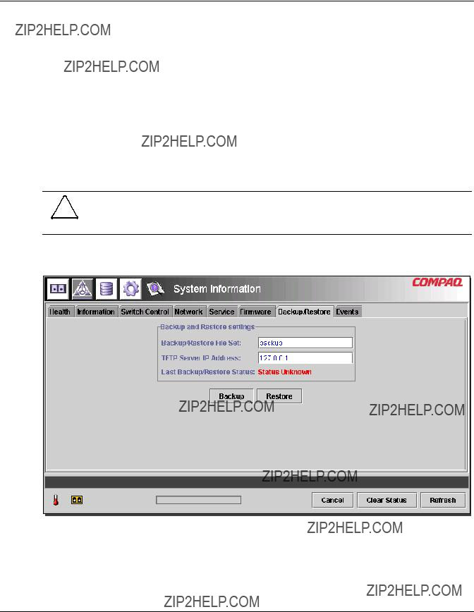
Backup/Restore Tab
The Backup/Restore window is accessed by clicking the ???Backup/Restore??? tab of the System Information display. It consists of one panel titled: ???Backup and Restore Settings.??? Using this interface, you can save the current configuration parameters of the switch to a named TFTP server. You can also restore any previously saved configuration to the switch.
To perform either a backup or restore operation, enter the correct parameters for ???Backup/Restore File Set??? and ???TFTP Server IP Address??? and click either the
Backup or Restore button.
CAUTION: TFTP servers will create new files with modified filenames, resulting in ???restore??? not retrieving the expected file. Be sure to verify that the TFTP server you are using overwrites existing files to avoid this issue.
The following figure is an example of the Backup/Restore tab.
Figure
MSA Fabric Switch 6 Management Utility
The following table lists each of the parameters in this display.
Table
MSA Fabric Switch 6 Management Utility
Events Tab
The Events window is accessed by clicking the ???Events??? tab of the System Information display. It consists of a table that lists all of the events generated by the switch being monitored as shown in the following figure. Also included on this page are two
Figure
MSA Fabric Switch 6 Management Utility
This Event log, as shown in the above figure, displays the parameters described in the table below for each event logged.
Table
MSA Fabric Switch 6 Management Utility
Monitoring from the Device View
Selecting the Device View button brings up Device View display. This display allows you to monitor devices connected to the switch, as shown in the following figure.
Figure
Depending on the icon selected in the tree, the Device View provides the following information about the switch, the ports, or the devices connected to the switch. Selecting members from the tree acts like a list filter. Selecting the switch in the tree will list information about all the devices connected to the switch. Selecting a port in the tree will list information about the selected port only. Selecting a device in the tree will list information about the selected device only.
???Port ??? The port number on the switch.
???Node Type ??? The type of device connected to the port. For example, Storage Device, or Raid Array. In cases where it is not possible to determine the device type, it will be listed as ???unknown.???
???Remote Port Type ??? The type of port on the attached device.
MSA Fabric Switch 6 Management Utility
???WWN ??? The World Wide Name of the device connected to the port.
???WWPN ??? The World Wide Port Name of the device connected to the port.
Session Configuration
Selecting the Session Configuration button allows you to view the current SNMP settings used by the Fabric Switch 6 and change them by typing new values in the text boxes.
???To change a value, type the new values in the text boxes and click Apply.
???To return the settings to their previous values, click Reset.
NOTE: If the community strings specified do not match what is configured in the switch, the application will not be able to communicate with the switch.
The parameters for Session Configuration are described in the following table.
Table

MSA Fabric Switch 6 Management Utility
Table
NOTE: If the display properties on your computer system are set to ???256 colors,??? the Community Strings window will appear patterned and unclear. Change your display properties setting to either ???True Color (32 bit)??? or ???High Color (16 bit)??? for a sharp, clear image. You will find the display properties setting under Start\Settings\Control Panel\Display\Settings or right- click your desktop and select Active Desktop\Customize\Settings.
Setting up Zoning
Zoning is a function of the MSA Fabric Switch 6 that allows you to create isolated Fibre Channel networks with a limited number of connected devices. By limiting the number of devices in a zone, you can obtain more robust performance and enhance access protection.
Zoning is compliant with the following standards:
???
???
???
MSA Fabric Switch 6 Management Utility
This section describes the zoning functions supported by the MSA Fabric Switch 6. It describes zoning at the individual switch and describes how the merge command functions are used to support zoning across a Fabric.
Zoning Elements
Before setting up zoning, you must understand the following zoning elements:
???Zone Members
???Zones
???Zone Sets
CAUTION: Never add a zoned switch to an established fabric that has no zoning. If a switch configured with zoning is added to a fabric that has no configured zoning, the fabric???s HBAs and targets will no longer be able to communicate and the traffic in the fabric will be disrupted. For best results, only add a switch configured with zoning to a fabric configured with the same zoning configuration.
Zone Members
Zone members are Fibre Channel edge devices that are identified by their World Wide Port Name (WWPN). Any device that you want to include in a zone must be identified as a zone member. While internally the zone members are tracked by their WWPN, you can create a Zone Member Name that acts as an alias for the device. This makes it easier to identify the devices during configuration and operation. The following are examples of Fibre Channel devices that can be named as zone members:
???Servers
???Raid systems
???Disk drives
???Tape libraries
IMPORTANT: The World Wide Node Name (WWNN) of the Fibre Channel device cannot be used to create a zone member.

MSA Fabric Switch 6 Management Utility
Zones
Zones are logical entities that represent groupings of zone members. Each zone must be assigned a unique zone name when it is defined.
Zone Sets
Zone sets are logical entities that represent groupings of zones. They define a zoning configuration. Each zone set is assigned a unique zone set name when it is defined. The MSA Fabric Switch 6 allows storing of multiple zone sets. However, only one of these zone sets can be active at a time. The other zone sets can be used as backup, trials, or other
Naming Rules for Zone Members, Zones, and Zone Sets
Zone member, zone, and zone set names must follow these rules:
???Names must be between 1 and 64 characters long
???Characters used in names must be 7 bit ASCII characters
???The first character of a name must be a letter
???Other characters of the name (any characters besides the first character) can be a letter
???No spaces are allowed in the name
MSA Fabric Switch 6 Management Utility
Zoning Limitations for Zone Members, Zones, and Zone Sets
There are zoning limitations for individual switches and fabrics. See Table
Table
Two Ways to Display Zoning
The MSA Fabric Switch 6 Management Utility allows you to display zoning in two ways:
???Merged zones
???Local zones
To toggle between the Merged Zones display and the Local Zones display, expand the Zoning View
Merged Zones
Use the Merged Zones display when you are interested in viewing information for zones merged with other switches on the Fabric.
This view is
NOTE: Because only one Zone Set can be active across the entire Fabric, only the Active Zone Set is shown.

MSA Fabric Switch 6 Management Utility
Local Zones
Use the Local Zones display when you are interested in viewing, creating, or editing zone sets, zones, and zone members for the switch presently being monitored.
This view is a read/write
Using the Fabric Switch 6 Management Utility to Configure Zoning
This section describes how to use the MSA Fabric Switch 6 Management Utility to configure Zone Members, Zones, and Zone Sets and how to apply the new or edited zone configurations to the switch.
Setting up Zoning includes:
???Enabling Zoning
???Creating Zone Sets
???Creating Zones
???Creating Zone Members
???Assigning Zone Members to Zones
???Assigning Zones to Zone Sets
???Activating the Zone Set
Each of these procedures is discussed in the following paragraphs.
MSA Fabric Switch 6 Management Utility
Enabling Zoning
IMPORTANT: The Zoning icon and its options are not displayed or accessible until Zoning is enabled.
To enable zoning:
1.In the Switch Control tab of the System Information screen, select the Zoning Configuration On radio button.
Figure
2.Click Apply to accept the change.
The Zoning icon is now displayed next to the other icons at the top of the screen.
Figure
Control tab
MSA Fabric Switch 6 Management Utility
Creating Zone Sets
To create a Zone Set:
1.Select the Zoning icon.
The Zoning Configuration screen is displayed. Figure
IMPORTANT: To create or edit Zone Sets, Zones, and Zone Members, the Local Zones view must be displayed. To change the view in the Zoning Configuration screen, expand the Zoning View
Figure
MSA Fabric Switch 6 Management Utility
2.To create a new Zone Set:
a.In the Zone Sets column of the Zoning Configuration screen, click Add.
b.Enter the name for the Zone Set.
c.Click OK.
3.To create a new Zone Set by modifying an existing Zone Set:
a.In the Zone Sets column of the Zoning Configuration screen, select the existing Zone Set and click Edit.
b.In the Edit window, change the name of the Zone Set to the new name.
c.Click OK.
Creating Zones
To create new Zones:
1.In the Zones column of the Zoning Configuration screen, click Add.
2.Enter the name for the Zone.
3.Click OK.
Creating Zone Members
To enter the devices:
1.In the Zone Members column of the Zoning Configuration screen, click Add.
2.Enter the name of the zone member
3.Select the WWPN from the port number list.
4.Enter the WWPN name, or if the device is already connected to the switch, select the name from the dropdown menu.
5.Click OK.
6.Repeat these steps for each additional Zone Member.

MSA Fabric Switch 6 Management Utility
Assigning Zone Members to Zones
To add the Zone Members to the desired Zones, select the desired Zone Member and use the
Assigning Zones to Zone Sets
To add the Zones to the desired Zone Set, select the desired Zone and use the
Activating the Zone Set
To activate and apply the Zone Set:
1.
2.Click Apply.
The selected Zone Set is now the active Zone Set used by the switch.
Example Zoning Configuration
Assume the following:
???Server1 needs to access Disk1 exclusively for Operating System boot (OS Boot).
???Server1 needs to access Raid1 for shared storage.
???Server1 needs to access Tape1 for backup.
???Server2 needs to access Disk2 exclusively for Operating System boot.
???Server2 needs to access Raid1 for shared storage.
???Server2 needs to access Tape1 for backup.
Before you begin to configure your zoning, you must first define the zone members, zones, and zone sets that you will need.
Table 3 lists the zone members, zones, and zone sets being used in this example and indicates what members the zones and the zone sets contain.

MSA Fabric Switch 6 Management Utility
Table
In this example, the Zone Set
???Web_Zone contains the following Zone Members: Server1, Disk1, Raid1, and Tape1.
???Mail_Zone contains the following Zone Members: Server2, Disk2, Raid1, and Tape1
4
Troubleshooting
This chapter covers the following information about your new MSA Fabric Switch 6.
???Troubleshooting guidelines
???Troubleshooting the MSA Fabric Switch 6 with the status indicator and Reset Button
???Preventive Maintenance Solutions
Troubleshooting Guidelines
If there is a problem accessing a device connected to the switch, the source of the problem can be the MSA Fabric Switch 6 or any of the connections between the host and device. Use this chapter to troubleshoot the MSA Fabric Switch 6.

Troubleshooting
Troubleshooting the MSA Fabric Switch 6
If there is a problem accessing a device connected to the MSA Fabric Switch 6, the source of the problem can be with the device, the switch, the host, or any of the connections between the host and device. Follow the steps outlined below to investigate the problem. The following is a description of possible symptoms:
1.Check the Global Status Indicator for power. The unit may not be plugged into the Modular SAN Array 1000 correctly.
2.Inspect the switch fault indicators for apparent problems. If the fault indicators are on, the switch may be faulty or the temperature may be out of defined limits.
3.Inspect the cabling between the switch and attached Fibre Channel devices. Check for loose, dirty, broken, or bent cabling and connectors. If a Compaq- supported Small Form Factor Pluggable transceiver (SFP) is in use, check that it is properly inserted and that the cable is properly seated.
4.Check the port status indicators.
Reading the Global Status Indicator
The indicators provide information about the status of the switch. This should be used as the first stage in troubleshooting. If either the serial or the Ethernet link to the switch is running, use the appropriate Command Line Interface command (See Appendix C, ???Command Line Interface,??? for the appropriate command). The Global Status Indicator indicators can be interpreted by reviewing Table
Troubleshooting
Table
If the light remains on after 15 seconds, the switch failed the
If the test fails, the switch may be faulty.
continued
Troubleshooting
Table
Reading the Ethernet Indicators
Table

The network is down for some reason. Check to see if other systems on the network are functioning.
The switch is not connected to the network. Check the cable to see if it is seated properly. Try replacing the cable.
The switch is not functioning. Is the GSI power showing to the switch? Can you communicate with it via the serial port?
The switch may be connected to a network that is not 10Base T compatible. It could be 100BaseT only, or some other LAN link.
Troubleshooting
Reading the Port Indicators
Table
Serial Communication Problems
The
Connections
The following section describes the proper use of
Troubleshooting
Use caution when handling SFPs. Take normal precautions to protect them from a static electrical discharge and any other damage:
IMPORTANT: Always wear an
???Leave the device in its
???Hold the SFP by its edges and handle it carefully.
???Always follow the
IMPORTANT: Do not install any SFP that appears physically damaged. This may result in permanent damage to the switch. Keep unused SFP connectors covered with the plugs that are shipped with them to prevent contamination from obscuring or attenuating the light signals.
Fibre Channel Cables
The MSA Fabric Switch 6 uses Fibre Channel cables to communicate with
???Inspect the switch fault indicators for apparent problems.
???Check that the
???Check the port status indicators.
???Check to see if the indicator located next to the special Fibre Channel interface cable connector is lit. If it is not, a viable connection to the Fibre Channel network has not been established.
Troubleshooting
Temperature Control
The MSA Fabric Switch 6 is designed to work in a normal room temperature environment, between 10?? and 40?? C (50?? F to 104 ?? F).
Preventive Maintenance Solutions
To protect the switch for longer use, Compaq recommends the following:
???Periodically vacuum the external surfaces of the switch to remove dust.
???Do not drop fiber optic cable connectors onto hard surfaces. This can cause internal glass fractures and intermittent signals.
???Keep unused cable ends covered to prevent contamination from obscuring or attenuating the light signals.
IMPORTANT: Always use an
???Keep unused
???Always follow the
???Never insert foreign objects into optical transmit and receive ports.
???Do not bend fiber cable to less than a
A
Regulatory Compliance Notices
Federal Communications Commission Notice
Part 15 of the Federal Communications Commission (FCC) Rules and Regulations has established Radio Frequency (RF) emission limits to provide an
The rating label on the device shows which class (A or B) the equipment falls into. Class B devices have an FCC logo or FCC ID on the label. Class A devices do not have an FCC ID on the label.

Regulatory Compliance Notices
Federal Communications Commission Notice
This equipment has been tested and found to comply with the limits for a Class A digital device, pursuant to Part 15 of the FCC Rules. These limits are designed to provide reasonable protection against harmful interference when the equipment is operated in a commercial environment. This equipment generates, uses, and can radiate radio frequency energy and, if not installed and used in accordance with the instructions, may cause harmful interference to radio communications. Operation of this equipment in a residential area is likely to cause harmful interference, in which case the user will be required to correct the interference at personal expense.
Modifications
The FCC requires the user to be notified that any changes or modifications made to this device that are not expressly approved by Compaq Computer Corporation may void the user's authority to operate the equipment.
Cables
Connections to this device must be made with shielded cables with metallic RFI/EMI connector hoods in order to maintain compliance with FCC Rules and Regulations.
Canadian Notice (Avis Canadien)
This Class A digital apparatus meets all requirements of the Canadian Interference- Causing Equipment Regulations.
Cet appareil num??rique de la classe A respecte toutes les exigences du R??glement sur le mat??riel brouilleur du Canada.
Regulatory Compliance Notices
European Union Notice
Products with the CE Marking comply with both the EMC Directive (89/336/EEC) and the Low Voltage Directive (73/23/EEC) issued by the Commission of the European Community.
Compliance with these directives implies conformity to the following European Norms (in brackets are the equivalent international standards):
???EN55022 (CISPR 22) - Electromagnetic Interference
???
???EN60950 (IEC950) - Product Safety

B
Electrostatic Discharge
To prevent damage to the system, be aware of the precautions you need to follow when setting up the system or handling parts. A discharge of static electricity from a finger or other conductor may damage system boards or other
To prevent electrostatic damage, observe the following precautions:
???Avoid hand contact by transporting and storing products in
???Keep
???Place parts on a grounded surface before removing them from their containers.
???Avoid touching pins, leads, or circuitry.
???Always make sure you are properly grounded when touching a

Electrostatic Discharge
Grounding Methods
There are several methods for grounding. Use one or more of the following methods when handling or installing
???Use a wrist strap connected by a ground cord to a grounded workstation or
computer chassis. Wrist straps are flexible straps with a minimum of 1 megohm
?? 10 percent resistance in the ground cords. To provide proper ground, wear the strap snug against the skin.
???Use heel straps, toe straps, or boot straps at standing workstations. Wear the straps on both feet when standing on conductive floors or dissipating floor mats.
???Use conductive field service tools.
???Use a portable field service kit with a folding
If you do not have any of the suggested equipment for proper grounding, have an Authorized Compaq Reseller install the part.
NOTE: For more information on static electricity, or for assistance with product installation, contact your Compaq authorized reseller.
C
Command Line Interface
Most of the configuration commands used to set up and maintain the MSA Fabric Switch 6 can be controlled from the main menu???s first two options: Networking Parameters and Management. For more advanced functions, the MSA Fabric Switch 6 Management Utility offers a further level of complexity. This more advanced level of parameters operates from a command line interface (CLI).
This chapter includes information on:
???Invoking the Command Line Interface
???Using the Command Line Interface
???Setting up Zoning
The table below provides an overview of the commands available through the CLI.
Table
Command Line Interface
Table
Command Line Interface
Invoking the Command Line Interface
The CLI can be called up by choosing 4.Command line interface on the main menu. It will respond with a ???cmd>??? prompt, as shown in the following figure.
Figure
Command Line Interface
Using the Command Line Interface
The CLI is a
cmd> help command_name
Figure
By typing the Help command, you can access a list of all available commands along with a brief overview of the syntax. In addition, it is possible to assign values to various parameters by using the equal sign separated by spaces.
Command Line Interface
Logging Out of the CLI
The logout command screen in the CLI is the same as the logout option in the main menu.
Figure
Exiting from CLI
The Exit command of the CLI returns the user to the main menu. The Exit command can be distinguished from the Logout command in that the user does not exit the program but remains logged in and retains the ability to select a new item from the main menu.
Reset
This command resets the switch.
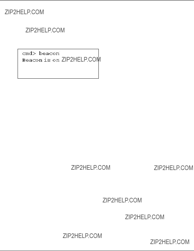
Beacon
The Beacon command enables or disables the switch.
Command Line Interface
Syntax
Beacon On = Set Switch Beacon ON
Beacon Off = Set Switch Beacon OFF
Examples:
Figure
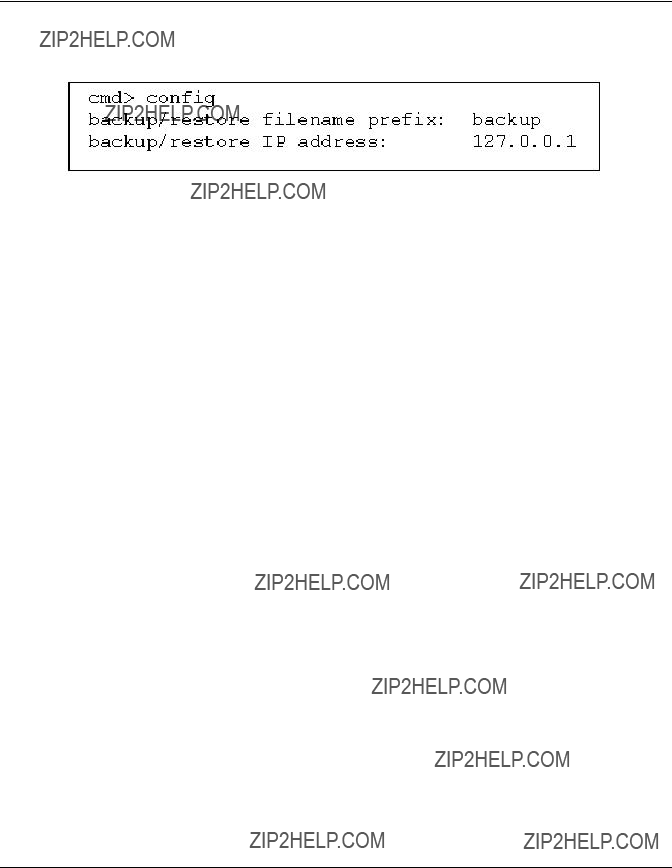
Config
This command displays and modifies the switch configuration backup and configuration restore settings. It also activates the backup and restore function. Configuration backup writes the switch???s configuration files to files specified by ???file??? on the TFTP server specified by the IP address. Configuration restore reconfigures the switch based on the files specified by ???file ??? from the TFTP server specified by the IP address.
NOTE: When using the ???backup??? feature, some TFTP servers may not overwrite existing files. These TFTP servers will create a new file with modified filenames, resulting in ???restore??? not retrieving the expected file.
Syntax:
Command Line Interface
Examples:
Figure
Exit
Exits the command line interface and returns to the main menu.
Syntax
Exit
Examples:
cmd> Exit
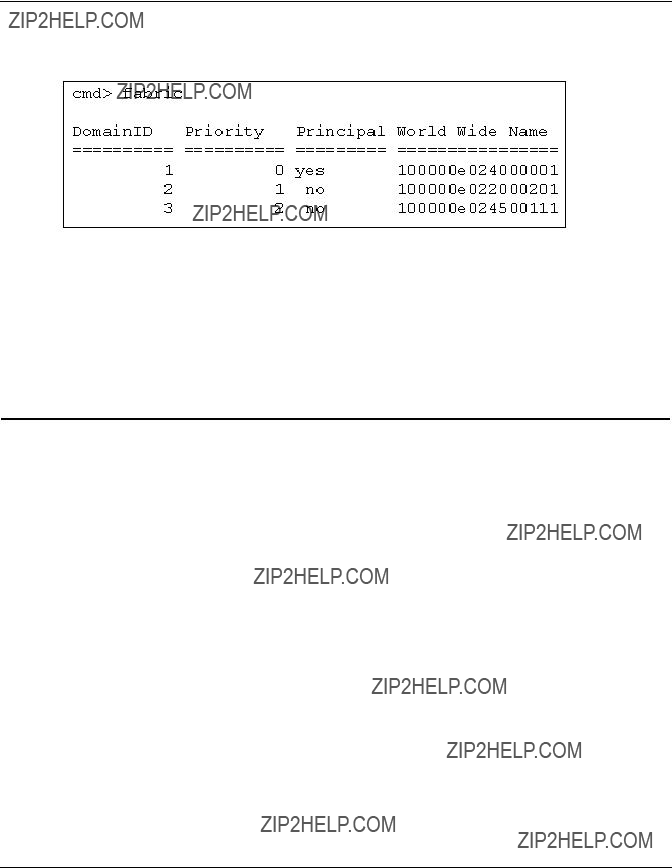
Fabric
Displays all of the switches in the fabric.
Syntax
Fabric
Command Line Interface
Example:
Figure
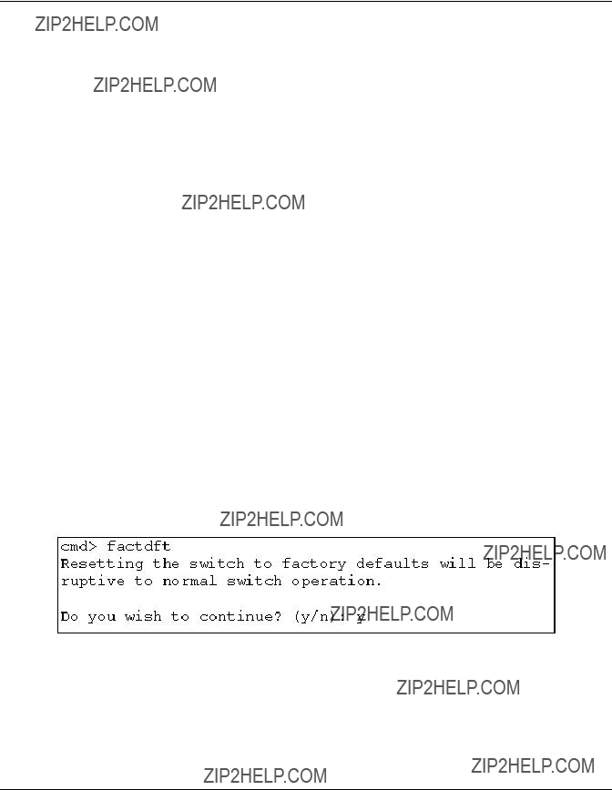
Factdft
Resets the switch in the factory default settings. CLI command factory defaults are:
Table
continued
Command Line Interface
Table
Syntax
FactDft
Example:
Figure
Command Line Interface
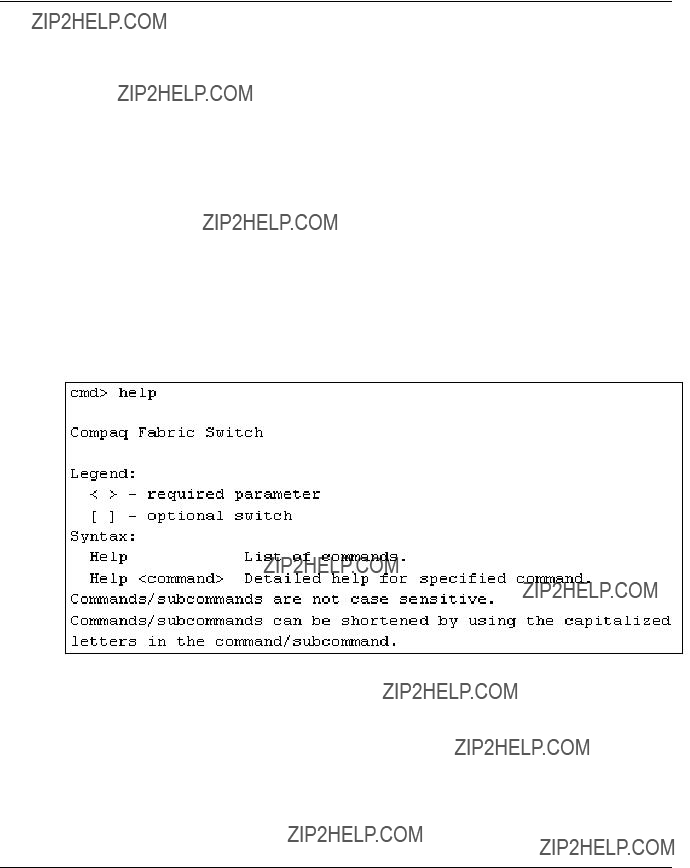
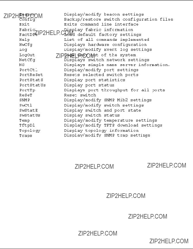
Help
Lists all of the commands. Help is also used with a command name to describe a command function.
Syntax
Help
Help <command>
Help ??? Displays the list of commands that are available from this interface.
Help <command> ??? Displays a description of the command specified. command The name of the command for which you want help.
Examples:
Figure
Command Line Interface
Figure
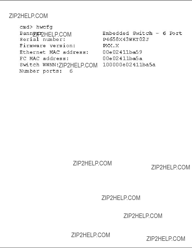
Hwcfg
Displays the hardware configuration of the switch.
Syntax
HwCfg
Command Line Interface
Example:
Figure
Log
This command will display and modify the
Syntax
Command Line Interface
<level>: d ??? debug; i ??? information; w ??? warning; f ??? fatal; s ??? status; g ??? gsos;
<mod>: hex bit field
Example (to set DispLevFilter to debug, warning, fatal):
Log dlf = dwf
Example (to turn LogLevFilter off):
Log llf = n
Example:
Figure
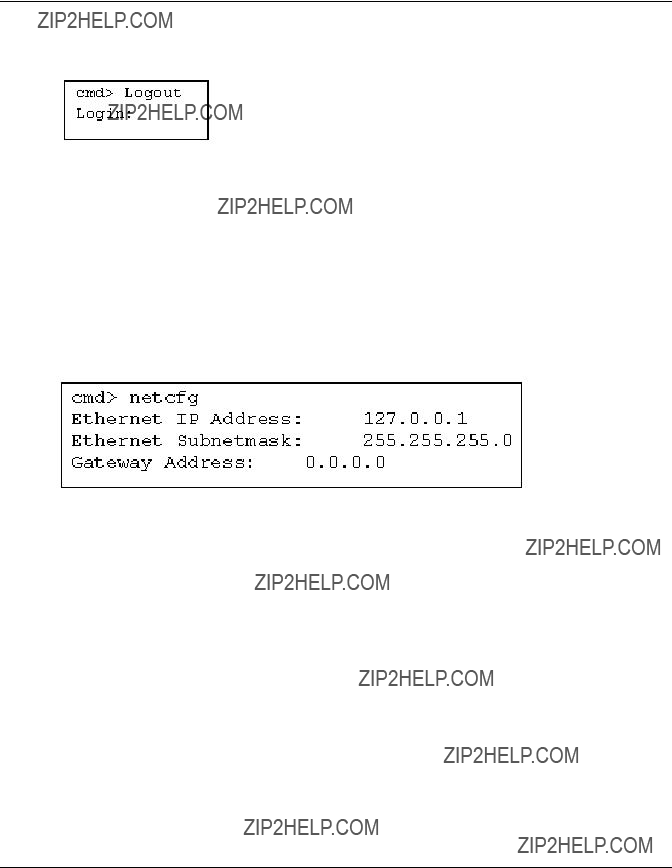
LogOut
Logs the user out of the system.
Syntax
LogOut
Command Line Interface
Example:
Figure
NetCfg
Displays switch network settings.
Syntax:
Netcfg
Examples:
Figure
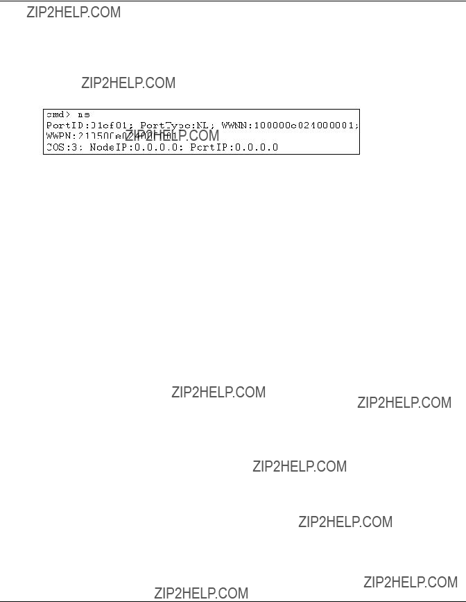
NS
Displays the local and global name server (NS) table entries.
Syntax
NS
NS [/d]
NS All
NS All [/d]
Where setting the /d variable causes all entries to display without pausing to wait for user interaction.
Command Line Interface
NS - Displays local name server entries
NS All - Displays local and global name server entries
Examples:
Figure
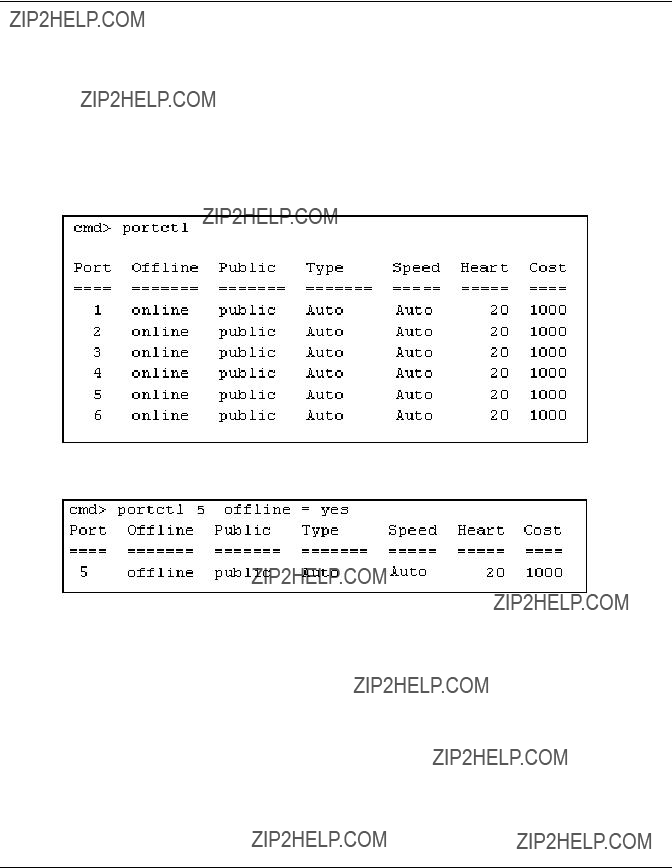
PortCtl
Displays and modifies the port control settings.
Syntax
PortCtl
PortCtl <port_number> Public = <public_state>
PortCtl <port_number> Type = <port_type>
PortCtl <port_number> Speed = <port_speed>
PortCtl <port_number> Heartbeat = <heartbeat_rate>
PortCtl <port_number> Cost = <routing_cost>
where port_number = a valid port number for the Fabric Switch between 1 and 6. Use the value ???all??? if you want the command to apply to all ports.
PortCtl??? Displays the port control settings.
Command Line Interface
PortCtl <port_number> Offline = <offline_state> ??? Sets an individual
port or all ports online or offline.
offline_state variables Description
yes Sets individual port or all ports to offline state. no Sets individual port or all ports to online state.
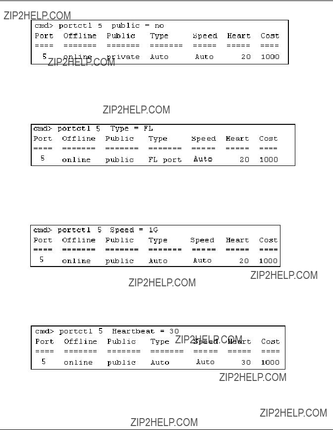
PortCtl <port_number> Type = <port_type> ??? Sets the port type variable for an individual port or all ports.
PortCtl <port_number> Speed = <port_speed> ??? Sets the port type variable for an individual port or all ports.
PortCtl <port_number> Heartbeat = <heartbeat_rate> ??? Sets the heartbeat rate variable for an individual port or all ports.
heartbeat_rate variables Description
5
Command Line Interface
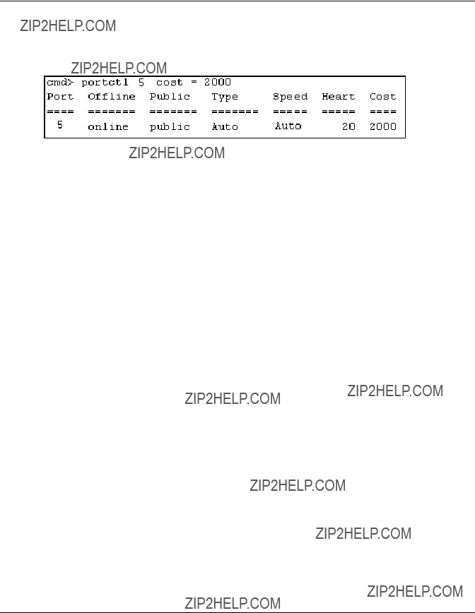
PortCtl <port_number> Cost = <routing_cost> variable for an individual port or all ports.
Figure
Figure
Syntax:
PortCtl <port_number> offline = <offline_state>
Command Line Interface
Figure
Syntax:
PortCtl <port_number> public = <public_state>
Figure
Syntax:
PortCtl <port_number> Type = <port_type>
Figure
Syntax:
PortCtl <port_number> Speed = <port_speed>
Figure
Command Line Interface
Syntax:
PortCtl <port_number> Heartbeat = <heartbeat_rate>
Figure
Syntax:
PortCtl <port_number> Cost = <routing_cost>
PortReSet
This command displays/resets statistic counters for the specified ports.
Syntax:
PortStatS
Displays port statistics and resets port statistics counters.
Syntax
PortStatS
PortStatS <port_number>
PortStatS /r
PortStatS <port_number> /r
where port_number = a valid port number for the Fabric Switch between 1 and 6.
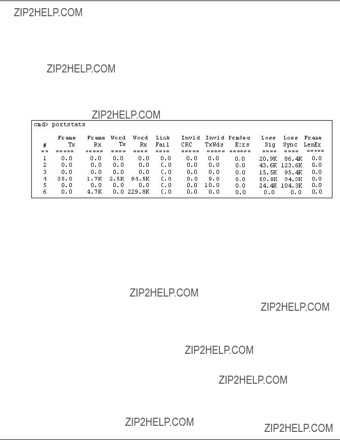
Command Line Interface
PortStatS <port_number> ??? Displays statistics for the port specified on the switch.
PortStatS /r??? Resets the statitics counters for all ports on the switch.
PortStatS <port_number> ??? Resets the statitics counters for the port specified on the switch.
Examples:
Figure
PortStatUs
Displays port status.
Syntax
PortStatUs
PortStatUs <port#>
Portstatus <port_number> <port_number> .. ??? Displays port status for the port specified on the switch.
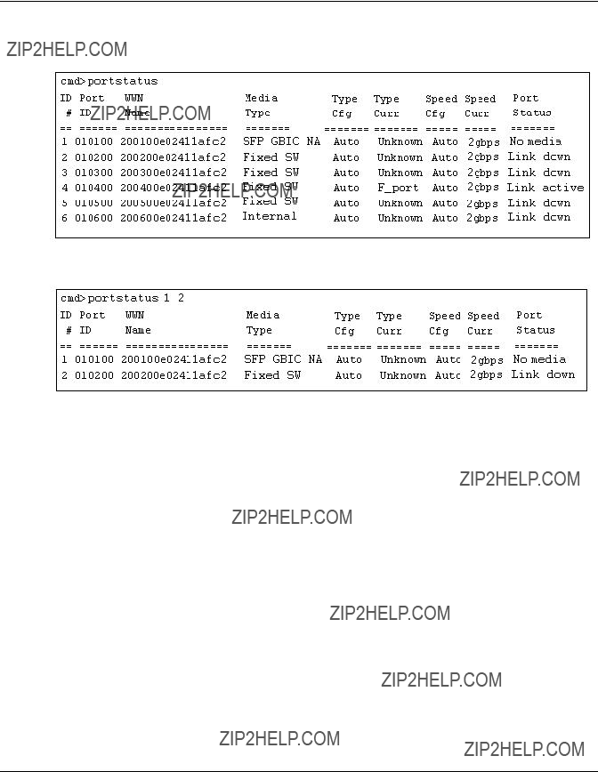
Command Line Interface
Examples:
Figure
Figure
Syntax:
PortStatUs <port_number>
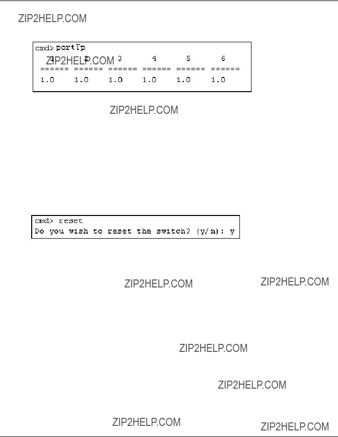
PortTp
Continuously display the throughput for all of the ports. Press any key to stop the display.
Syntax
PortTp
Command Line Interface
Example:
Figure
ReSeT
Resets the Switch
Syntax
Reset
Example:
Figure
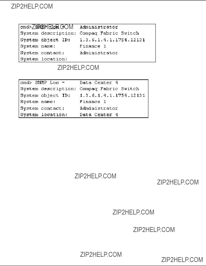
SNMP
Displays and modifies the SNMP system variables.
Syntax
SNMP
SNMP Name = <name_text>
SNMP Con = <contact_text>
SNMP Loc = <location_text>
This command displays or modifies the MIB2 system strings. System contact can contain three pieces of information: name, email address, and phone number. Use ???|??? to separate the name, email address, and phone number fields. For example,
Command Line Interface
SNMP??? Displays the System Description, System Object ID, System Name, System Contact, and System Location for the switch.
SNMP Name = <name_text> ??? Sets the SNMP Name for the switch to the text typed in place of the name_text variable.
SNMP Con = <contact_text> ??? Sets the SNMP Contact for the switch to the text typed in place of the contact_text variable.
SNMP Loc = <location_text> ??? Sets the SNMP Location for the switch to the text typed in place of the location_text variable.
Examples:
Figure
Figure
Command Line Interface
Figure
Figure
Command Line Interface
SwCtl
Displays and modifies the switch control settings.
Syntax
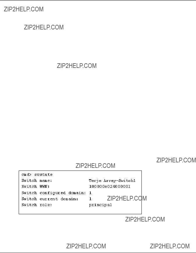
SwStatE
Displays the switch and port state.
Syntax
Swstate
Example:
Figure
Command Line Interface
Figure
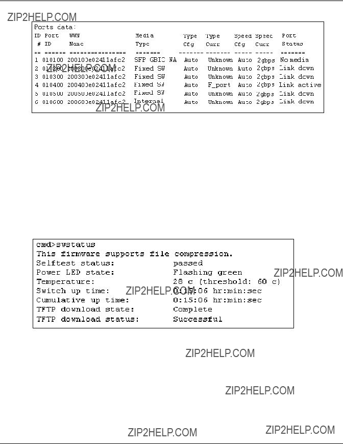
Swstatus
Displays the switch status.
Syntax
Swstatus
Example:
Figure
Command Line Interface
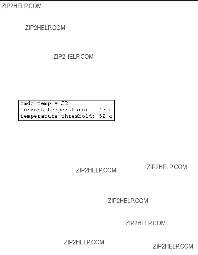
Temp
Displays the current temperature of the switch and the threshold setting for it. It also allows you to modify the switch temperature threshold.
Syntax
Temp
Temp = <temperature_threshold>
Temp ??? Displays the current temperature of the switch and the current threshold setting.
Temp = <temperature_threshold> ??? Sets the temperature threshold for the switch to the value typed in place of the temperature_threshold variable.
Figure
Command Line Interface
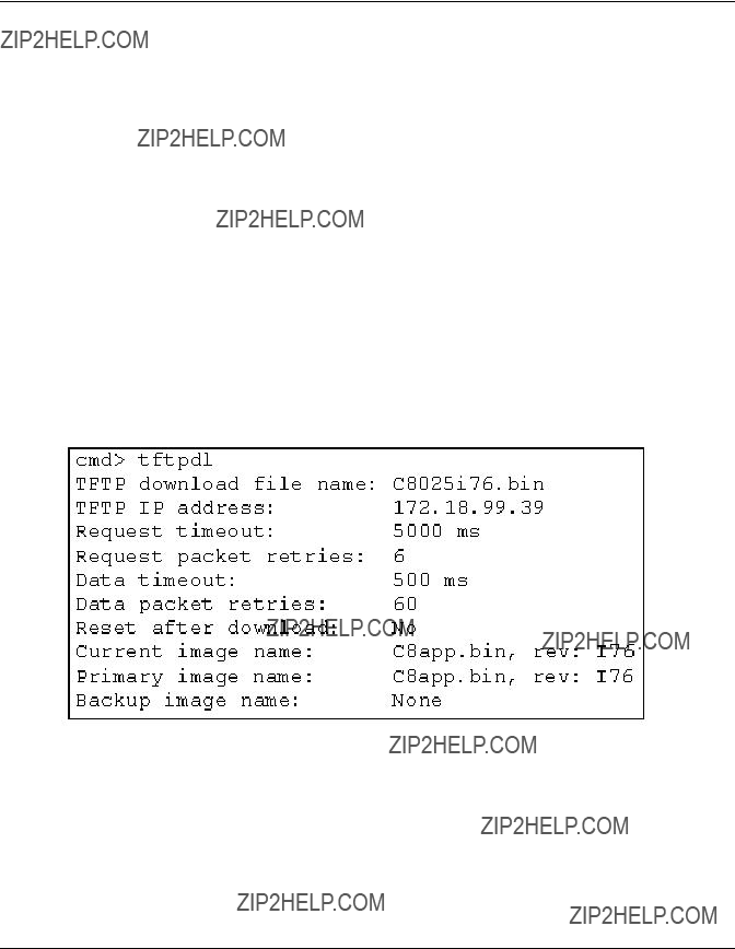
TftpDl
Displays and modifies TFTP download settings for the switch.
Syntax
TftpDl
TftpDl = <file_name>
TftpDl = <ip_address>
TftpDl ReqTimeOut = <req_timeout>
TftpDl ReqRetry = <req_retries>
TftpDl DataTimeout = <data_timeout>
TftpDl DataRetry = <data_retries>
TftpDl Reset = <reset_state>
TftpDl Changeprimary
TftpDl Start
TftpDl??? Displays the TFTP download settings for the switch.
TftpDl = <file_name> ??? Sets the file name of the file to be downloaded from the TFTP server to the text typed in place of the file_name variable.
TftpDl = <ip_address> ??? Sets the IP address of the TFTP server where you want to download a code image from to the number typed in place of the ip_address variable.
TftpDl ReqTimeOut = <req_timeout> ??? Sets the time in milleseconds during which the switch will request the TFTP server to download the image file before giving up to the number typed in place of the req_timeout variable.
TftpDl ReqRetry = <req_retries> ??? Sets the number of attempts the switch will request the server to download the image file before giving up to the number typed in place of the req_retries variable.
TftpDl ReqDataTimeOut = <data_timeout> ??? Sets the time in milleseconds during which the switch will request the TFTP server to download a data packet before giving up to the number typed in place of the data_timeout variable.
TftpDl DataRetry = <data_retries> ??? Sets the number of attempts the switch will request the server to download a data packet before giving up to the number typed in place of the req_retries variable.
Command Line Interface
TftpDl Reset = <reset_state> ??? This setting determines if the switch will automatically reboot after download.
TftpDl ChangePrimary??? Sets the backup image as the primary image.
TftpDl Start??? Starts the download process using the variables configured.
Examples:
Figure

Command Line Interface
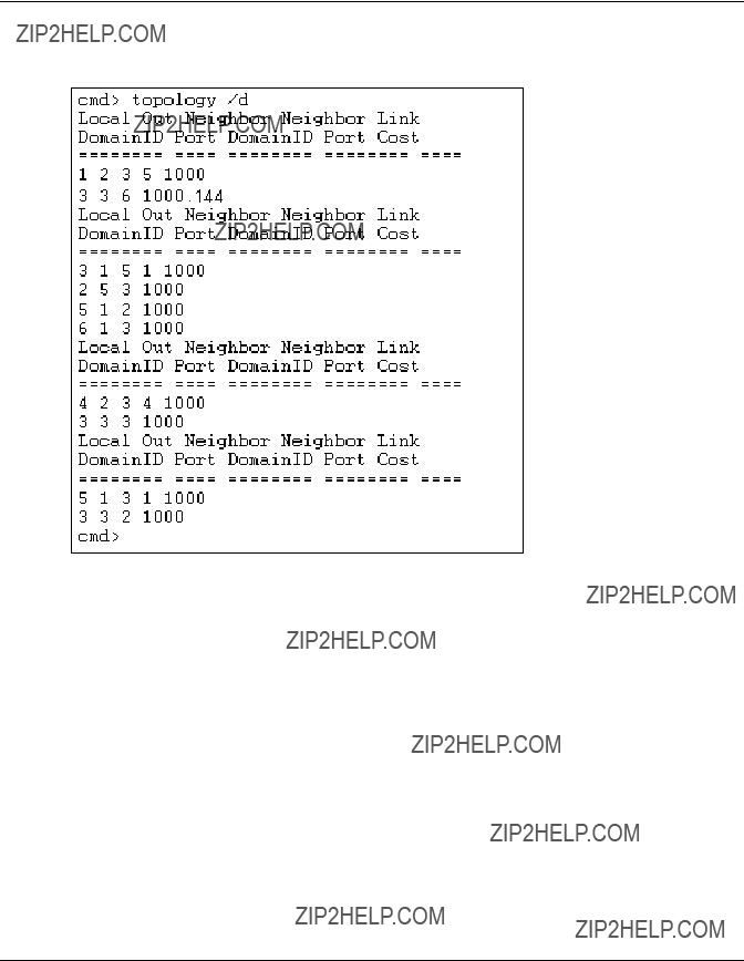
Topology
Displays the topology information for one or all of the switches in the fabric.
Syntax
TOpology
TOpology [/d]
TOpology <domain_Id_number>
Topology??? Displays the information for all of the switches in the network.
Topology /d??? Displays the information for all of the switches in the network without pausing and prompting the user to continue.
Topology <domain_Id_number> ??? Displays the information for the specified switch whose domain ID number is typed in place of the domain_ Id_number variable.
Command Line Interface
Example:
Figure
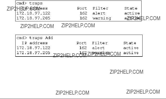
Traps
This command displays and modifies the trap entries. The <ip.port> specifies the trap IP address and trap port address. The format for <ip.port> is ip.ip.ip.port.8 trap entries are supported. Valid range for ???ip??? is 0 ??? 255. Valid range for ???port??? is
Syntax
Traps
Traps Add <ip_address,port_number>
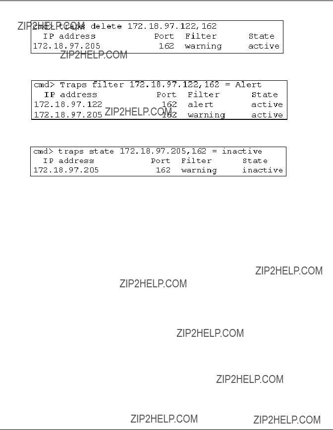
Traps Delete <ip_address,port_number>
Traps Filter <ip_address,port_number>
Traps State <ip_address,port_number>
Command Line Interface
Traps??? Displays trap entry settings.
Traps Add <ip_address,port_number> ??? This command is used to add new trap recipients. Up to eight trap recipients are supported. The command variables are defined as follows:
Traps Delete <ip_address,port_number> ??? This command is used to delete trap recipients from the recipients list. The command variables are defined as fol- lows:
Traps Filter <ip_address,port_number> = <trap_type> ??? This command is used to set the type of traps that you want forwarded to a particular SNMP trap recipient. The command variables are defined as follows:
Command Line Interface
Traps State = <ip_address,port_number> = <trap_state> ??? This command is used to set the state of a particular SNMP trap recipient as active or inactive. The command variables are defined as follows:
Figure
Figure
Command Line Interface
Figure
Figure
Figure
Command Line Interface
Setting up Zoning
Zoning is a function of the MSA Fabric Switch 6 that allows you to create isolated Fibre Channel networks with a limited number of connected devices. By limiting the number of devices in a zone, you can obtain more robust performance and enhance your access protection.
Zoning is compliant with the following standards:
???
???
???
This section describes the zoning functions supported by the MSA Fabric Switch 6. It describes zoning at the individual switch and describes how the merge command functions are used to support zoning across a Fabric.
Zoning Elements
Before performing zoning, you must understand the following zoning elements:
???Zone Members
???Zones
???Zone Sets
CAUTION: Never add a zoned switch to an established fabric that has no zoning. If a switch configured with zoning is added to a fabric that has no configured zoning, the fabric???s HBAs and targets will no longer be able to communicate and the traffic in the fabric will be disrupted. For best results, only add a switch configured with zoning to a fabric configured with same zoning configuration.
Command Line Interface
Zone Members
Zone members are Fibre Channel edge devices that are identified by their World Wide Port Name (WWPN). Any device that you want to include in a zone must be identified as a zone member. While internally the zone members are tracked by their WWPN, you can create a Zone Member Name that acts as an alias for the device. This makes it easier to identify the devices during configuration and operation. The following are examples of Fibre Channel devices that can be named as zone members:
???Servers
???Raid systems
???Disk drives
???Tape libraries
IMPORTANT: The World Wide Node Name (WWNN) of the Fibre Channel device cannot be used to create a zone member.
Zones
Zones are logical entities that represent groupings of zone members. Each zone must assigned a unique zone name when it is defined.
Zone Sets
Zone sets are logical entities that represent groupings of zones. They define a zoning configuration. Each zone set is assigned a unique zone set name when it is defined. The MSA Fabric Switch 6 allows storing of multiple zone sets. However, only one of these zone sets can be active at a time. The other zone sets can be used as backup, trials, or other
Command Line Interface
Naming Rules for Zone Members, Zones, and Zone Sets
Zone member, zone, and zone set names must follow these rules:
???Names must be between 1 and 64 characters long
???Characters used in names must be 7 bit ASCII characters
???The first character of a name must be a letter
???Other characters of the name (any characters besides the first character) can be a letter
???No spaces are allowed in the name
Zoning Limitations for Zone Members, Zones, and Zone Sets
There are zoning limitations for individual switches and fabrics. See Table
Table

Command Line Interface
Using the CLI to Configure Zoning
This section describes how to use the CLI to configure zone members, zones, and zone sets and apply the new or edited zone configurations to the switch.
To ensure uninterrupted operation of the MSA Fabric Switch 6, a
???Stage one: creating the pending table
???Stage two: verifying the zoning configuration in the pending table
???Stage three: writing the pending table to the active table
The zoning configuration procedures are detailed in the following paragraphs and use the following scenario.
Assume the following:
???Server1 needs to access Disk1 exclusively for Operating System boot (OS Boot).
???Server1 needs to access Raid1 for shared storage.
???Server1 needs to access Tape1 for backup.
???Server2 needs to access Disk2 exclusively for Operating System boot.
???Server2 needs to access Raid1 for shared storage.
???Server2 needs to access Tape1 for backup.
Before you begin to configure your zoning, you must first define the zone members, zones, and zone sets that you will need.
Table
Command Line Interface
Table
In this example, the Zone Set
???Web_Zone contains the following Zone Members: Server1, Disk1, RAID1, and Tape1.
???Mail_Zone contains the following Zone Members: Server2, Disk2, RAID1, and Tape1.
Stage one: Creating the Pending Table
Before configuring the zoning, it is helpful to decide on the names you will use for your zone sets, zones, and zone members.
During the configuration, you first create the largest group (zone sets), then create the next largest group (zones), and last create the individual entities (zone members).
After you have created your zone members using their WWPN, you can assign more
Command Line Interface
The steps of stage one include:
???Viewing and clearing the pending table
???Creating the zone set
???Adding zones to the zone set
???Adding zone members to the zones
???Changing the names of the zone members (optional)
???Enabling the pending table zone set
Viewing and Clearing the Pending Table
Start by checking what has already been created:
1. View the pending table.
NOTE: You can also use abbreviated forms of CLI commands. For example, instead of using ???cmd> zone pending,??? you can use ???cmd> zn pn.??? For a list of the CLI abbreviations, type ???help.???
2.Clear the existing pending table. cmd> zone clear
Cleared pending zone configuration.
3.Display the pending table to verify that it was cleared. cmd> zone pending
Zone table is empty.

Command Line Interface
Creating the Zone Set
Create your zone set using the name you already defined (see Table
cmd> zone addzs MIS_NT_CLSTR1_SAN1 Zoneset [MIS_NT_CLSTR1_SAN1] added.
Changes will only take effect after a ???zone write??? command!!
Adding zones to the zone set
Add zones to your zone set using the names you already defined (see Table
cmd> zone addzn MIS_NT_CLSTR1_SAN1 Web_Zone Mail_Zone Zone [Web_Zone] added to zoneset [MIS_NT_CLSR1_SAN1]. Zone [Mail_Zone] added to zoneset [MIS_NT_CLSTR1_SAN1].
Changes will only take effect after a ???zone write??? command!!
Adding zone members to the zones
Add zone members to your zones using the names you have already defined, (see Table
cmd> zn addzm Web_Zone 1000000102421303 2100005004d02f78 Zone member [1000000102421303] added to zone [Web_Zone]. Zone member [2100005004d02f78] added to zone [Web_Zone].
Changes will only take effect after a ???zone write??? command!!
cmd> zn addzm Web_Zone 210000010241ff73 210000010249a7ab Zone member [210000010241ff73] added to zone [Web_Zone]. Zone member [210000010249a7ab] added to zone [Web_Zone].
Changes will only take effect after a ???zone write??? command!!
Command Line Interface
cmd> zn addzm Mail_Zone 100000a0c991a47a 200000600819ae48 Zone member [100000a0c991a47a] added to zone [Mail_Zone]. Zone member [200000600819ae48] added to zone [Mail_Zone].
Changes will only take effect after a ???zone write??? command!!
cmd> zn addzm Mail_Zone 210000010241ff73 210000010249a7ab Zone member [210000010241ff73] already exists, added to zone [Mail_Zone].
Zone member [210000010249a7ab] already exists, added to zone [Mail_Zone].
Changes will only take effect after a ???zone write??? command
Changing the names of the zone members (optional)
To assign a
1. Display the zone members.
cmd> zone pending displayzm
1000000102421303

Command Line Interface
2. Change the zone member name, as illustrated in Table
cmd> zone renzm
Renamed zonemember
Changes will only take effect after a ???zone write??? command!!
cmd> zone renzm
Renamed zonemember
Changes will only take effect after a ???zone write??? command!!
cmd> zone renzm
Renamed zonemember
Changes will only take effect after a ???zone write??? command!!
cmd> zone renzm
Renamed zonemember
Changes will only take effect after a ???zone write??? command!!
cmd> zone renzm
Renamed zonemember
Changes will only take effect after a ???zone write??? command
cmd> zone renzm
Renamed zonemember
Changes will only take effect after a ???zone write??? command!!

Command Line Interface
Enabling the pending table zone set
Enable the zone set in the pending table, so that when it is written to the active table it will be activated:
cmd> zone enable MIS_NT_CLSTR1_SAN1
Zoneset [MIS_NT_CLSTR1_SAN1] enabled.
Stage Two: Verifying the Zoning Configuration in the Pending Table
Make sure that you have the correct configuration by viewing your newly created pending tables. There are four different ways you can confirm that your pending tables are correct.
???Viewing all zone sets, their zones, and zone members in the pending table
???Viewing the zone set in the pending table
???Viewing the zones in the pending table
???Viewing the zone members in the pending table
Viewing the Zone Set, its Zones, and its Zone Members in the pending table
To display all zone sets, zones, and zone members in the pending table:
cmd> zone pending
Active zoneset [MIS_NT_CLSTR1_SAN1] contains 2 zone(s)
zone [Web_Zone] contains 4 member(s)
zone member = [1000000102421303] zone member = [2100005004d02f78] zone member = [210000010241ff73] zone member = [210000010249a7ab]
zone [Mail_Zone] contains 4 member(s)
zone member = [210000010241ff73] zone member = [210000010249a7ab] zone member = [100000a0c991a47a] zone member = [200000600819ae48]
Command Line Interface
Viewing the Zone Set in the pending table
To display zone sets in the pending table:
cmd> zone pending displayzs
Active zoneset [MIS_NT_CLSTR1_SAN1] contains 2 zone(s)
zone = [Web_Zone] zone = [Mail_Zone]
Viewing the Zones in the pending table
To display the zones in the pending table:
cmd> zone pending displayzn
zone [Web_Zone] contains 4 member(s)
zone member = [1000000102421303] zone member = [2100005004d02f78] zone member = [210000010241ff73] zone member = [210000010249a7ab]
zone [Mail_Zone] contains 4 member(s)
zone member = [210000010241ff73] zone member = [210000010249a7ab] zone member = [100000a0c991a47a] zone member = [200000600819ae48]
Viewing the Zone Members in the pending table
To display the zone members in the pending table:
cmd> zone pending displayzm

Command Line Interface
Stage Three: Writing the Pending Table to the Active Table
To complete your zoning configuration, write the newly created pending table to the active zone table.
cmd> zone write
You are about to rewrite active zone configuration with the following pending configuration:
Active zoneset [MIS_NT_CLSTR1_SAN1] contains 2 zone(s)
zone [Web_Zone] contains 4 member(s)
zone member = [1000000102421303] zone member = [2100005004d02f78] zone member = [210000010241ff73] zone member = [210000010249a7ab]
zone [Mail_Zone] contains 4 member(s)
zone member = [210000010241ff73] zone member = [210000010249a7ab] zone member = [100000a0c991a47a] zone member = [200000600819ae48]
Confirm write? [N] y
Zone configuration updated!
To display all local zone sets, zones, and zone members in the active table:
cmd> zone active local
Active zoneset [MIS_NT_CLSTR1_SAN1] contains 2 zone(s)
zone [Web_Zone] contains 4 member(s)
zone member = [1000000102421303] zone member = [2100005004d02f78] zone member = [210000010241ff73] zone member = [210000010249a7ab]
zone [Mail_Zone] contains 4 member(s)
zone member = [210000010241ff73] zone member = [210000010249a7ab] zone member = [100000a0c991a47a] zone member = [200000600819ae48]
Command Line Interface
To display the current
cmd> zone active merged
Active zoneset [MIS_NT_CLSTR1_SAN1] contains 2 zone(s)
zone [Web_Zone] contains 4 member(s)
zone member = [1000000102421303] zone member = [2100005004d02f78] zone member = [210000010241ff73] zone member = [210000010249a7ab]
zone [Mail_Zone] contains 4 member(s)
zone member = [210000010241ff73] zone member = [210000010249a7ab] zone member = [100000a0c991a47a]
zone member = [200000600819ae48]
D
Laser Precautions and
Fibre Channel Cables
Laser Precautions
WARNING: To reduce the risk of injury from laser radiation or damage to the equipment, observe the following precautions:
???Allow only Compaq Authorized Service Technicians to repair the equipment.
???Do not open any panels, operate controls, make adjustments, or perform procedures to a laser device other than those specified herein.
???Do not stare into laser beam when panels are open.
SFP and Fibre Channel Cable Connector Cleaning Considerations
Optics are susceptible to anything that hinders light transmission. Consequently, manufacturers of both
Laser Precautions and Fibre Cables
To minimize the risk of optic contamination on your system, keep the following fibre optic handling guidelines in mind:
???Dust Covers: Dust Covers are provided with all optical components and should be kept in place when not used. Do not throw away the dust covers after initial installation. You may need them to protect optical interconnect areas if reconfiguration is required.
???When to Clean: The best rule of thumb for cleaning fiber optics is common sense. If you have handled fiber optic interconnects and think there may be contamination, clean it. If you need to use a fiber optic interconnect component that is found without the dust covers in place, clean it.
???How to Clean: First, wipe the optics with a
Fibre Channel Cable
The MSA Fabric Switch 6 is intended primarily for use with Shortwave SFPs and
???
???
???
To customize your system with
Laser Precautions and Fibre Cables
If you are using an existing
CAUTION: Make certain the Fibre Channel cables are installed and supported so that no excess weight is placed on the Fibre Channel connectors. This is necessary to prevent damage to the connector and cable and to prevent a cable bend radius less than 3 inches (7.62 cm) at the connector and along the cable length. Excess Fibre Channel cable should be coiled and tied out of the way, being careful not to coil the cable in a tight loop with a bend radius of less than 3 inches (7.62 cm).
E
Updating the Fabric Switch MSA Fabric Switch
6 Management Utility
The MSA Fabric Switch 6 embedded device management program is referred to as the MSA Fabric Switch 6 Management Utility. The baseline software management capabilities for the MSA Fabric Switch 6 can be accessed several different ways. For the latest version of MSA Fabric Switch 6 Management Utility as well as additional upgrading options refer to the Compaq website: www.compaq.com/storageworks, or the MSASW6.txt file on the Modular SAN Array 1000 Support Software
Finding the MSA Fabric Switch 6 Management Utility Version
Number
The current version of the MSA Fabric Switch 6 Management Utility is displayed on the MSA Fabric Switch 6, Device Summary tab. It can also be found on the main menu of the command line interface, labeled ???StorageWorks MSA Fabric Switch 6 Management Utility.??? The MSA Fabric Switch 6 Management Utility contains the embedded agents used by the MSA Fabric Switch 6.
Downloading the Switch Management Utility
Update
There are different methods available for updating the MSA Fabric Switch 6 Management Utility.
Updating the Fabric Switch MSA Fabric Switch 6 Management Utility
Updating the Switch using the Web Browser Interface
To update the switch using the web browser interface under the MSA Fabric Switch 6 Service tab, see Chapter 3, ???MSA Fabric Switch 6 Management Utility.???
Use this screen to set the switch???s parameter and to start the download.
IMPORTANT: The MSA Fabric Switch 6???s IP address and other networking parameters must be properly set for the download to work.
The IP address shown for the TFTP server must be changed to the IP address running the TFTP daemon. The IP address field does not have the ability to resolve host names.
The Management Utility file name must be changed to match the name of the MSA Fabric Switch 6 Management Utility update file. The Management Utility Boot File is automatically extracted from the download file by the MSA Fabric Switch 6 once the transfer is complete. The boot file name needs to be set for a successful update.
Typically, both the timeout and retry parameters do not require resetting unless the network used is overloaded with other traffic.
With all fields completed correctly and the TFTP daemon running, click on ???Download??? to initiate the transfer. The MSA Fabric Switch 6 Management Utility will report the success or failure of the update.
With all parameters completed correctly and the download completed, reset the switch. The update will occur automatically following the reset.
Updating the Switch using the Command Line Interface
The MSA Fabric Switch 6 can also be updated using the command line interface. Use the tftpdl command to set the MSA Fabric Switch 6 TFTP parameters and to start the download process. For information about the tftpdl command, see Appendix C, ???Command Line Interface.???
The IP address shown for the TFTP server must be changed to the IP address running the TFTP daemon. The IP address field does not have the ability to resolve host names.
Updating the Fabric Switch MSA Fabric Switch 6 Management Utility
The download file name must be changed to match the name of the MSA Fabric Switch 6 Management Utility update. The boot file is automatically extracted from the download file by the StorageWorks MSA Fabric Switch 6 once the transfer is complete. The boot file name needs to be set for a successful update. This will be provided along with the download file at the Compaq website: www.compaq.com/storageworks.
Typically, both the timeout and retry parameters do not require resetting unless the network used is overloaded with other traffic.
Once the transfer is initiated, the MSA Fabric Switch 6 Management Utility package number is compared with the package already resident in the MSA Fabric Switch 6. If the MSA Fabric Switch 6 Management Utility being downloaded is newer and appears compatible, the download status will be set to ???in progress??? and remains so until the transfer is complete. Once the MSA Fabric Switch 6 Management Utility is updated, the system reboots itself to initialize the new MSA Fabric Switch 6 Management Utility and changes the status to ???complete.???
If the MSA Fabric Switch 6 Management Utility being downloaded is older than the present or incompatible with the system, the MSA Fabric Switch 6 stops the transfer and sets the download status to ???rejected due to incompatible package versions.??? With all parameters completed correctly and the download completed, reset the switch. The update will occur automatically following the reset.
Updating the Fabric Switch MSA Fabric Switch 6 Management Utility
Updating the Switch using the Boot Menu
The MSA Fabric Switch 6 can also be updated using the Boot Menu. The Boot Menu is accessible immediately after the MSA Fabric Switch 6 is powered up or reset. The Boot Menu permits you to configure the networking parameters necessary to download new MSA Fabric Switch 6 Management Utility with TFTP even if the current utility program is not functioning. To access the Boot Menu, connect to the switch directly using a null modem cable and use a program such as HyperTerminal in Windows. The default terminal settings are 38400/8N1/No Flow Control. With the null modem connected and HyperTerminal running, reset the switch. To access the Boot Menu, you must press the Enter key when prompted; this occurs within the first few seconds following the reset.
The IP address shown for the TFTP server IP address (4.) must be changed to the IP address running the TFTP daemon. The IP address field does not have the ability to resolve host names.
The download file name must be changed to match the name of the MSA Fabric Switch 6 Management Utility update. The file is automatically extracted from the download file by the MSA Fabric Switch 6 once the transfer is complete.
Typically, both the timeout and retry parameters do not require resetting unless the network used is overloaded with other traffic.
With all parameters completed correctly and the download completed, choose ???0??? to exit the boot menu and reset the switch. The update will occur automatically following the reset.

A
AC, power cord
overview of
B
boot straps, using
C
cables
15 meter
fibre channel, troubleshooting
troubleshooting
CLI
Index
logout screen, illustrated
main menu, illustrated
Command Line Interface (CLI) overview of
commands, CLI beacon
Index
community names restoring
Compaq authorized reseller xi Compaq website xi configuration
connecting a terminal to
D
E
electrostatic discharge precautions
transporting products
ESD See electrostatic discharge Ethernet
F
fabric switch, configuration
backup/restore tab
CLI beacon on command
CLI help command
CLI hwcfg command
CLI netcfg command
CLI portctl cost command
CLI portctl heartbeat command
CLI portstatus command
command
CLI porttp command
CLI SNMP con command
CLI swstate command ports data
CLI temp command
CLI traps delete command
Index
firmware tab
main help session screen
installed
network parameters menu
port button screen
port info/port control tab screen
port information screen
port summary tab screen
set IP address menu
SFP tab operational display screen
second part
SFP tab vendor display screen
stat counter reset view screen
switch control tab
system information panel
full duplex communications
G
gateway address
MSA Fabric Switch 6 configuration
grounding methods
specifications
H
heel straps, using
CLI
command line interface
I
illustrations
backup/restore tab
CLI beacon on command
CLI hwcfg command
CLI netcfg command
CLI portctl command ports data
CLI portctl heartbeat command

Index
Index
M
main board, MSA Fabric Switch 6
overview of
change password
management options menu
network parameters, illustrated
MSA Fabric Switch 6 MSA Fabric Switch 6
Compaq supported SFPs
Ethernet indicators
fault indicator
full duplex
global status indicator
network parameters menu
reading indicators
MSA Fabric Switch 6 Management Utility, features
MSA Fabric Switch 6, configuration
N
network
parameters menu, MSA Fabric Switch 6 configuration
P
parameters tftp
parts
proper handling
passwords changing
port
bypass, automatic
prerequisites
MSA Fabric Switch 6 installation
R

Index
S
serial
communication problems
serial port settings baud rate
bits per second
stop bits
community names
SFPs
cleaning
transporting products in
MSA Fabric Switch 6 configuration
Switch Management Utility downloading update
updating using the Boot menu
switching engine, MSA Fabric Switch 6
symbols on equipment vii
system, preventing electrostatic damage to
T
tables
backup/restore tab
command line interface summary
default serial port settings
Ethernet indicators
port control panel
port summary window
switch info window
technical support xi telephone numbers xi temperature problems
monitoring
serial vs telnet
configuration of the switch
tftp
changing IP address
server IP address
conductive field service type
Index
troubleshooting cabling
connection problems
MSA Fabric Switch 6
temperature control problems
U
user interfaces, listed
V
versions, Switch Management Utility, finding