ProLiant 1850R Servers
Maintenance and Service Guide
First Edition (July 1998)
Part Number
Spare Part Number
Compaq Computer Corporation
ProLiant 1850R Servers
Maintenance and Service Guide
First Edition (July 1998)
Part Number
Spare Part Number
Compaq Computer Corporation
Notice
The information in this publication is subject to change without notice.
COMPAQ COMPUTER CORPORATION SHALL NOT BE LIABLE FOR TECHNICAL OR
EDITORIAL ERRORS OR OMISSIONS CONTAINED HEREIN, NOR FOR INCIDENTAL
OR CONSEQUENTIAL DAMAGES RESULTING FROM THE FURNISHING,
PERFORMANCE, OR USE OF THIS MATERIAL. THIS INFORMATION IS PROVIDED
???AS IS??? AND COMPAQ COMPUTER CORPORATION DISCLAIMS ANY WARRANTIES,
EXPRESS, IMPLIED OR STATUTORY AND EXPRESSLY DISCLAIMS THE IMPLIED
WARRANTIES OF MERCHANTABILITY, FITNESS FOR PARTICULAR PURPOSE,
GOOD TITLE AND AGAINST INFRINGEMENT.
This publication contains information protected by copyright. No part of this publication may be photocopied or reproduced in any form without prior written consent from Compaq Computer Corporation.
?? 1998 Compaq Computer Corporation. All rights reserved. Printed in the U.S.A.
The software described in this guide is furnished under a license agreement or nondisclosure agreement. The software may be used or copied only in accordance with the terms of the agreement.
Compaq, Deskpro, Fastart, Compaq Insight Manager, Systempro, Systempro/LT, ProLiant, ROMPaq, QVision, SmartStart, NetFlex, QuickFind, PaqFax, ProSignia, registered United States Patent and Trademark Office.
Netelligent, Systempro/XL, SoftPaq, QuickBlank, QuickLock are trademarks and/or service marks of Compaq Computer Corporation.
Microsoft,
Other product names mentioned herein may be trademarks and/or registered trademarks of their respective companies.
Compaq ProLiant 1850R Servers Maintenance and Service Guide

Compaq ProLiant 1850R Servers Maintenance and Service Guide

iv
Chapter 3
Diagnostic Tools

Index
Compaq ProLiant 1850R Servers Maintenance and Service Guide

vii
About This Guide
This Maintenance and Service Guide is a troubleshooting guide that can be used for reference when servicing ProLiant 1850R Servers.
WARNING: To reduce the risk of personal injury from electrical shock and hazardous energy levels, only authorized service technicians should attempt to repair this equipment. Improper repairs could create conditions that are hazardous.
IMPORTANT: The installation of options and servicing of this product should be performed by individuals that are knowledgeable of the procedures, precautions, and hazards associated with equipment containing hazardous energy circuits.
Symbols in Text
These symbols may be found in the text of this guide. They have the following meanings.
WARNING: Indicates that failure to follow directions in the warning could result in bodily harm or loss of life.
CAUTION: Indicates that failure to follow directions could result in damage to equipment or loss of information.
IMPORTANT: Presents clarifying information or specific instructions.
NOTE: Presents commentary, sidelights, or interesting points of information.
Compaq Technician Notes
WARNING: Only authorized technicians trained by Compaq should attempt to repair this equipment. All troubleshooting and repair procedures are detailed to allow only subassembly/module level repair. Because of the complexity of the individual boards and subassemblies, no one should attempt to make repairs at the component level or to make modifications to any printed wiring board. Improper repairs can create a safety hazard. Any indications of component replacement or printed wiring board modifications may void any warranty.
WARNING: To reduce the risk of personal injury from electrical shock and hazardous energy levels, do not exceed the level of repair specified in these procedures. Because of the complexity of the individual boards and subassemblies, do not attempt to make repairs at the component level or to make modifications to any printed wiring board. Improper repairs could create conditions that
Compaq ProLiant 1850R Servers Maintenance and Service Guide

viii About This Guide
are hazardous.

ix
WARNING: To reduce the risk of electric shock or damage to the equipment:
???If the system has multiple power supplies, disconnect power from the system by unplugging all power cords from the power supplies.
???Do not disable the power cord grounding plug. The grounding plug is an important safety feature.
???Plug the power cord into a grounded (earthed) electrical outlet that is easily accessible at all times.
CAUTION: To properly ventilate your system, you must provide at least 12 inches (30.5 cm) of clearance at the front and back of the computer.
CAUTION: The computer is designed to be electrically grounded. To ensure proper operation, plug the AC power cord into a properly grounded AC outlet only.
CAUTION: To properly ventilate your system, you must provide at least 12 inches (30.5 cm) of clearance at the front and back of the computer.
IMPORTANT: Any indication of repair at the component level or modification of a printed wiring board may void any warranty.
Where to Go for Additional Help
Major sources of additional information are listed below
Other Information Sources
In addition to this guide, the following information sources are available:
???User Documentation
???Compaq Service Quick Reference Guide
???Service Training Guides
???Compaq Service Advisories and Bulletins
???Compaq QuickFind
???Compaq Insight Manager
???Compaq Download Facility: Call
Compaq ProLiant 1850R Servers Maintenance and Service Guide

x About This Guide
Telephone Numbers
For the name of your nearest Compaq Authorized Reseller:
In the United States, call
In Canada, call
For Compaq technical support:
In the United States and Canada, call
For Compaq technical support phone numbers outside the United States and Canada, visit the Compaq Website at: http://www.compaq.com
Elsewhere, call one of the numbers listed in the following table:
Compaq Worldwide Technical Support Telephone Numbers
continued

xi
Compaq Worldwide Technical Support Telephone Numbers continued
Compaq ProLiant 1850R Servers Maintenance and Service Guide
Chapter 1
Illustrated Parts Catalog
This chapter provides the illustrated parts breakdown and a spare parts list for the ProLiant 1850R Servers. See Table
Compaq ProLiant 1850R Servers Maintenance and Service Guide

Mechanical Parts Exploded View
2
3
9
27e
27g
1
26
12
Figure

System Components
Exploded View
9
6
13
17
7
12
4
27c
21
5
22
4
11
22
Figure
Compaq ProLiant 1850R Servers Maintenance and Service Guide

Spare Parts List
Table
Spare Parts List
continued
Spare Parts List - ProLiant 1850R Servers continued
a)
b)
a)28 inch F1,
b)Two Device, F1, SCSI Cable Assembly
c)Diskette Drive Cable Assembly
d)Eight Inch, F1, CD Data Cable Assembly
MISCELLANEOUS
a)Fan Guard Power Supply *
b)Fan Cover *
c)Wireform Fan Guard
d)
e)Processor Retention Brackets *
f)Fan Mounting Bracket *
g)Slot Cover
e) Card Guide
continued
Compaq ProLiant 1850R Servers Maintenance and Service Guide
Spare Parts List - ProLiant 1850R Servers continued
continued

Spare Parts List - ProLiant 1850R Servers continued
* Not Shown
Compaq ProLiant 1850R Servers Maintenance and Service Guide

Chapter 2
Removal and Replacement
Procedures
This chapter provides
The following tools are recommended:
???Torx
???Torx
???Nut driver
???From the Compaq SmartStart and Support Software CD:
???System Configuration Utility software
???Drive Array Advanced Diagnostics software
???Diagnostics software
Compaq ProLiant 1850R Servers Maintenance and Service Guide

Electrostatic Discharge Information
A discharge of static electricity can damage
???Transport products in
???Keep
???Cover workstations with approved
???Keep work area free of
???Make sure you are always properly grounded when touching a
???Avoid touching pins, leads, or circuitry.
???Always place drives
???Use conductive field service tools.
Symbols in Equipment
WARNING: Any surface or area of the equipment marked with these symbols indicates the presence of a hot surface or hot component. If this surface is contacted, the potential for injury exists. To reduce risk of injury from a hot component, allow the surface to cool before touching.
WARNING: Any surface or area of the equipment marked with these symbols indicates the presence of electrical shock hazards. The enclosed area contains no operator serviceable parts. To reduce risk of injury from electrical shock hazards, do not open this enclosure.
WARNING: Any
WARNING: This label or equivalent is located on the CLASS 1 LASER PRODUCTsurface of your
the product is classified as a CLASS 1 LASER
PRODUCT.

WARNING: To reduce the risk of electrical shock or damage to the equipment, disconnect power from the server by unplugging all power cords from either the electrical outlet or the server.
Compaq ProLiant 1850R Servers Maintenance and Service Guide
Preparation Procedures
Before beginning any of the removal and replacement procedures:
1.Turn OFF the server and any peripheral devices.
2.Disconnect the AC power cord from the AC outlet, then from the server.
3.Disconnect all external peripheral devices from the server.
4.For most removal and replacement procedures, you must remove the server from the rack and place it on a sturdy table or workbench. Refer to the ProLiant 1850R Setup and Installation Guide.
WARNING: To reduce the risk of personal injury, do not attempt to remove the server from the rack by yourself. A minimum of two people are required to remove the server from the rack.
WARNING: Because the rack allows you to stack computer components on a vertical rather than horizontal plane, you must take precautions to provide for rack stability and safety. It is important that you follow these precautions to provide for rack stability and safety, and to protect both personnel and property. Heed all cautions and warnings throughout the installation instructions that came with the server.
CAUTION: Electrostatic discharge can damage electronic components. Be sure you are properly grounded before beginning any installation procedure. See the section titled ???Electrostatic Discharge??? for more information.

Rack Warnings
WARNING: Always load the heaviest item first and load the rack from the bottom up. This makes the rack
WARNING: To reduce the risk of personal injury, fire, or damage to the equipment, do not overload the AC supply branch circuit that provides power to
the rack.
WARNING: To reduce the risk of personal injury or damage to the equipment, the bottom stabilizers on the equipment must be fully extended. Be sure that the equipment is properly supported/braced when installing options and cards.
WARNING: To reduce the risk of personal injury or damage to the equipment, at least two people are needed to safely unload the rack from the pallet. An empty 42U rack weighs 253 lb (115 kg), is over seven ft (2.1m) tall, and may become unstable when being moved on its casters. Do not stand in front of the rack as it rolls down the ramp from the pallet; handle it from the sides.
WARNING: A rack may become unstable if more than one component is extended for any reason. To reduce the risk of personal injury, be sure that the rack is adequately stabilized before extending a component outside the rack, and extend only one component at a time.
WARNING: Before beginning work on the rack, be sure that the leveling jacks are extended to the floor, that the full weight of the rack rests on the level floor, and that either stabilizers are installed or multiple racks are coupled for stability.
Compaq ProLiant 1850R Servers Maintenance and Service Guide

Server Warnings and Precautions
WARNING: To reduce the risk of personal injury from hot surfaces, allow the internal system components to cool before touching.
CAUTION: Protect the server from power fluctuations and temporary interruptions with a regulating uninterruptible power supply (UPS). This device protects the hardware from damage caused by power surges and voltage spikes and keeps the system in operation during a power failure.
CAUTION: The ProLiant 1850R Server must always be operated with system unit covers on. Proper cooling will not be achieved if the system unit covers
are removed.
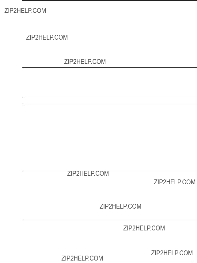
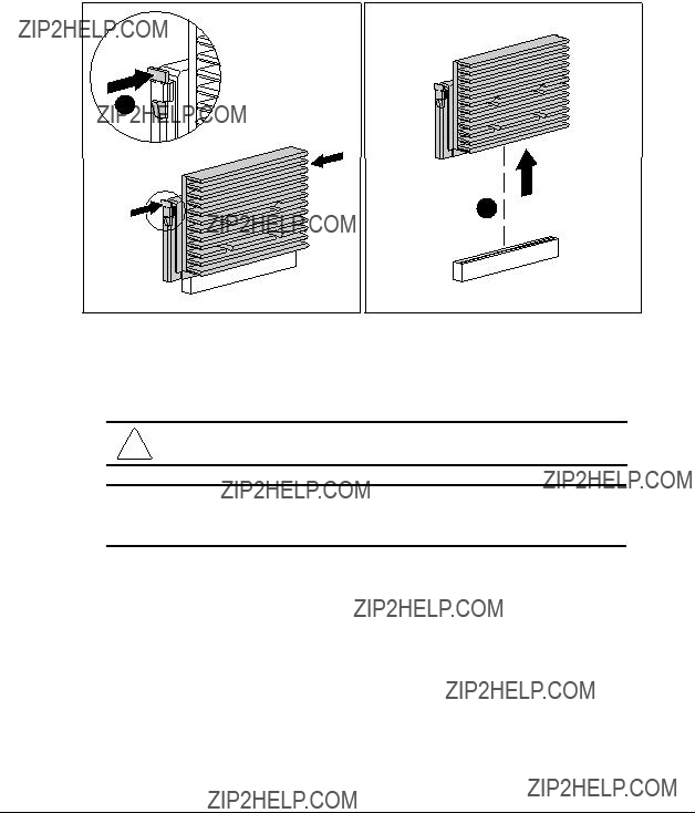
Server Cover
Remove the server cover to gain access to drive bays, expansion slots, boards, and switches inside the server. To remove the server cover:
1.Perform the preparation procedures. See page
2.Loosen the three captive thumbscrews on the
3.Use the grip slot to slide the cover toward the rear of the unit about 1 inch (2.5 cm).
4.Move the server cover to the right side of the unit.
5.Lift off the server cover.
Figure
Reverse steps 1 through 5 to replace the server cover.
Compaq ProLiant 1850R Servers Maintenance and Service Guide
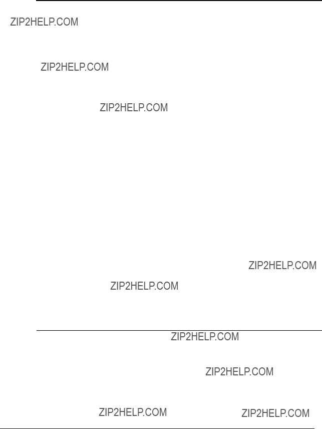
To remove the
WARNING: Before removing the
1.Perform the preparation procedures. See page
2.Loosen the five thumbscrews on the bezel.
3.Remove the eight
4.Remove the
Figure
Reverse steps 1 through 4 to replace the

Power/Standby Switch with LEDs
To remove the power/standby switch with LEDs:
1.Perform the preparation procedures. See page
2.Remove the server cover. See page
3.Remove the diskette drive. See page
4.Remove the two female connectors 1.
5.Remove the LEDs from the holders in the power/standby switch 2.
3
1
5
2
4
Figure
6.Push inward slightly at points 3 and 4 to release the power/standby switch from the bezel.
7.Remove the switch parts from the bezel 5.
Reverse steps 1 through 7 to replace the power/standby switch with LEDs.
NOTE: The LEDs have one flat side, which must be correctly oriented before insertion into
the holder.
Compaq ProLiant 1850R Servers Maintenance and Service Guide
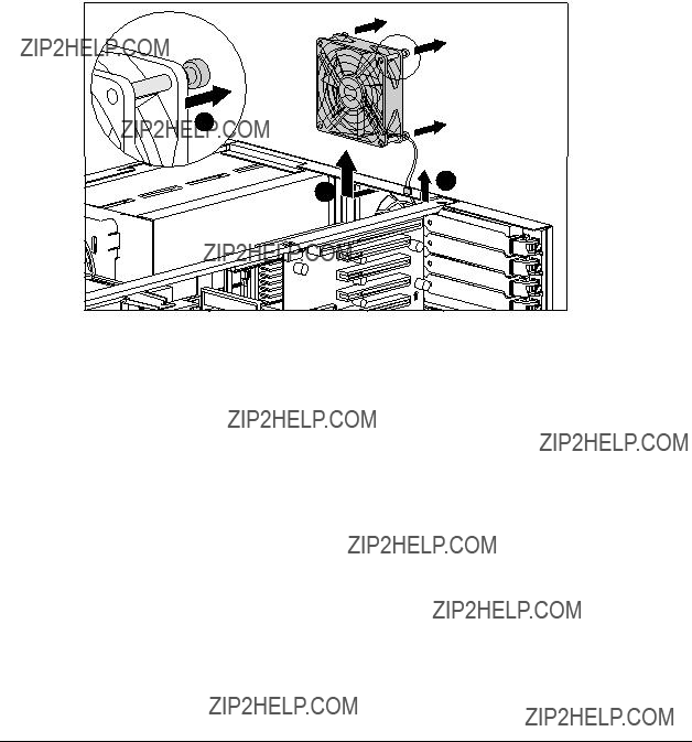
Rear Fan
To remove the rear fan:
1.Perform the preparation procedures. See page
2.Remove the server cover. See page
3.Unplug the rear fan from the system board 1.
4.Remove the four retention pins 2 attaching the fan assembly to the chassis.
5.Remove the rear fan 3.
2
1
3
Figure
Reverse steps 1 through 5 to replace the rear fan.

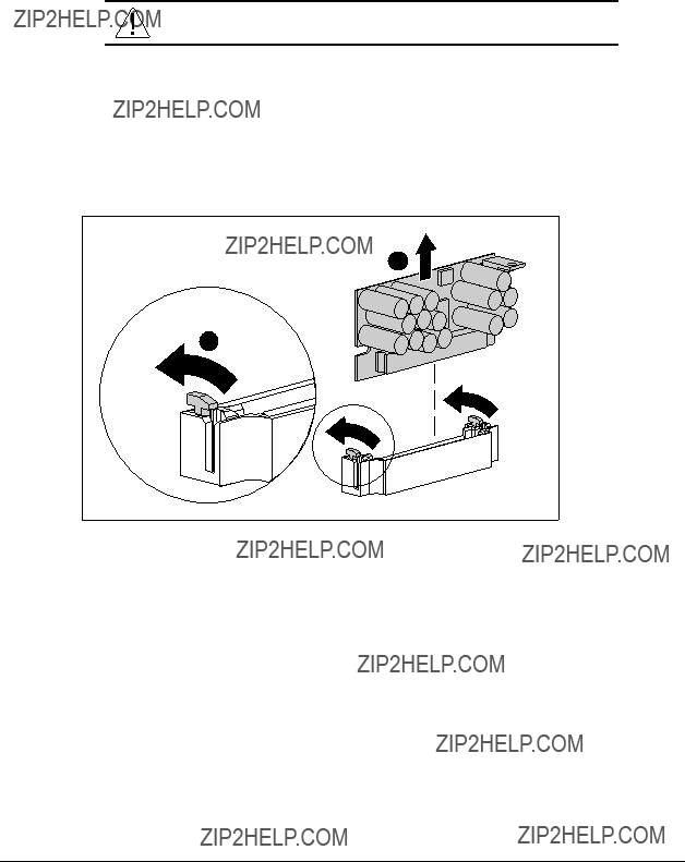
Drive Cage Fan and Bracket
To remove the drive cage fan and bracket:
1.Perform the preparation procedures. See page
2.Remove the server cover. See page
3.Disconnect the data and power cables connected to the
4.Unplug the fan from the power supply.
5.Remove the three
6.Pull the fan and bracket away from the drive cage.
Figure
Reverse steps 1 through 6 to replace the drive cage fan and bracket.
Compaq ProLiant 1850R Servers Maintenance and Service Guide
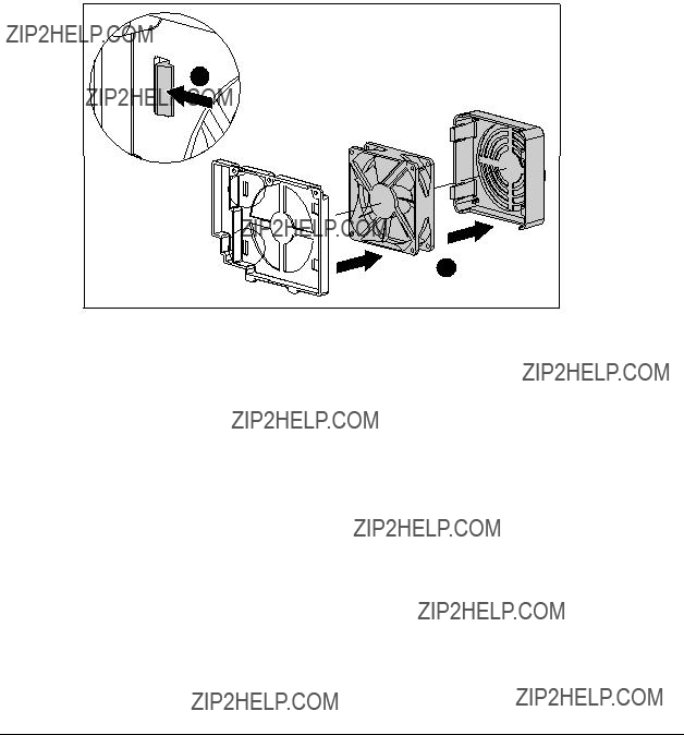
Drive Cage Fan Bracket
To disassemble the drive cage fan bracket:
1.Perform the preparation procedures. See page
2.Remove the server cover. See page
3.Remove the drive cage fan and bracket. See page
4.Push in on the two
5.Remove the bracket and fan guard from the fan 2.
1
2
Figure
Reverse steps 1 through 5 to assemble the drive cage fan bracket.
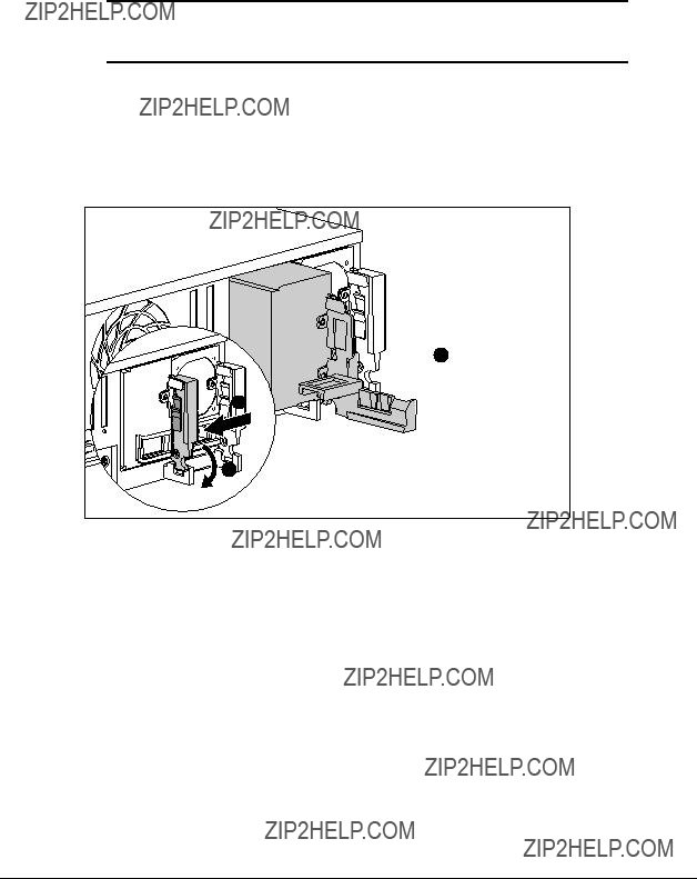
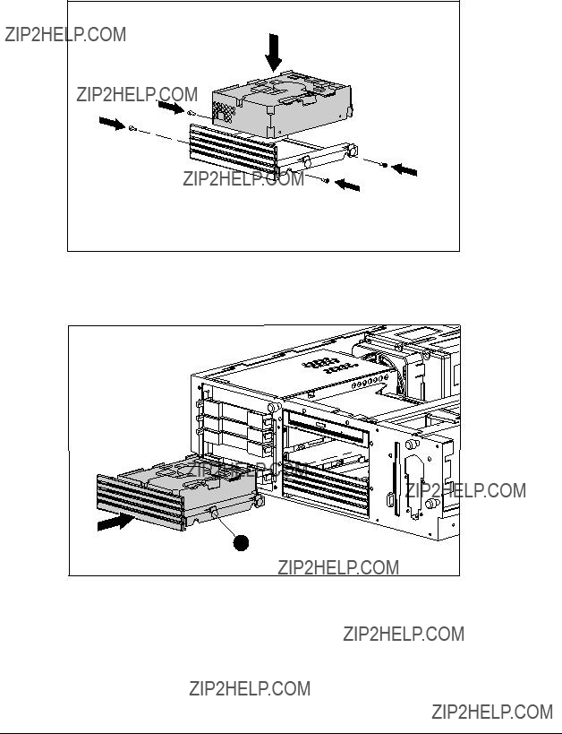
The
IMPORTANT: When using a single power supply module, it must populate the outer bay. Both bays can be populated for redundant power supply capability.
1.Perform the preparation procedures. See page
2.Push in the
3.Pull the tab out until it opens 2.
4.Pull the power supply blank out the back of the chassis 3.
 3
3
1
2
Figure
Compaq ProLiant 1850R Servers Maintenance and Service Guide
5.Install the
6.Push the tab 2 in until it locks.
1
2
Figure

Mass Storage Devices
Compaq ProLiant 1850R Servers can house up to 7 mass storage devices, including:
???Preinstalled
???Two available
???Preinstalled 24X Max
???Up to three
Drive Installation Guidelines
When adding SCSI hard drives to the ProLiant 1850R Servers, observe the following guidelines:
???A maximum of seven SCSI devices per controller may be added.
???Each SCSI drive must have a unique address.
???SCSI addresses (IDs) are automatically determined for drives installed in the
???Compaq
???The
???Supported Compaq SCSI options are not terminated.
The following chart provides the SCSI ID jumper settings for Compaq SCSI hard drives.
Table
SCSI ID Settings
* NOTE: OFF = jumper removed
Compaq ProLiant 1850R Servers Maintenance and Service Guide

ProLiant 1850R Drives
This section describes the drive bay positions, removal and replacement procedures, and hard drive installation for parts unique to the ProLiant 1850R Server.
Drive Bays
The ProLiant 1850R Server has five drive bays for internal mass storage devices. SCSI devices can be installed in drive bay 3, or attached to the external
CAUTION: The ProLiant 1850R server does not support the installation of IDE or EIDE fixed disk drives.
Figure
Table
ProLiant 1850R Description of Drive Bays
A
B
124X Max

Compaq ProLiant 1850R Servers Maintenance and Service Guide
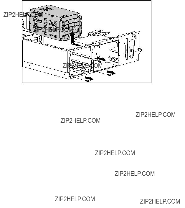
Drive Cage
To remove the drive cage:
1.Perform the preparation procedures. See page
2.Remove the three Torx
3.Disconnect the SCSI cable and power cable from the drive backplane board.
4.Pull the drive cage back and up to remove it from the server.
Figure
Reverse steps 1 through 4 to replace the drive cage.

24X Max
To remove the 24X Max
1.Perform the preparation procedures. See page
2.Remove the server cover. See page
3.Remove the diskette drive. See page
4.Remove the retaining screw securing the 24X Max
5.Pull the 24X Max
Figure
Reverse steps 1 through 5 to replace the 24X Max
Compaq ProLiant 1850R Servers Maintenance and Service Guide

Installing a
To install a
1.Perform the preparation procedures. See page
2.Remove the server cover. See page
3.Remove the diskette drive. See page
4.Remove the 24X Max
5.Remove the
2
1
Figure
6.Attach the
Figure
7.Install the drive assembly into the drive bay. Make sure the guide screw 1 lines up with the guide slot in the removable media drive cage.
1
Figure
Compaq ProLiant 1850R Servers Maintenance and Service Guide

8.Connect the cables drive power and signal cables.
Figure
9.Replace the diskette drive.
10.Replace the server cover.

Installing a 1/2 Height Tape Drive or
Drive in
Bay A or B
ProLiant 1850R Servers have two bays, bay A and bay B, for removable media. Bays A and B can accomodate two
1.Perform the preparation procedures. See page
2.Remove the server cover. See page
3.Remove the
4.Remove the
5.Remove the removable media tray.
2
1
Figure
Compaq ProLiant 1850R Servers Maintenance and Service Guide
6.Insert the drive 1 into drive bay A or B.
7.Tighten the two screws 2 securing the drive in the drive cage.
1
2
Figure
8.Attach the IDE and power cables to the 1/2 height tape drive.
9.Connect the drive power and signal cables.
Figure
10. Replace the

24X Max
To remove the 24X Max
1.Perform the preparation procedures. See page
2.Remove the server cover. See page
3.Remove the diskette drive. See page
4.Disconnect the IDE cable and power cable from the adapter board 1.
5.Remove the two
6.Pull the adapter board straight out the back of the 24X Max
2 3
1
Figure
Reverse steps 1 through 6 to replace the 24X Max
Compaq ProLiant 1850R Servers Maintenance and Service Guide

Installing a Hard Drive in Bay 0
The drive cage supports three
1.Perform the preparation procedures. See page
2.Insert the drive in the drive cage 1, sliding the hard drive guides into the mounting slots.
3.Close the connector levers 2.
Figure

Diskette Drive
To remove the diskette drive:
1.Perform the preparation procedures. See page
2.Remove the server cover. See page
3.Disconnect the power and data cables from the diskette drive (if installed).
4.Remove one
5.Slide the diskette drive back, then away from the front bezel until it stops.
NOTE: Make sure the diskette eject lever clears the bezel when removing the diskette drive. Slide the diskette drive straight back from the front of the unit.
6.Pull the diskette drive out 2 and lift it from the chassis 3.
Figure
Reverse steps 1 through 6 to replace the diskette drive.
NOTE: Make sure the diskette eject lever clears the bezel. Slide the diskette drive toward the back, then push it to the front of the unit.
External Storage Devices
You can connect optional mass storage devices to the ProLiant 1850R by using the external
Compaq ProLiant 1850R Servers Maintenance and Service Guide

Cable Routing Diagrams
CAUTION: When routing cables, always make sure that the cables are not in a position where they will be pinched or crimped.
Diskette Drive Cable
Figure
Figure

Figure
Internal SCSI Cable Attached to Array
Controller
Figure
Compaq ProLiant 1850R Servers Maintenance and Service Guide

Riser Board and Brace
To remove the riser board and brace:
1.Perform the preparation procedures. See page
2.Remove the server cover. See page
3.Remove all expansion boards.
4.Loosen the two captive screws securing the riser board and brace 1.
5.Lift the riser board and brace out of the unit 2.
Figure
Reverse steps 1 through 5 to replace the riser board and brace.
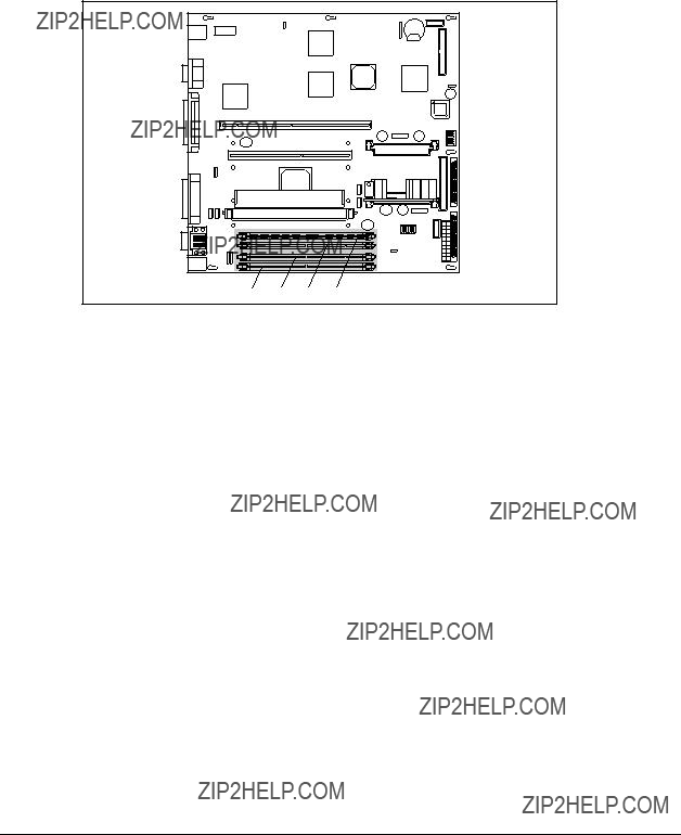
Memory
The ProLiant 1850R ships standard with a minimum 64 MB of Synchronous DRAM (SDRAM) DIMM memory, installed in slot 1. Memory can be expanded to a maximum of 1 GB. Install SDRAM DIMM modules one at a time in the proper slots. See Figure
Figure
Compaq ProLiant 1850R Servers Maintenance and Service Guide
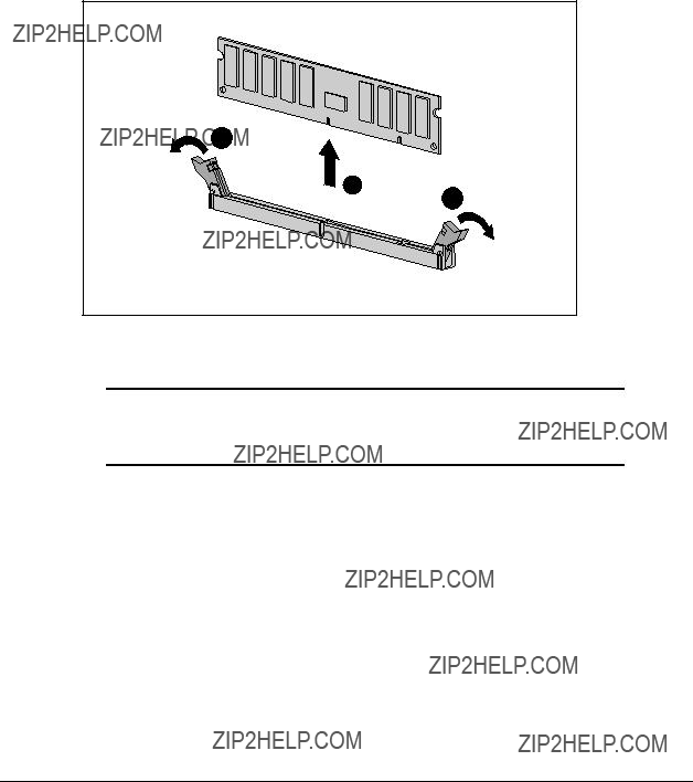
To remove a SDRAM DIMM:
1.Perform the preparation procedures. See page
2.Remove the server cover. See page
3.Remove any expansion boards above the SDRAM DIMM slot.
4.Press both SDRAM DIMM slot latches outward 1.
5.Lift out the SDRAM DIMM 2.
1
2
1
Figure
Reverse steps 1 through 5 to replace a SDRAM DIMM.
IMPORTANT: A memory module can be installed one way only. Be sure to match the key slots on the module with the tabs on the memory slot. Push the module down into the slot, ensuring that the module is fully inserted and properly seated.
The following guidelines MUST be followed when installing or replacing memory:
???Use only
???SDRAM DIMMs must be 100 MHz.
???Use Compaq SDRAM DIMMs only.
???SDRAM DIMMs must all be the same speed, and rated 100 MHz.
The recommended order of SDRAM DIMM installation is:
???Second SDRAM DIMM in slot 2 (J15)
???Third SDRAM DIMM in slot 3 (J16)
???Fourth SDRAM DIMM in slot 4 (J19)
Any combination of SDRAM DIMMs can be used.
Table
Examples of SDRAM DIMM Upgrade Combinations
Compaq ProLiant 1850R Servers Maintenance and Service Guide
Processor
ProLiant 1850R Servers can support up to two processors. Figure
Figure
Table
Processor and Processor Power Module Locations
3Intel Pentium II Processor
4Intel Pentium II Processor
To remove either of the processors:
1.Perform the preparation procedures. See page
2.Remove the server cover. See page
3.Push in the retaining clips on each side of the processor 1.
4.Pull out the processor 2.
1
2
Figure
Reverse steps 1 through 4 to replace the processor. Use the System Configuration Utility to reconfigure your system if you are replacing a faulty processor. See Chapter 3 for more information.
CAUTION: Processors on the same processor board MUST be installed in matched frequency.
IMPORTANT: The processor is keyed to be sure correct alignment. Align the pattern of pins in the processor with the pattern of holes in the socket. The pins and holes will not line up if the processor is turned the wrong way.
Compaq ProLiant 1850R Servers Maintenance and Service Guide
Processor Power Module
Every processor comes with a processor power module
WARNING: To reduce the risk of personal injury from hot surfaces, allow the internal system components to cool before touching.
To remove a processor power module:
1.Perform the preparation procedures. See page
2.Remove the server cover. See page
3.Press the socket latches 1 outward with your index fingers until the latches snap open.
4.As the socket latches open, the module comes out of the socket 2.
2
1
Figure
Reverse steps 1 through 4 to install a processor power module. The processor power module is keyed to ensure correct alignment. Use the System Configuration Utility to reconfigure the server. See Chapter 3 for more information.
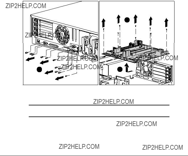
System Board
To remove the system board:
1.Perform the preparation procedures. See page
2.Remove the server cover. See page
3.Remove all expansion boards.
4.Remove the Riser board and brace. See page
5.Disconnect the cables both in and out of the chassis. See page
6.Remove any SDRAM DIMMs. See page
7.Remove the processor(s). See page
8.Remove the processor power module(s). See page
9.Remove the ten nuts and one screw 1 securing the connector plate.
10.Remove the eight
11.Slide the system board back, then lift it from the chassis 3.
2
Figure
Reverse steps 1 through 11 to replace the system board.
IMPORTANT: Make sure the system board seats properly over the chassis retaining guides, then slide it back into place.
Compaq ProLiant 1850R Servers Maintenance and Service Guide

External Replacement Battery
ProLiant 1850R Servers contain one battery that might require the installation of an external replacement on the system board.
System Board Battery
If the server no longer automatically displays the correct date and time, you may need to replace the battery that provides power to the
WARNING: The system board contains a clock/CMOS lithium battery, which can explode if mistreated. The battery is soldered in place and can not be removed. Do not abuse or disassemble. Use only replacement batteries supplied by Compaq Computer Corporation.
To install an external battery on the system board:
1.Perform the preparation procedures. See page
2.Remove the server cover. See page
3.Locate the battery header as depicted in the following illustration.
4.Change the jumper on header E2 from pins
Figure

IMPORTANT: When a jumper is on header E2 / pins
IMPORTANT: The system board contains a Lithium Manganese Dioxide or Lithium Vanadium Pentoxide battery that should not be disposed of together with the general waste. In order to forward it to recycling or proper disposal, please use the public collection system or return it to Compaq, or your authorized Compaq Partners.
5.Remove the backing from the adhesive on the
6.Place the battery and the
7.Plug the battery connector onto pins
Figure
8.Place the sticker included with your battery kit on the back of your server above the power connector.
9.Run the Compaq System Configuration Utility to reconfigure the system. See Chapter 3 for more information.
Compaq ProLiant 1850R Servers Maintenance and Service Guide

Chapter 3
Diagnostic Tools
This chapter describes software and firmware diagnostic tools available for all Compaq server products. The sections in this chapter are:
???Default Configuration
???Utility Access
???
???Diagnostics Software
???Drive Array Advanced Diagnostics (DAAD)
???Integrated Management Log
???Rapid Recovery Services
???Remote Service Features
???ROMPaq
???Compaq Insight Manager
Compaq ProLiant 1850R Servers Maintenance and Service Guide

Default Configuration
When the system is first powered on, the system ROM detects the unconfigured state of the hardware and provides default configuration settings for most devices. By providing this initialization, the system can run Diagnostics and other software applications before running the normal SmartStart and System Configuration programs.
Default Configuration Messages
IMPORTANT: If you chose to format and partition your boot drive before running SmartStart and the System Configuration programs, this may prohibit creating a System Partition and the
If you insert a System Configuration, Diagnostics, or SmartStart CD in the
Utilities Access
The Compaq SmartStart and Support Software CD contains the SmartStart program and many of the Compaq utilities needed to maintain your system, including:
???System Configuration Utility
???Array Configuration Utility
???Drive Array Advanced Diagnostics Utility
???ROMPaq Firmware Upgrade Utilities
CAUTION: Do not select the Erase Utility when running the SmartStart and Support Software CD. This will result in data loss to the entire system.
There are several ways to access these utilities:
???Run the utilities on the system partition.
If the system was installed using SmartStart, the Compaq utilities will automatically be available on the system partition. The system partition could also have been created during a manual system installation.

To run the utilities on the system partition, boot the system and press F10 when you see ???Press F10 for system partition utilities.??? Then select the utilities from the menu.
???System Configuration Utility is available under the System Configuration menu.
???Array Configuration Utility is available under the System Configuration menu.
???Drive Array Advanced Diagnostics Utility is available under the Diagnostics and Utilities menu.
???ROMPaq Firmware Upgrade Utility is available under the Diagnostics and Utilities menu.
???Run the utilities from diskette.
You can also run the utilities from their individual diskettes. If you have a utility diskette newer than the version on the SmartStart and Support Software CD, use that diskette.
You can also create a diskette version of the utility from the SmartStart and Support Software CD. To create diskette versions of the utilities from the CD:
1.Boot the Compaq SmartStart and Support Software CD.
2.From the Compaq System Utilities screen, select Create Support Software ??? Next.
3.Select the diskette you would like to create from the list, then follow the instructions on the screen.
???Run the utilities from the Compaq SmartStart and Support Software CD.
IMPORTANT: Only the System Configuration Utility and the Array Configuration Utility can be executed from the Compaq SmartStart and Support Software CD. All other utilities must be executed only from the system partition or from diskette.
To run these utilities directly from the Compaq SmartStart and Support Software CD:
1.Start the Compaq SmartStart and Support Software CD.
2.From the Compaq System Utilities screen, select the utility you wish to run, and select Next.
???To execute the System Configuration Utility, select Run System Configuration Utility.
???To execute the Array Configuration Utility, select Run Array Configuration Utility.
Compaq ProLiant 1850R Servers Maintenance and Service Guide

POST is a series of diagnostic tests that run automatically on Compaq computers when the system is turned on. POST checks the following assemblies to ensure that the computer system is functioning properly:
???Processors
???Keyboard
???Power supply
???System board
???Memory
???Memory expansion boards
???Controllers
???Diskette drives
???Hard drives
If POST finds an error in the system, an audible and/or visual message appears. If an error code appears on the screen during POST or after resetting the system, follow the instructions in Table
The Action column lists the steps needed to correct the problem. After completing each step, run the Diagnostics program. If the error code reappears, perform the next step, then run the Diagnostics program again. Repeat this procedure until the error is corrected.
Table
POST Error Messages
Compaq ProLiant 1850R Servers Maintenance and Service Guide

POST Error Messages continued

Compaq ProLiant 1850R Servers Maintenance and Service Guide

POST Error Messages continued
and yy have corresponding bit set.
The speed of the memory modules must be 60 ns. Verify the speed of the memory modules installed and replace.

Compaq ProLiant 1850R Servers Maintenance and Service Guide

POST Error Messages continued

Compaq ProLiant 1850R Servers Maintenance and Service Guide

POST Error Messages continued

Compaq ProLiant 1850R Servers Maintenance and Service Guide

POST Error Messages continued
Use
Compaq ProLiant 1850R Servers Maintenance and Service Guide
POST Error Messages continued
Run the latest Systems ROMPaq Utility to upgrade your System ROMs.

Remove or reconfigure conflicting ISA cards, especially any cards that are not recognized by the System Configuration Utility. Try reprogramming the
Compaq ProLiant 1850R Servers Maintenance and Service Guide

POST Error Messages continued

Compaq ProLiant 1850R Servers Maintenance and Service Guide

POST Error Messages continued

Compaq ProLiant 1850R Servers Maintenance and Service Guide
POST Error Messages continued
*NOTE: The 1788 error message might also be displayed inadvertently due to a bad power cable connection to the drive or by noise on the data cable. If this message was due to a bad power cable connection, but not because of an incorrect drive replacement, repair the connection and press F2.
If this message was not due to a bad power cable connection, and no drive replacement took place, this could indicate noise on the data cable. Check cable for proper routing.
Continued

POST Error Messages continued
Compaq ProLiant 1850R Servers Maintenance and Service Guide

POST Error Messages continued
Match the Array Accelerator to the correct drive array, or run the System Configuration Utility to clear the data in the Array Accelerator.
Compaq ProLiant 1850R Servers Maintenance and Service Guide

POST Error Messages continued

Diagnostics Software
Tables
When you select Diagnostics and Utilities from the System Configuration Utility main menu, the utility prompts you to test, inspect, upgrade, and diagnose the server.
Diagnostics and Utilities are located on the system partition on the hard drive and must be accessed when a system configuration error is detected during the
The following options are available from the Diagnostics and Utilities menu:
???Test Computer
???Inspect Computer
???Upgrade Firmware
???Remote Utilities
???Diagnose Drive Array
Diagnostic error codes are generated when the Diagnostics software recognizes a problem. These error codes, listed in tables
In each case, the Recommended Action column lists the steps necessary to correct the problem. After completing each step, run the Diagnostics program to verify whether the error condition has been corrected. If the error code reappears, perform the next step, then run the Diagnostics program again. Follow this procedure until the Diagnostics program no longer detects an error condition.
If you encounter an error condition, complete the following steps before starting problem isolation procedures:
1.Be certain proper ventilation exists. The computer should have approximately 12 inches (30.5 cm) clearance at the front and back of the system unit.
2.Turn off the computer and peripheral devices.
3.Disconnect any peripheral devices not required for testing. Do not disconnect the printer if you want to test it or use it to log error messages.
4.Turn on the computer.
5.Delete the
6.Disable the
Compaq ProLiant 1850R Servers Maintenance and Service Guide

7.Install a loopback plug (Part Number
8.Run the latest version of Diagnostics.
Running Diagnostics
There are two ways to access the utilities:
???From the System Partition.
???From diskette. A diskette can be created from the SmartStart CD.
1.Accessing the utilities from the system partition:
2.Reboot the server by pressing the Ctrl+Alt+Delete keys.
Press F10 when the following prompt appears at the top of the screen during POST.
Press ???F10??? for System Partition Utilities.
IMPORTANT: The text appears for only two seconds. If you do not press F10 during this time, you must reboot the server.
3. From the System Configuration Main Menu, select Diagnostics and Utilities.
If there are errors detected in your Server Health Log, the Diagnostics Utility automatically displays the following screen message:
CAUTION: Errors have been detected in you Server Health Log. Diags will now identify your system hardware.
1.Press the Enter key to continue.
2.After a short pause, the Server Health Log menu displays with a list of system errors. If there is more than one error, press the Space Bar to select the error you want to correct. Press Enter.
3.The Diagnostics Utility prompts you and suggests corrective action.

Primary Processor Test Error Codes
The 100 series of Diagnostic error codes identifies failures with processor and system board functions. Corrective action may require replacement of system boards or processor assemblies (either processor boards or system boards that include the processor).
Table
Primary Processor Test Error Codes
Compaq ProLiant 1850R Servers Maintenance and Service Guide

Memory Test Error Codes
The 200 series of Diagnostic error codes identifies failures with the memory subsystem. Corrective action may require replacement of the memory expansion board, the memory modules, or the processor assembly.
Table
Memory Test Error Codes
Keyboard Test Error Codes
The 300 series of Diagnostic error codes identifies failures with keyboard and system board functions. Corrective action may require replacement of a keyboard or the system board assembly.
Table
Keyboard Test Error Codes
The following steps apply to error codes
through
1.Check the keyboard connection. If disconnected, turn off the computer and connect the keyboard
and retest.
2.Replace the keyboard and retest.
3.Replace the system board and retest.
Parallel Printer Test Error Codes
The 400 series of Diagnostic error codes identifies failures with parallel printer interface card or system board functions. Corrective action may require replacement of the serial/parallel interface board or the system board assembly.
Table
Parallel Printer Test Error Codes
The following steps apply to error codes
through
1.Connect the printer and retest.
2.Check the power to the printer and retest.
3.Install the loopback connector and retest.
4.Check the switch on the Serial/Parallel Interface board (if applicable) and retest.
5.Replace the Serial/Parallel Interface board (if applicable) and retest.
6.Replace the system board and retest.
Compaq ProLiant 1850R Servers Maintenance and Service Guide
Video Display Unit Test Error Codes
The 500 series of Diagnostic error codes identifies failures with video or system board functions. Corrective action may require replacement of a video board or the system board assembly.
Table
Video Display Unit Test Error Codes
The following steps apply to error codes
1.Replace the monitor and retest.
2.Replace the Advanced VGA board
and retest.
3.Replace the system board and retest.

Diskette Drive Test Error Codes
The 600 series of Diagnostic error codes identifies failures with diskette, diskette drive, or system board functions. Corrective action may require replacement of a diskette, a diskette drive, or the system board assembly.
Table
Diskette Drive Test Error Codes
Monochrome Video Board Test Error Codes
The 800 series of Diagnostic error codes identifies failures with monochrome video boards or system board functions. Corrective action may require replacement of a monochrome video board or the system board assembly.
Table
Monochrome Video Board Test Error Codes
Compaq ProLiant 1850R Servers Maintenance and Service Guide

Serial Test Error Codes
The 1100 series of Diagnostic error codes identifies failures with serial/parallel interface board or system board functions. Corrective action may require replacement of the serial/parallel interface board or the system board assembly.
Table
Serial Test Error Codes
The following steps apply to error codes
and
1.Check the switch settings on the Serial/Parallel Interface board (if applicable) and retest.
2.Replace the Serial/Parallel Interface board (if applicable) and retest.
3.Replace the system board and retest.
Modem Communications Test Error Codes
The 1200 series of Diagnostic error codes identifies failures with the modem(s). Corrective action may require replacement of the modem(s).
Table
Modem Communications Test Error Codes
The following steps apply to error codes
1.Refer to the modem documentation for correct setup procedures and retest.
2.Check the modem line and retest.
3.Replace the modem and retest.
Fixed Disk Drive Test Error Codes
The 1700 series of Diagnostic error codes identifies failures with fixed disk drives, fixed disk drive controller boards, fixed disk drive cabling, and system board functions. Corrective action may require replacement of fixed disk drive cables, fixed disk drive controller boards, fixed disks, or the system board assembly. If your system uses a drive array controller, see the section for Drive Array Advanced Diagnostics (DAAD).
Table
Fixed Disk Drive Test Error Codes
Compaq ProLiant 1850R Servers Maintenance and Service Guide

Tape Drive Test Error Codes
The 1900 series of Diagnostic error codes identifies failures with tape cartridges, tape drives, tape drive cabling, adapter boards, or the system board assembly. Corrective action may require replacement of tape cartridges, tape drive cabling, adapter boards, tape drives, or the system board assembly.
Table
Tape Drive Test Error Codes
Advanced VGA Board Test Error Codes
The 2400 series of Diagnostic error codes identifies failures with video boards, monitors, or the system board assembly. Corrective action may require replacement of a monitor, video boards, or the system board assembly.
Table
Advanced VGA Board Test Error Codes
The following steps apply to error codes
1.Run the System Configuration Utility.
2.Replace the monitor and retest.
3.Replace the Advanced VGA board or other video board and retest.
4.Replace the system board and retest.
continued
Compaq ProLiant 1850R Servers Maintenance and Service Guide

Advanced VGA Board Test Error Codes continued
ECG/VGC ROM checksum test failed. ECG/VGC attribute test failed.
ECG/VGC 640 x 200 graphics mode test failed.
ECG/VGC 640 x 350
ECG/VGC 640 x 350
ECG/VGC monochrome text mode test failed.
ECG/VGC monochrome graphics mode test failed.
640 x 480 graphics test failure.
320 x 200 graphics
Advanced VGA Controller test failed.
Advanced VGA Data Path Test.
Advanced VGA DAC Test.
The following steps apply to error codes
1.Run Setup.
2.Replace the system board and retest.

Controller
Test Error Codes
The 6000 series of Diagnostic error codes identifies failures with
Table
Test Error Codes
The following steps apply to error codes
1.Check the controller installation in the EISA slot.
2.Check the interrupt type and number setting.
3.Check the media connection at the controller and Multistation Access Unit (MAU).
4.Check the media speed (4/16 ) and type Unshielded Twisted Pair/Shielded Twisted Pair (UTP/STP) settings.
5.Check the MAU, cabling, or other network components.
6.Replace the controller.
Compaq ProLiant 1850R Servers Maintenance and Service Guide

Compaq Network Interface Cards
Test Error Codes
The 6000 series of Diagnostic error codes identifies failures with Compaq Network
Interface Cards.
Table
Compaq Network Interface Cards
Test Error Codes
The following steps apply to error codes
through
1.Check the controller installation in the EISA slot.
2.Check the interrupt type and number setting.
3.Check the media connection at the controller and Multistation Access Unit (MAU).
4.Check the media speed (4/16 ) and type Unshielded Twisted Pair/Shielded Twisted Pair (UTP/STP) settings.
5.Check the MAU, cabling, or other network components.
6.Replace the controller.

SCSI Fixed Disk Drive Test Error Codes
The 6500 series of Diagnostic error codes identifies failures with SCSI fixed disk drives, SCSI fixed disk drive controller boards, SCSI fixed disk drive cabling, and system board functions. Corrective action may require replacement of fixed disk drive cables, fixed disk drive controllers, fixed disks, or the system board assembly. If your system uses a drive array controller, see the section for Drive Array Advanced Diagnostics (DAAD).
Table
SCSI Fixed Disk Drive Test Error Codes
SCSI Disk ID drive types test failed. SCSI Disk Unconditional Format test failed.
SCSI Disk Read Test Failed. SCSI Disk SA/Media test failed. SCSI Disk Erase tape test failed.
SCSI Disk Random Read test failed. Media load/unload test failed.
The following steps apply to error codes
through
1.Run the System Configuration Utility and verify the drive type.
2.Replace the SCSI disk drive signal and power cables and retest.
3.Replace the SCSI controller and retest.
4.Replace the SCSI disk drive and retest.
5.Replace the system board and retest.
SCSI/IDE
The 6600 series of Diagnostic error codes identifies failures with the
Table
SCSI/IDE
The following steps apply to error codes
1.Replace the
2.Check and/or replace the signal cable and retest.
3.Check the switch settings on the adapter board
(if applicable).
4.Replace the SCSI controller (if applicable)
and retest.
5.Replace the
6.Replace the system board and retest.
Compaq ProLiant 1850R Servers Maintenance and Service Guide

SCSI Tape Drive Test Error Codes
The 6700 series of Diagnostic error codes identifies failures with tape cartridges, tape drives, media changers, tape drive cabling, adapter boards, or the system board assembly. Corrective action may require replacement of a tape cartridge, tape drive, media changer, tape drive cabling, adapter board, or the system board assembly.
Table
SCSI Tape Drive Test Error Codes
The following steps apply to error codes
1.Run the System Configuration Utility and verify the drive type.
2.Replace the SCSI Tape drive signal and power cables and retest.
3.Replace the SCSI controller and retest.
4.Replace the SCSI Tape drive and retest.
5.Replace the system board and retest.
Server Manager/R Board Test Error Codes
The 7000 series of Diagnostic error codes identifies failures with the Server Manager/R board. Corrective action may require replacement of the Server Manager/R board, the Integrated
Table
Server Manager/R Board Test Error Codes
For error codes
and retest.
continued
Server Manager/R Board Test Error Codes continued
Pointing Device Interface Test Error Codes
The 8600 Diagnostic error codes identifies failures with the pointing device (mouse, trackball, etc.) or the system board assembly. Corrective action may require replacement of the pointing device or the system board assembly.
Table
Pointing Device Interface Test Error Codes
The following steps apply for the
1.Replace with a working pointing device and retest.
2.Replace the system board and retest.
Compaq ProLiant 1850R Servers Maintenance and Service Guide

Drive Array Advanced Diagnostics (DAAD)
Drive Array Advanced Diagnostics (DAAD) is a
The two main functions of DAAD are:
???Collecting all possible information about array controllers in the system
???Offering a list of all detected problems
NOTE: Refer to the Drive Array Advanced Diagnostics User Guide, found on the SmartStart CD, for complete details and procedures about this diagnostic tool.
DAAD works by issuing multiple commands to the array controllers to determine if a problem exists. This data can then be saved to a file and, in severe situations, this file can be sent to Compaq for analysis. In most cases, DAAD will provide enough information to initiate problem resolution immediately.
NOTE: DAAD does not write to the drives or destroy data. It does not change or remove configuration information.
Starting DAAD
To start DAAD:
1.Insert the DAAD diskette into drive A.
2.Reboot the system - OR - if you are at the DOS prompt, enter the following:
A:DAAD
NOTE: To generate a DAAD report without starting the interactive portion of the utility, enter the following at the DOS prompt: DAAD filename
where filename is the name of the file or report.
A dialog box is displayed, indicating the version of DAAD installed. Press the Enter (or ???C???) key to continue, or press the Esc (or ???E???) key to exit without continuing.
1.If you continue, a Please Wait panel is displayed, indicating that DAAD is identifying the system parameters.
DAAD gathers all the information it can from all of the array controllers in the system. The time it takes to gather this information depends on the size of your system.
A second Please Wait panel may be displayed to indicate that the utility is identifying the ROM version of an array controller in the system.
CAUTION: Do not cycle the power; the utility must perform low- level operations that, if interrupted, could cause the controller to revert to a previous level of firmware if the firmware was soft- upgraded.
When the information gathering process is complete, the main DAAD screen is displayed.
Compaq ProLiant 1850R Servers Maintenance and Service Guide

Table
Table
DAAD Diagnostic Messages
Install array accelerator board on array controller. If an array accelerator board is installed, check for proper seating on the array controller board. You may need to run the System Configuration Utility and disable the array accelerator board to get this message off the screen.
If there are many parity errors, you may need to replace the array accelerator board.
If there are many parity errors, you may need to replace the array accelerator board.
If there are many parity errors, you may need to replace the array accelerator board.

continued
Compaq ProLiant 1850R Servers Maintenance and Service Guide

DAAD Diagnostic Messages continued
Fix the problem with the drive(s). Then the controller will be able to write the dirty data to the drives and posted write operations will be restored.
Replacement of the cache should be considered. If cache replacement is not done the remaining cache lines should continue to operate properly.
Check to be sure that the array accelerator is properly seated. If the error continues you may need to replace the array

continued
Compaq ProLiant 1850R Servers Maintenance and Service Guide

DAAD Diagnostic Messages continued
Nothing needs to be done. Normal operations
should continue.

Compaq ProLiant 1850R Servers Maintenance and Service Guide

DAAD Diagnostic Messages continued
Run the latest version of System Configuration Utility to configure the controller and nonvolatile RAM.
To recognize the array accelerator board, run the System Configuration Utility.
Run the System Configuration Utility to configure the nonvolatile RAM.
Run Options ROMPaq to upgrade the controller to the latest firmware revision.

Replace the controller as soon as possible.
continued
Compaq ProLiant 1850R Servers Maintenance and Service Guide

DAAD Diagnostic Messages continued
Check for other errors
Compaq ProLiant 1850R Servers Maintenance and Service Guide

DAAD Diagnostic Messages continued

continued
Compaq ProLiant 1850R Servers Maintenance and Service Guide

DAAD Diagnostic Messages continued
Run the System Configuration Utility to configure the controller and nonvolatile RAM.
Operate the system without the array accelerator board until the drive rebuild completes.

Compaq ProLiant 1850R Servers Maintenance and Service Guide
DAAD Diagnostic Messages continued
Logical Drive X A physical drive has a cabling status = problem.
LOOSE
CABLE
DETECTED
Turn the system off and attempt to reattach the cable onto the drive. If this does not work, replace the cable.
Logical Drive X A physical drive in this logical
When booting up the system, select the "F1 - rebuild drive" option to rebuild the replaced drive.
Check the fans and the operating environment.
Check the fans and the operating environment.

continued
Compaq ProLiant 1850R Servers Maintenance and Service Guide

DAAD Diagnostic Messages continued

Compaq ProLiant 1850R Servers Maintenance and Service Guide

DAAD Diagnostic Messages continued
The drive may need to be replaced. Run the Compaq Diagnostics Utility to determine if the drive has been initialized and the threshold violation warrants
drive replacement.
Obtain the latest version of DAAD.
Check the other error messages for an indication of
the problem.
Replace the drive with a Compaq supplied drive, or restore the drive???s operating parameters.
Check the diagnosis screen for other error messages. Run the System Configuration Utility to update the system configuration.
Integrated Management Log
On servers supporting the Integrated Management Display, Compaq Integrated Management Log (IML) replaces the Critical Error Log and Correctable Memory Logs. It records system events and stores them in an easily viewable form. It marks each event with a
Events listed in the Integrated Management Log are categorized as one of four event severity levels:
???Status - indicates that the message is informational only.
???Repaired - indicates that corrective action has been taken.
???Caution - indicates a
???Critical - indicates a component failure.
The Integrated Management Log requires Compaq Operating
Multiple Ways of Viewing the Log
You can view an event in the IML in several ways:
???On the Integrated Management Display
???From within Compaq Insight Manager
???From within Compaq Survey Utility
???From within IML Management Utility
Integrated Management Display
The Integrated Management Display is a Liquid Crystal Display (LCD) panel that presents information directly at the server, assisting in diagnosing and servicing the server without a keyboard and monitor.
Compaq Insight Manager
Compaq Insight Manager is a server management tool providing
Compaq ProLiant 1850R Servers Maintenance and Service Guide

Viewing the Event List
1.From Compaq Insight Manager, select the appropriate server, then select View Device Data. The selected server is displayed with buttons around its perimeter.
2.Select the Recovery button.
3.Select Integrated Management Log.
4.If a failed component has been replaced, select the event from the list, then select Mark Repaired.
Printing the Event List
NOTE: You can only view the list from the Recovery/Integrated
Management Log screen as described above.
1.From the Insight Manager, select the appropriate server.
2.Select the Configuration button.
3.Select the Recovery button.
4.Select Print.
Compaq Survey Utility
The Compaq Survey Utility is a serviceability tool available from Windows NT and Novell NetWare that delivers
After running the Compaq Survey Utility, you can view the IML by loading the output of the utility (typically called ???survey.txt???) into a text viewer such as Notepad. The event list follows the system slot information. Once you have opened the text file, you can print it using the print feature of the viewer.
Compaq IML Management Utility
The Compaq IML Management Utility is a

List of Events
The event list displays the affected components and the associated error messages. Though the same basic information is displayed, the format of the list may be different, depending on how you are viewing it: on the Integrated Management Display, from within Compaq Insight Manager, the IML management utility, or from within the Compaq Survey Utility. An example of the format of an event as displayed on the Integrated Management Display is as follows:
**001 of 010**
03/19/1997 12:54 PM
FAN INSERTED Main System Location:
System Board Fan ID: 03
**END OF EVENT**
Compaq ProLiant 1850R Servers Maintenance and Service Guide

Event Messages continued

Automatic Operating System Shutdown Initiated Due to Overheat Condition
Fatal Exception (Number X, Cause)
Compaq ProLiant 1850R Servers Maintenance and Service Guide

Rapid Recovery Services
Compaq servers provide rapid recovery services for diagnosing and recovering from errors. These tools are available for local and remote diagnosis and recovery.
Rapid recovery means fast identification and resolution of complex faults. The Rapid Recovery Engine and Insight Management Agents notify the system administrator when a failure occurs, ensuring that the server experiences minimal downtime. You enable these features through the System Configuration Utility. These integrated server management features are:
???Automatic Server
???Server Health Logs (on servers not supporting Integrated Management Logs)
???Storage Fault Recovery Tracking
???Storage Automatic Reconstruction
???Network Interface Fault Recovery Tracking
???Memory Fault Recovery Tracking (with option upgrade kit)
These are discussed in more detail on the Systems Reference Library CD (SRL).
Automatic Server
Automatic Server
You can tell
You can also configure
To configure
1.Execute the System Configuration Utility.
2.Select View and Edit Details.
3.Set the software error recovery status to Enabled.
4.Set the software error recovery

The available recovery features are:
???Software Error Recovery ??? automatically restarts the server after a
???Environmental Recovery ??? allows the server to restart when temperature, fan, or AC power conditions return to normal
Unattended Recovery
For unattended recovery,
???Logs the error information to the IML
???Resets the server
???Pages you (if a modem is present and you selected paging)
???Tries to restart the operating system. Often the server restarts successfully, making unattended recovery the ideal choice for remote locations where trained service personnel are not immediately available.
To use this level of
Attended Recovery
For attended recovery,
???Logs the error information to the IML
???Resets the server
???Pages you (if a modem is present and you selected Paging)
???Starts Compaq Utilities from the hard drive
???Enables remote access
During system configuration, these utilities are placed on the system utilities partition of the hard drive.
If you have configured for
If you have configured the Compaq Utilities for network access, you can access the utilities over the network. You can use Compaq Insight Manager for
Compaq ProLiant 1850R Servers Maintenance and Service Guide

Hardware Requirements
To use this level of
???Compaq modem or optional Hayes modem
???System Configuration Utility and Diagnostics Utility installed on the system partition of the hard drive
???
You can also run Compaq Utilities remotely over an IPX or IP network using the
Network feature:
???To use Compaq Utilities on an IPX network, you must have Compaq Insight Manager
2.0or later or an NVT (Novell Virtual Terminal) Terminal Emulator with VT100 or ANSI terminal capabilities.
???To use Compaq Utilities on an IP network, you must have Compaq Insight Manager
2.10or later, or a Telnet Terminal Emulator with VT100 or ANSI capabilities.
If you are notified that
You can configure
as possible.
When you enable
When you enable
You can configure your server to start Compaq Utilities in four different ways:
???Without remote console support; for example, to run Compaq Utilities from the server console only
???With remote console support using modems for
???With remote console support using a modem to dial a predetermined telephone number
???With remote console support through a network connection (IP or IPX)

Compaq Integrated Remote Console
The standard Compaq Integrated Remote Console performs a wide range of configuration activities. Some of the console???s features include
???Accessible using ANSI terminal
???Operates independently of the operating system
???Provides for remote server reboot
???Provides access to system configuration
???Uses
For more information, see the Integrated Remote Console User Guide, that shipped with your server.
IMPORTANT: Before configuring
Compaq Health Driver
The Compaq Health Driver continually resets the
For remote and
The Compaq Health Driver is independent of the
Before
Compaq ProLiant 1850R Servers Maintenance and Service Guide

The following
Hardware/Software error occurs
|
Error records in the Critical Error Log, or the Integrated Management Log, depending on your server configuration.
|
Operating System halts normal operation
|
ASR Timer expires
|
Server is reset
|
If a modem is installed and paging is enabled, the Server Failure Notification pager alert is sent to the Server Administrator
Booting into Compaq Utilities
When you enable
If
If Network Status is enabled, the appropriate network support software is loaded, depending on the network protocol, IP or IPX. This allows remote access via the network.
IMPORTANT: Compaq Utilities are loaded from a specially created system partition on the hard drive. This partition was configured during server configuration.
You can access the server and view the Server Health Logs (in servers not supporting the IML) remotely by modem,
You can also enable
The System Configuration Utility settings should resemble the settings in the following table when you enable
Compaq ProLiant 1850R Servers Maintenance and Service Guide

Table
Compaq System Configuration Utility Pager Settings
for Booting into Compaq Utilities
continued

Compaq System Configuration Utility Pager Settings for Booting into Compaq Utilities continued
Compaq ProLiant 1850R Servers Maintenance and Service Guide


Compaq System Configuration Utility Pager Settings for Booting into Compaq Utilities continued
If you configure the server to boot into Compaq Utilities, it prepares for remote communications. You can remotely run Diagnostics software, Inspect Utility, or System Configuration Utility using a workstation running terminal emulation software, such as Compaq Insight Manager or PC Anywhere.
Booting into the Operating System
When you enable
IMPORTANT: When you enable
During the recovery process, the
Your System Configuration Utility setting should resemble the following when you enable ASR to restart into the operating system:
Compaq ProLiant 1850R Servers Maintenance and Service Guide

The standard Compaq password features function differently during
During
To maintain system security, set the server to boot in Network Server Mode (an option in the System Configuration Utility). This option ensures that the server keyboard is locked until you enter the Keyboard Password.
Select an Administrator Password (an option in the System Configuration Utility). During attended
Server Health Logs
In some servers, Server Health Logs are replaced by the IML, if it is supported. See ???Integrated Management Display??? in this chapter for more information.
The Server Health Logs contain information to help identify and correct any server failures and correlate hardware changes with server failure. The Server Health Logs are stored in nonvolatile RAM and consist of the Critical Error Log and the Revision History Table.
If errors occur, information about the errors is automatically stored in the Critical Error Log.
Whenever boards or components (that support revision tracking) are updated to a new revision, the Revision History Table will be updated.

Critical Error Log
The Critical Error Log records memory errors, as well as catastrophic hardware and software errors that cause the system to fail. This information helps you quickly identify and correct the problem, thus minimizing downtime.
You can view the Critical Error Log through the Compaq Insight Manager. The Diagnostics Utility either resolves the error or suggests corrective action in systems that do not support event logs.
The Critical Error Log identifies and records all the following errors. Each error type is briefly explained below.
Compaq ProLiant 1850R Servers Maintenance and Service Guide


Compaq ProLiant 1850R Servers Maintenance and Service Guide

Revision History Table
Some errors can be resolved by reviewing changes to the server configuration. The server has an Automatic Revision Tracking (ART) feature that helps you review recent changes to the server configuration.
One ART feature is the Revision History Table, which contains the hardware version number of the system board and any other system boards providing
The Revision History Table is stored in nonvolatile RAM and is accessed through Inspect Utility and Compaq Insight Manager.
Storage Fault Recovery Tracking
This feature tracks over 12
Storage Automatic Reconstruction
This feature automatically reconstructs data to an online spare or to a replaced drive if a drive fails. To use the reconstruction feature, you must configure your server for drive mirroring or data guarding. The reconstruction decreases system downtime by allowing rapid recovery to full system operation if a drive fails.
Network Interface Fault Recovery Tracking
This feature tracks over 20 failure indication parameters, such as alignment errors, lost frames, and frame copy errors, of Ethernet and Token Ring network interfaces. It decreases network downtime by enabling diagnosis of actual network interface failures.
Memory Fault Recovery Tracking
This feature inspects the operation of the memory subsystem looking for uncorrectable memory errors.
Compaq ProLiant 1850R Servers Maintenance and Service Guide

Remote Service Features
Compaq servers have the following management features that you can access by modem or network:

ROMPaq
Using flash ROM in Compaq servers allows the firmware (BIOS) to be upgraded with system or option ROMPaq utilities. To upgrade the ROM:
???Run the ROMPaq utility from the system partition, or
???Insert a ROMPaq diskette into drive A and cold boot the system.
The ROMPaq utility then checks the system and provides a choice (if more than one exists) of ROM revisions to which the system can be upgraded. This procedure is the same for both system and option ROMPaq utilities.
CAUTION: Do not turn the power off during a firmware upgrade. A loss of power during upgrade may corrupt the firmware and prevent the system from booting.
Compaq Insight Manager
Compaq Insight Manager is the Compaq application for easily managing network devices. Compaq Insight Manager delivers intelligent monitoring and alerting as well as visual control of your servers.
Features of Compaq Insight Management
Compaq Insight Management features include:
???Comprehensive Fault Management - For all major subsystems, including
???Integration Management - In conjunction with SmartStart, allows you to effectively deploy and manage configurations throughout the enterprise using the Integration Server and Insight Version Control.
???Performance Management - Sets performance and capacity thresholds for management variables related to CPU and bus utilization, NIC throughput, logical disk capacity, and more.
???Workstation Management - Monitors and manages Compaq Professional Workstations.
???Client Management - Manages faults and assets on Compaq Deskpro computers.
???Netelligent Management - Receives alarms from Netelligent devices. Full management of Netelligent devices is supported through integration with Compaq Netelligent Management Software.
Compaq ProLiant 1850R Servers Maintenance and Service Guide

???Asset Management - Exports asset information from the Compaq Insight Manager database to leading database and spreadsheet applications.
???Remote Management - Manages
???Reporting - Using Automatic Data Collection, gathers historic performance information for graphing or export purposes.
???Integration with Enterprise Management Platforms - Provides integration with leading management platforms including HP OpenView, IBM NetView, SunNet Manager, and Microsoft Systems Management Server.
Compaq Insight Management Software
Architecture
The Compaq Insight Management software architecture is typical of other network management solutions. It has a client/server architecture and is composed of agent software (Compaq Insight Management Agents) and the management application software (Compaq Insight Manager).
Insight Management Agents
Insight Agents operate on Compaq systems (such as servers and workstations), performing in- depth monitoring of the system's state by collecting and measuring system parameters. These parameters indicate the current state of subsystems by counting the occurrence of particular events (for example, the number of read operations performed on a disk drive) or monitoring the state of a critical function (such as whether the cooling fan is operating).
Insight Desktop Agents operate on Compaq Deskpro computers monitoring functions that include temperature sensing and disk
Insight Agents provide information to management applications such as Compaq Insight Manager, and can generate alarm notifications if significant changes occur in the fault or performance aspects of system operation. Information is delivered to and from the Insight Agents by the
Compaq Insight Manager
Compaq Insight Manager delivers intelligent monitoring and alerting as well as visual control of your Compaq hardware. In the unlikely event of hardware failures, Compaq Insight Manager also provides a full complement of remote maintenance and control facilities.
For additional information, refer to the online Compaq Insight Manager User Guide on the Systems Reference Library CD that accompanied your server.

Chapter 4
Connectors, Switches, and
Jumpers
This chapter provides connector, switch, and jumper information for the Compaq ProLiant 1850R Servers.
System Board
The Compaq ProLiant 1850R Server system boards contain the system maintenance switchbank and the external battery jumper.
Switch SW1 - System Maintenance Switchbank
Switch SW1 is a
SW1
1 2 3 4 5 6
Figure
Compaq ProLiant 1850R Servers Maintenance and Service Guide

The following table defines the function for each switch setting of SW1. The default positions are indicated below.
CAUTION: Setting the processor switchbanks incorrectly can result in permanent damage to the processor and/or data loss.
Table
System Maintenance Switch Settings - SW1
* Must be set as shown for the server to operate correctly.

SCSI Devices
No two SCSI devices connected to the same SCSI controller can have the same SCSI ID. If another SCSI device is connected to the same controller, check its SCSI ID in the Compaq System Configuration Utility before beginning installation procedures for an additional drive (see Chapter 3). The SCSI ID is set by jumpers ID 2, ID 1, and ID 0 located on each SCSI device.
The following chart provides the SCSI ID jumper settings for Compaq SCSI hard drives.
Table
SCSI ID Settings
Compaq ProLiant 1850R Servers Maintenance and Service Guide

Rear Panel Connectors
The Compaq ProLiant 1850R rear panel connectors are illustrated below. See Table
4
3
2
1
1 2 34 5 6 7 8 9 10
Figure
Riser Board Expansion Slots
The Compaq ProLiant 1850R riser board has four expansion slots which are illustrated below. See Figure
4
3
2
1
Figure
Table
Riser Board Expansion Slot Description
Slot # Description
4PCI/ISA Slot
3PCI Slot
2PCI Slot
1PCI Slot
Compaq ProLiant 1850R Servers Maintenance and Service Guide

Chapter 5
Physical and Operating
Specifications
This section provides operating and performance specifications for Compaq ProLiant 1850R Servers and optional hardware.
???System Unit
???Power Supply
???Memory
???Diskette Drive
???IDE
???Hard Drives
Compaq ProLiant 1850R Servers Maintenance and Service Guide
System Unit
Table
Compaq ProLiant 1850R Servers System Unit Specifications

Table
Compaq ProLiant 1850R Servers Maintenance and Service Guide
Power Supply Specifications continued
Memory
Table
Synchronous DRAM (SDRAM) Dual Inline Memory Module (DIMM)
Specifications
NOTE: Use only

Compaq ProLiant 1850R Servers Maintenance and Service Guide
Drive
Table
continued

Compaq ProLiant 1850R Servers Maintenance and Service Guide


Inde x
A
About This Guide vii access to utilities
exploded view
Array Configuration Utility
ART (Automatic Revision Tracking), assembly
B
backplane board, with drive cage exploded view
battery, external replacement exploded view
bezel
boards
backplane board with drive cage exploded view
spare part number
monochrome video, test error codes
power supply, backplane, spare part number 1- 4
processor power module, spare part number 1- 4
Compaq ProLiant 1850R Servers Maintenance and Service Guide

E
electrostatic discharge, precautions
error codes See test error codes event format
events list, defined
exploded view, system components
external storage devices, connecting
F
fans
drive cage fan and bracket removing and replacing
drive cage fans and bracket exploded view
drive cage, bracket, removing and replacing
exploded views
rear, removing and replacing
fixed disk drives installation
spare part numbers
H
hard drives installation
removing and replacing
help
other sources viii telephone numbers ix
drive cage assembly, removing and replacing
drive cage cable, illustrated
drive cage fan bracket, removing and replacing
drive cage, exploded view
power supply, removing and replacing
exploded view
http://www.compaq.com ix
I
Illustrated Parts Catalog
Illustrated Parts Map, spare part number
function
IML (Integrated Management Log) See Also Critical Error Log
defined
from within Compaq Insight Manager
Compaq ProLiant 1850R Servers Maintenance and Service Guide
IML (Integrated Management Log)
Continued
viewing
from IML management utility
important
battery information
system board
agents
software architecture
Integrated Management Log See IML Integrated Remote Console
defined
IP/IPX
after enabling ASR
J
jumpers
K
L
LEDs
power/standby switch with LEDs
removing and replacing
M
Maintenance and Service Guide, spare part number
mass storage devices
removing and replacing
4.3 GB
mechanical parts, exploded view
fault recovery tracking, defined
messages
critical error log
modem
communications, test error codes
N
attaching to the removal media tray, illustrated
installing
diskette drive
DLT drive w/mounting bracket
P
pager settings, illustrated
mechanical, exploded view
system componenets, exploded view

R
rack warnings See server
exploded view
rapid recovery services
exploded view
rear panel connectors, illustrated
attended
Compaq ProLiant 1850R Servers Maintenance and Service Guide
T

test error codes continued
server manager/R board
video display
U
upgrade firmware
access
Compaq utilities, remote
pager settings
V
video
display unit, test error codes
voltage regulator board See processor power module. See processor
W
Compaq ProLiant 1850R Servers Maintenance and Service Guide