General Use and Correct Burner Flames
 WARNING
???Keep grill area clean and free from combustible materials, gasoline and other flammable vapors, liquids, and spare L.P. cylinders.
???DO NOT obstruct the flow of combustion and ventilation air.
???Keep the ventilation opening(s) of the L.P. cylinder enclo- sure free and clear of debris.
???A barbecue grill becomes hot during use. DO NOT touch grates, or cooking surfaces.
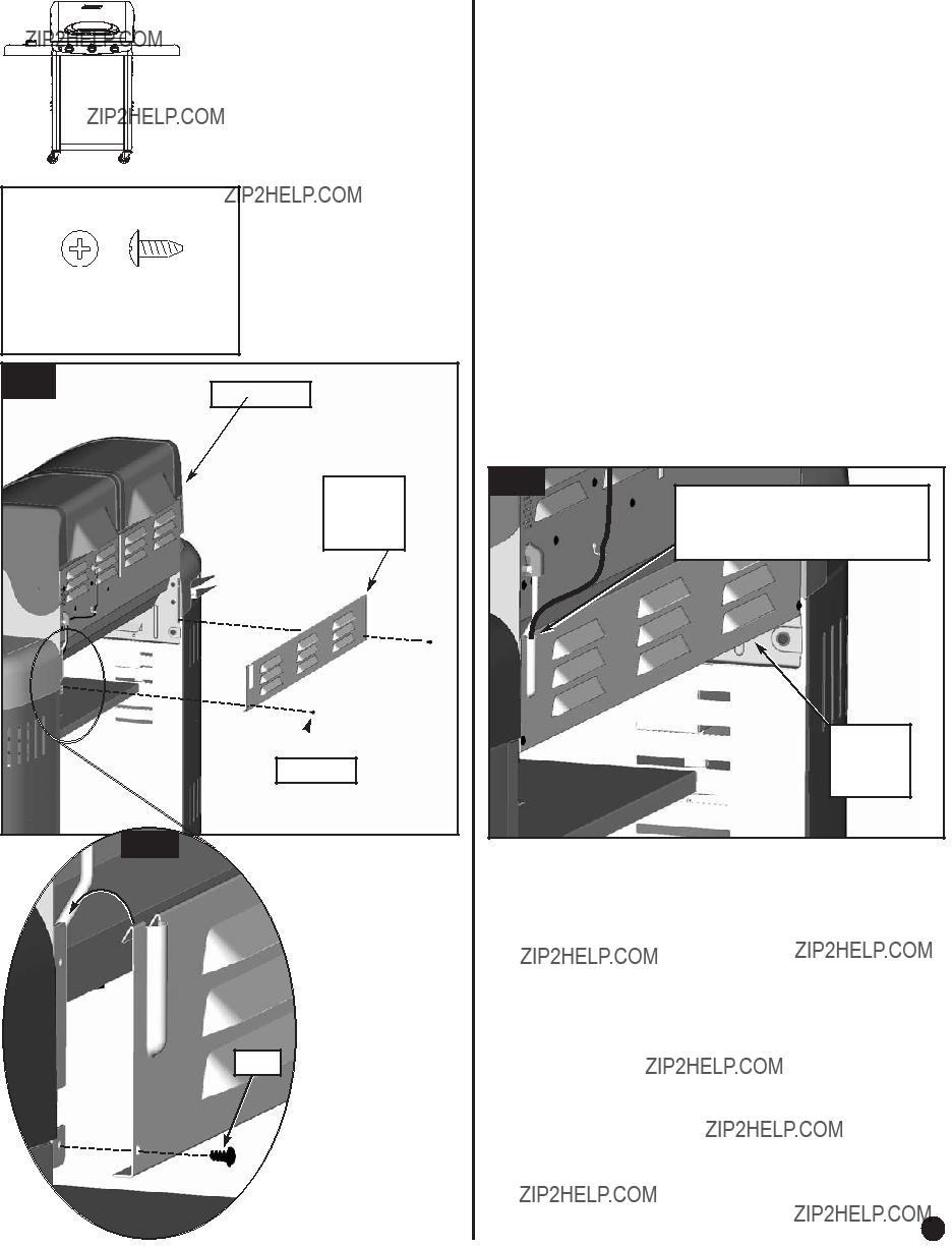
???Be sure to tighten all hardware (screws, nuts, bolts, etc.) at least once a year or each grilling season.
Condition The Grill
???Before using the grill for the first time or after storage,
operate grill 15 minutes on high setting, with lid closed, to burn away oil.
???Once the oil has burned away, check the burner flame per next step.
The Burner Flame
???Keep the grill lid closed and the cooking surfaces in place.
???Observe the burner???s flame from below the grill bottom.
???Flames should appear similar to the good flame shown in Fig. 21 and as follows:
???A good flame should be blue with yellow tip.
???Some yellow tips on flames up to 1" in length are accept- able as long as no carbon or soot deposits appear.
???If flames are excessively yellow and irregular, the oil residue may not be completely burned off, or the venturi may be clogged or may not be properly positioned over the orifices. Allow grill to cool before repositioning venturi over valve and orifices.
???Grills that have been in use for a while sometimes begin to show more yellow flame. A build-up of food deposits, fats or cooking seasonings can cause yellowing flames.
Clean the burner to remove residue and check for clogged burner holes or blocked venturi (see ???Cleaning the Venturi??? pg. 36).
???Regular use of your grill will actually help keep it operating more smoothly.
???Each grill may heat differently. Some units will heat some-
what more to the center and back of grill. Flavor of grilled
food will improve the more you use the grill and as you become familiar with it.
 Holes in Burner
Grilling Tips and Hints
Burner Control Setting Tips
???The high flame setting is too hot for direct cooking. The high flame setting is good for quick searing of meat, then finish cooking on medium or low flame settings.
???Use high flame setting with lid closed to preheat the grill for 5 minutes before cooking and with lid closed for a maximum of 5 minutes after cooking to burn off grease drippings.
???Use medium flame setting for direct cooking of steaks, pork chops, chicken and hamburgers.
???Use low flame setting for roasts and rotisserie foods.
???Thick steaks will finish with a better texture and more juice if first seared on high flame setting then cooked on low flame setting.
Safe Grill Operation
???NEVER leave cooking food unattended. Continually observing the food will help in maintaining an even temperature, conserve fuel, improve the food???s flavor and lessen flare-ups.
???To open grill lid, slowly lift handle to avoid burning in case of a grease fire flare-up.
???DO NOT expose any part of your body directly above the
cooking area.
Food Preparation Hints
Your grill can cook a variety of foods. For best results, follow these instructions:
???Trim excess fat from meat and poultry. Slash any remaining fat to stop curling, but take care not to cut the meat.
???Frozen meat and poultry should be thawed prior to cooking.
???Frozen fish and vegetables will cook without thawing.
???Placing frozen food on very hot porcelain cooking grates can cause temperature shock and crack the finish.
???Salt food after cooking to help prevent drying out the food.
???Brush naturally lean meats with cooking oil or margarine.
???Cook small pieces of tender foods in foil or on special delicate- food cooking grates (see Cooking Methods on pg. 36).
???Apply barbecue, tomato or sugar-based sauces no sooner than the last 10 minutes of cooking.
???Turn food with tongs or spatula; piercing food, especially meat, tends to dry it out.
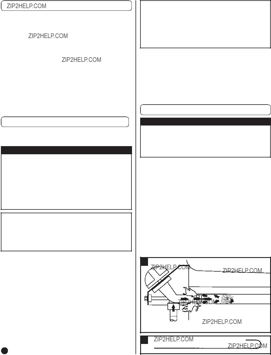
In Case of Grease Fire
Follow These Steps:
1.Shut off gas at the burner valve(s) and stay away!
2.Allow the fire to burn itself out.
3.Once the fire is out and the appliance has cooled, shut off the L.P. cylinder valve.
4.Clean all parts and inspect for damage. Parts to check for damage are the L.P. cylinder, cylinder valve, regulator, gas supply hose, burner valve(s) and burner(s).
5.If any of the above mentioned components are damaged, seek replacement from Coleman before operating the grill again. Locate your nearest service center by calling 1-800-835-3278.
Note:
???Some flare-up adds a smoky flavor and sears food. Excessive grease fires can cause a potentially hazardous situation and damage the grill.
???Avoid excessive flare-ups by preheating the grill with the lid closed for 5 minutes on high setting to burn off grease from previous cooking.
???Cook with lid down and continually monitor cooking food to avoid grease fires and flare-ups.
???Trimming excess fat from meat will reduce grease fires and flare-ups. Cook fatty meat in smaller amounts over indirect heat on low setting.
???Be sure to follow the ???Cleaning and Maintenance Instructions.???
35
 DANGER???, ???
 WARNING???, ???
 CAUTION???.
 DANGER
 WARNING
 CAUTION
 WARNING
 WARNING
 WARNING
 DANGER
 WARNING
 WARNING
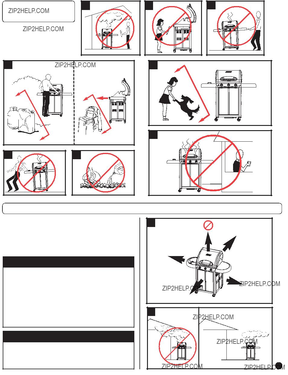
 WARNING
 WARNING
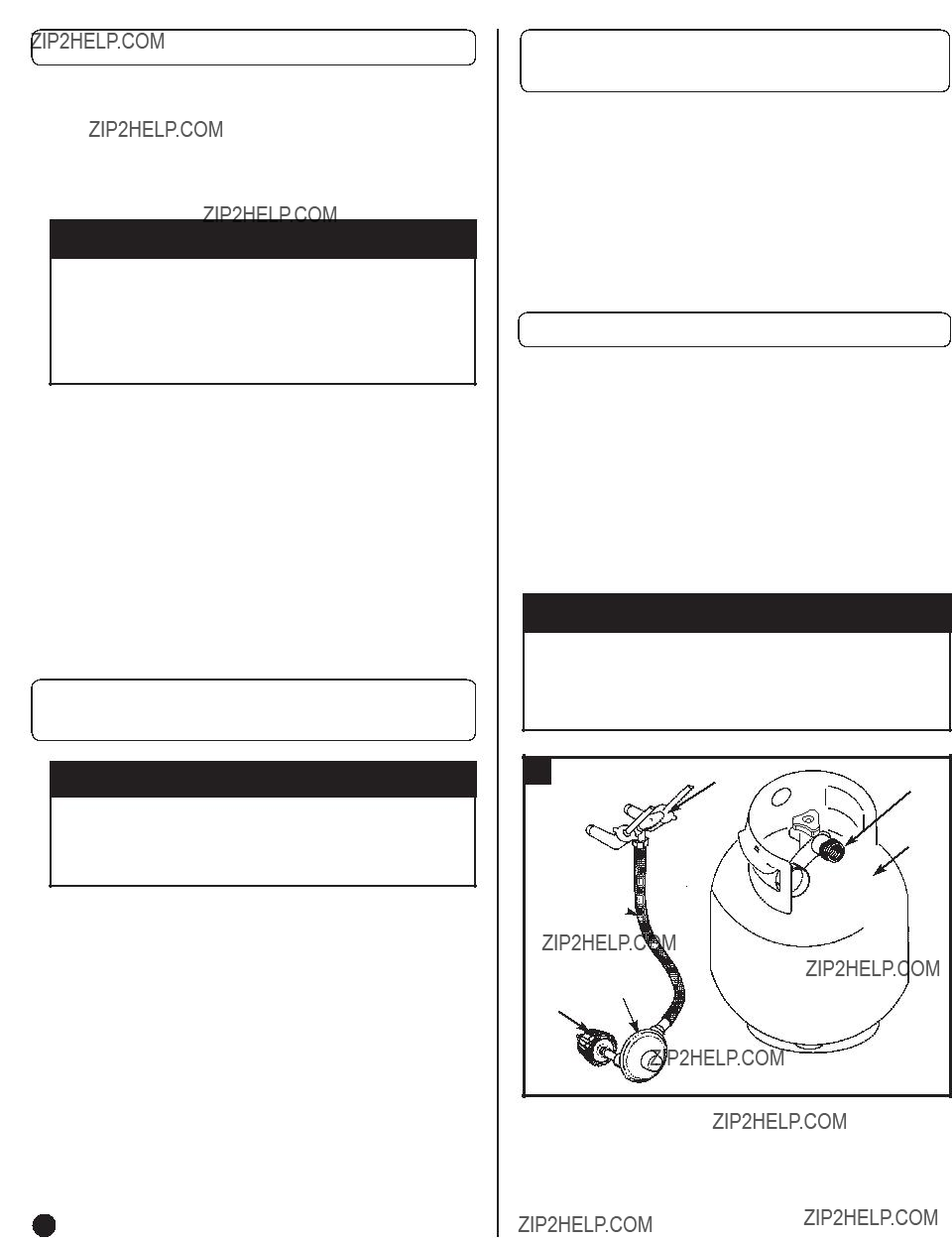
 WARNING
 WARNING
 CAUTION
 G
G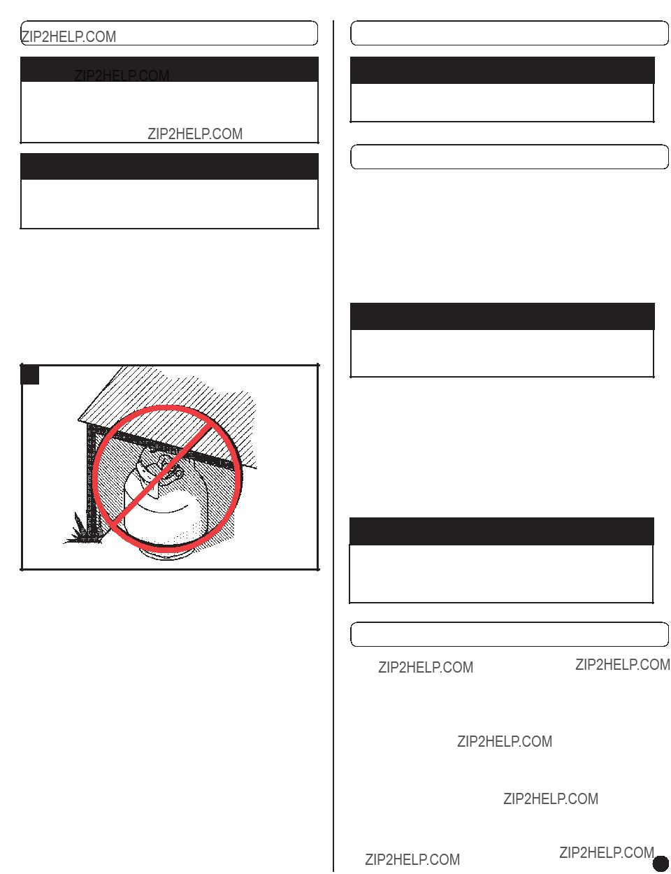
 DANGER
 WARNING
 CAUTION
 WARNING
 WARNING
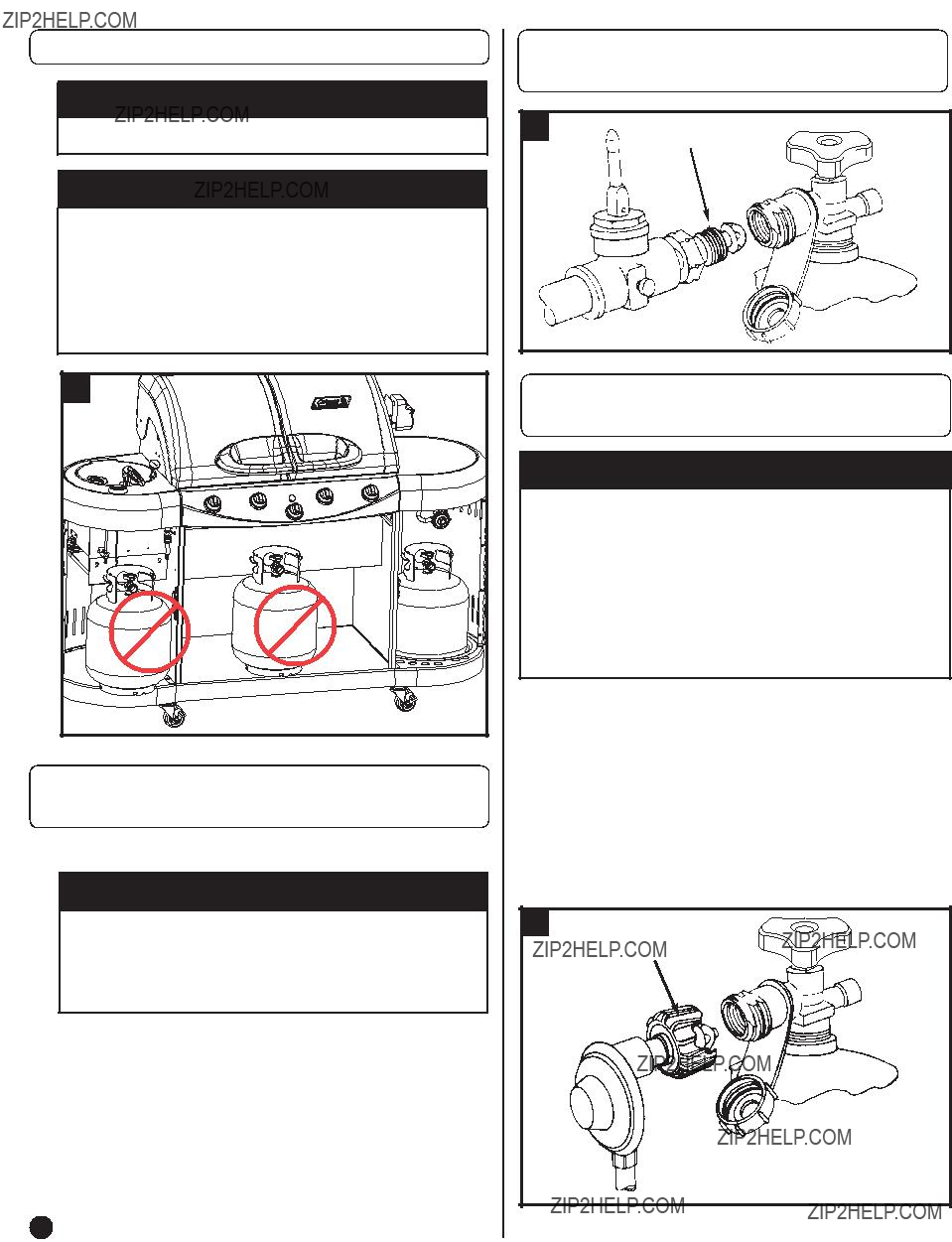
 WARNING
 DANGER
 DANGER
 CAUTION

 Spacers


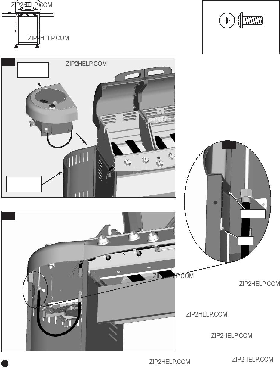

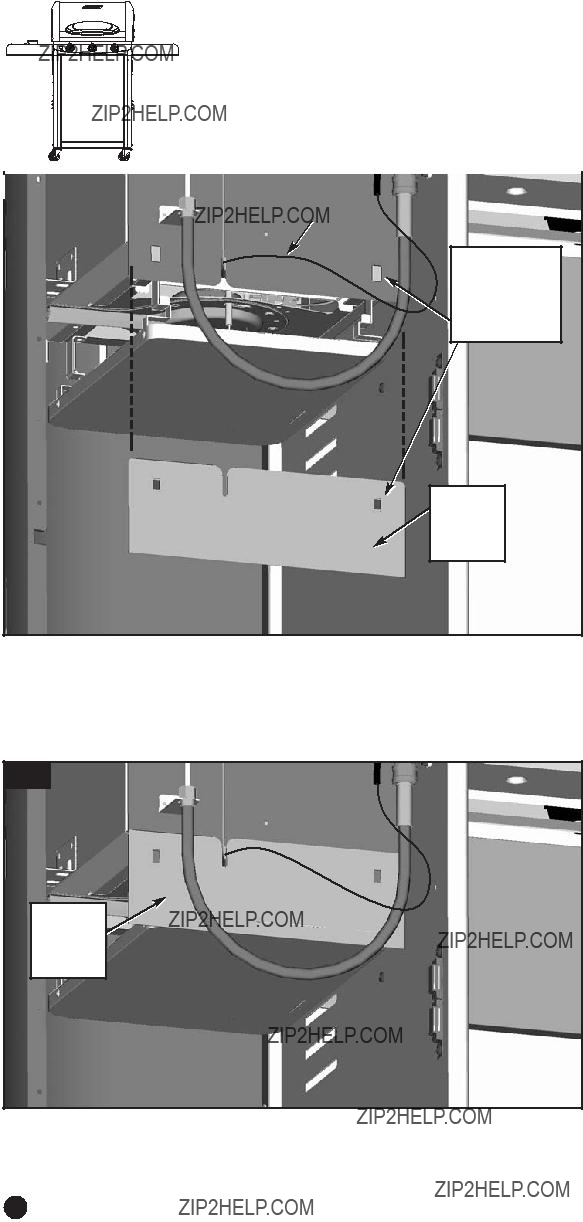

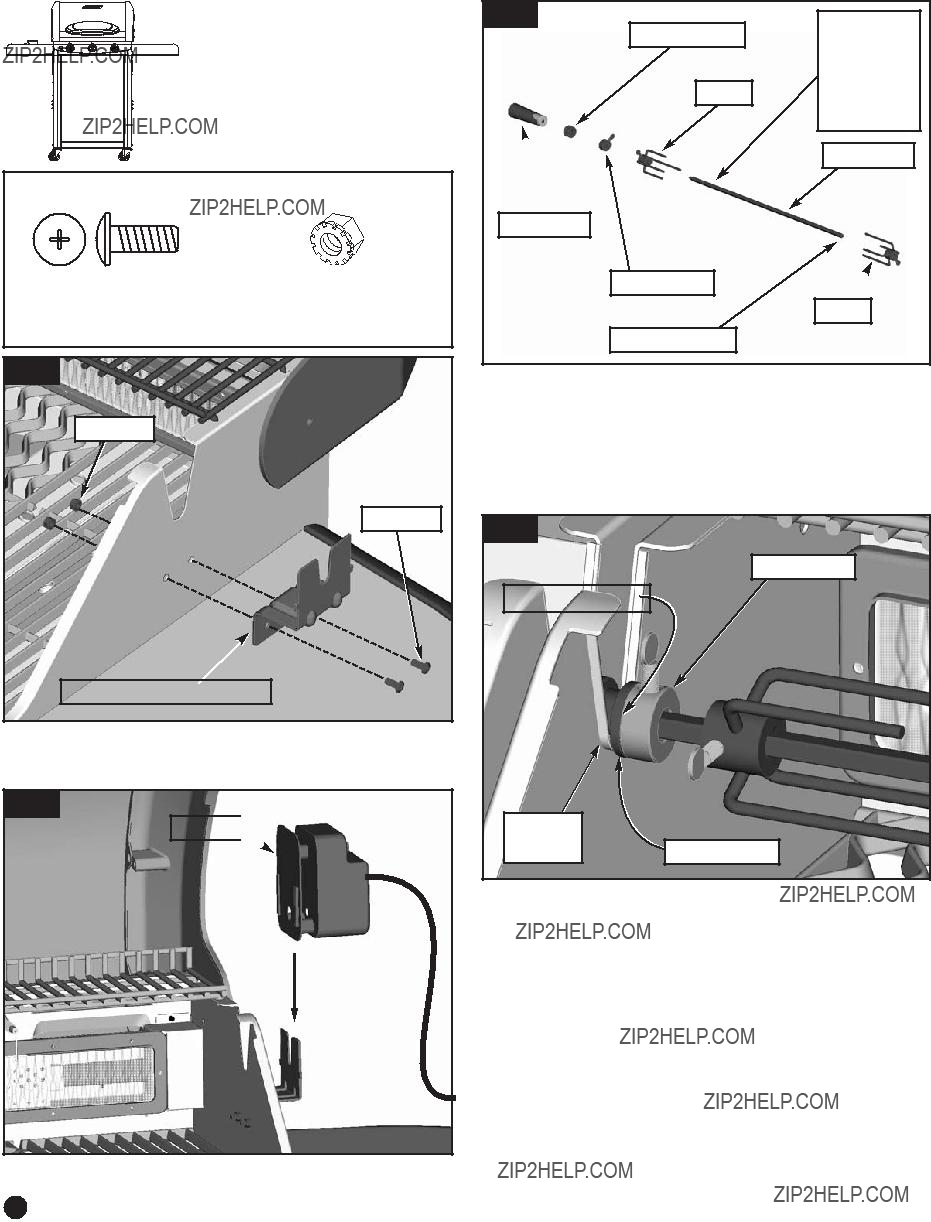
 Back Burner
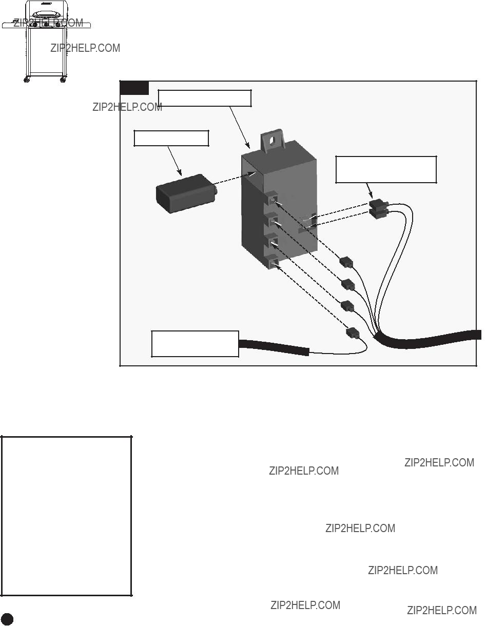

 CAUTION


 WARNING
 CAUTION
 DANGER
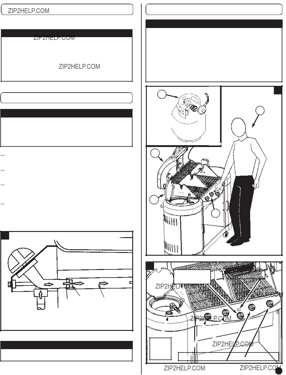
 CAUTION
 WARNING
 1. Regularly check burner venturi tubes for blockage from an insect nest. Read ???Cleaning the Venturi??? on pg. 36 and ???Troubleshooting??? on pg. 37.
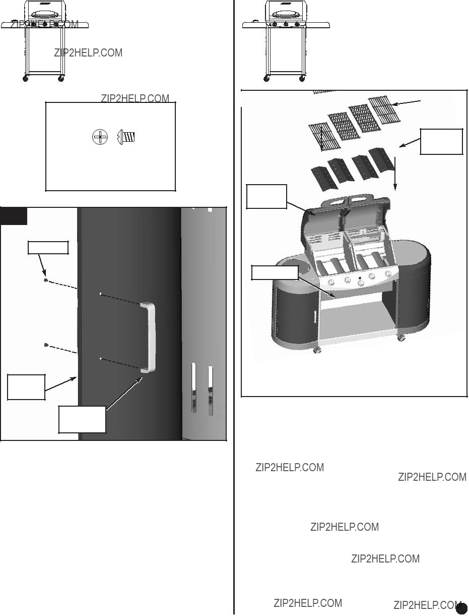
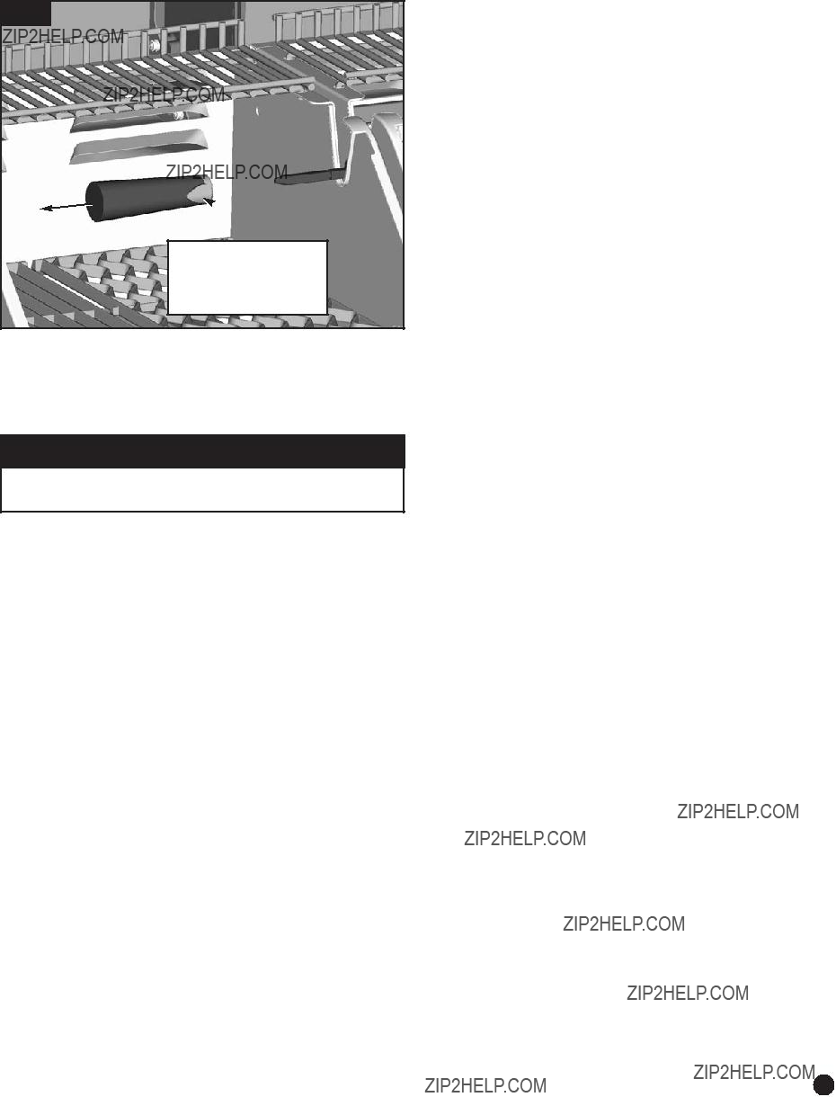
 2. Check that all burner venturi [H] are set over the valve outlets [J] correctly. The valve orifice [K] must be inside the venturi. (Fig. 17)
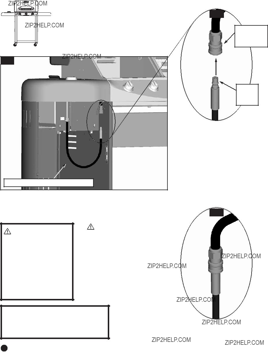
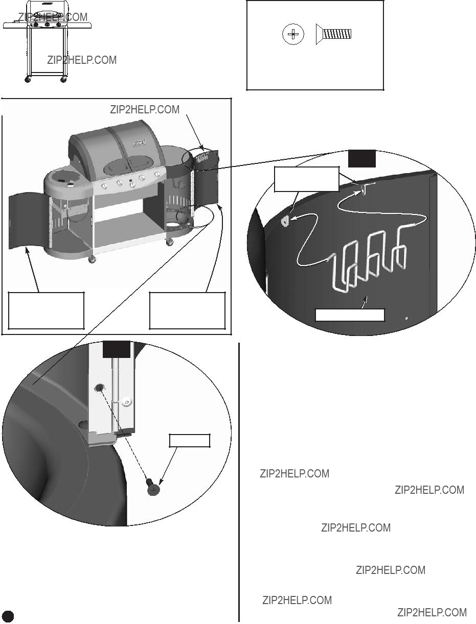
 3. Inspect the gas supply hoses before each use. Hoses can be burned or chafed if they are routed improperly. See that hoses have no kinks, sharp bends or tension. Insure that hoses are at least 3 inches away from any hot surface.
 4. Use only the gas specified.
 5. Keep the grill on a level surface.
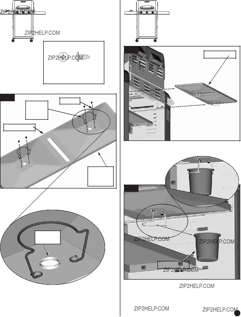
 6. Keep grease pan empty at start up.
 CAUTION
 WARNING
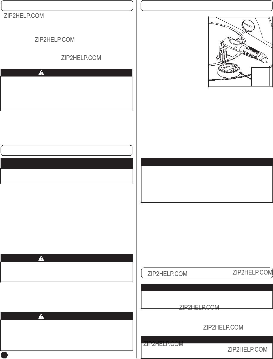
 CAUTION
 CAUTION
 CAUTION
 CAUTION
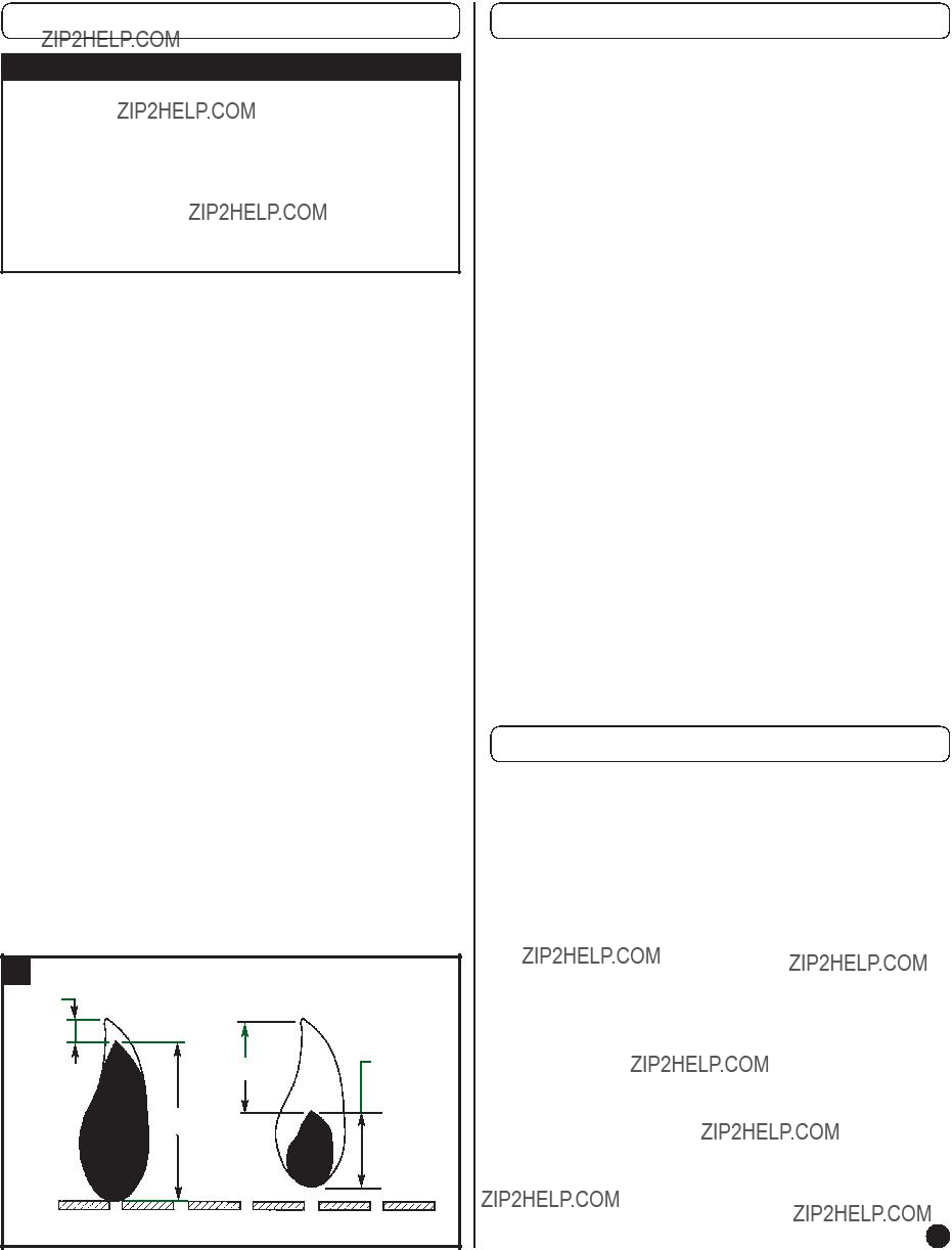
 WARNING
 WARNING
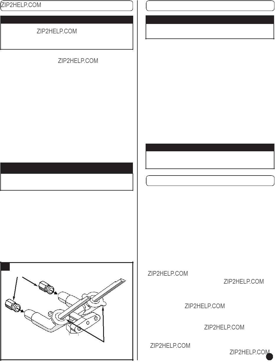
 CAUTION
 DANGER
 CAUTION
 WARNING
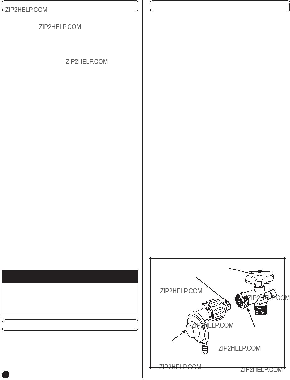
 DANGER

 Yes, Please contact me. 2.
 No, Thanks
 Received as a gift
 First of this type of product owned
 Addition to Coleman products
 Replaced old Coleman product
 Replaced another brand product
 Purchase in addition to another brand