OPERATIONAL
INSTALLATION
MANUAL
OPERATIONAL
INSTALLATION
MANUAL

APX200.2M Power System Amplifier
INTRODUCTION
The Clarion APX200.2M is a
???Full frequency response with low distortion and exceptional signal to noise performance
???Advanced circuit design that features bridgeable and mixed mode operation for use in various systems, including those with satellite speakers and/or subwoofers
???Variable
???Variable bass boost circuit to reinforce low frequency signals that may be lost due to subwoofer box design
???Adjustable input level controls with ground loop isolation accepting a wide range of input signals
???Remote
???
???
???
???Aluminum heat sink for efficient heat dissipation
???Low profile, compact size for space limited installations
ABOUT THE MANUAL AND WARRANTY
To start enjoying your new Clarion
Please fill out and send in the enclosed warranty card to protect your purchase and aid in warranty service. Also, save your original sales receipt as proof of purchase.

OWNER???S MANUAL
DESCRIPTION
The Clarion APX200.2M
The APX200.2M uses an unregulated MOSFET power supply for superior control of output wattage. A
All connections and controls of the APX200.2M are on the end panels and are easy to understand. We use
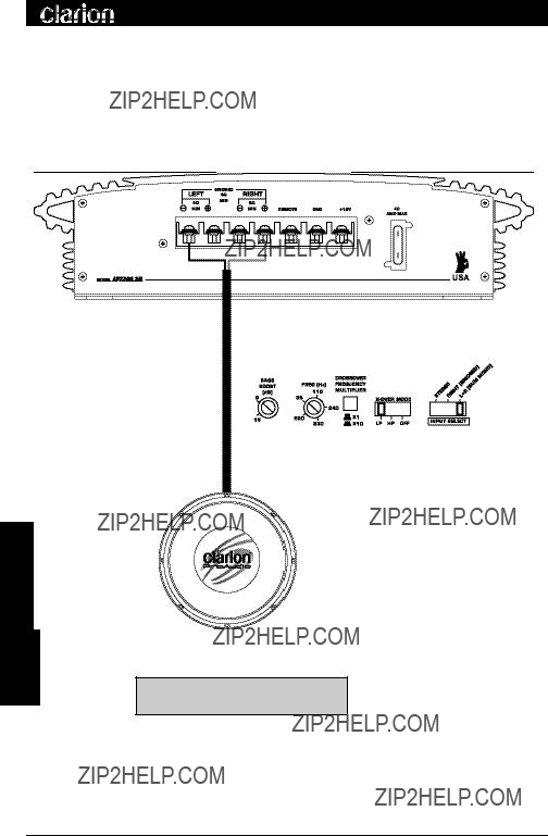
INPUT CONNECTIONS AND AUDIO CONTROLS
The front panel of the APX200.2M contains connections for RCA Inputs, Speaker Level Inputs and Audio Controls as shown below.
The RCA Input Connections are
Figure 1
1

APX200.2M Power System Amplifier
??? Gain Control - This allows you to set the nominal operating level of the amplifier. The amplifier's range, 250mV to 2.5V for RCA inputs or 500mV to 5V for speaker level inputs, can accommodate input levels from virtually any brand of source unit.
??? Bass Boost Control- The amplifier also features a
??? Frequency (Hz) Selection Control - The crossover frequency is fully adjustable between 55Hz and 5500Hz (via the Crossover Frequency Multiplier) for a wide range of crossover points. Use this feature, along with your speaker manufacturer's recommended crossover frequencies, to quickly design a more advanced system (see Applications on page 5.) NOTE: If the
??? Crossover Frequency Multiplier Switch - When engaged, this switch increases the crossover frequency by a factor of 10. Example: If the Freq (Hz) dial is set for 240 Hz, pushing in the Multiplier Switch changes the setting to 2400 Hz.
???
??? Input Mode Switch - This switch allows you to set the input mode. Stereo input allows full left and right stereo operation. Right (bridged) input allows
single channel input for bridged operation. This is especially useful in
(sum mono) allows a stereo input to be summed into a mono output.
??? Speaker Level Inputs - These provide connections for a
WARNING: When using the speaker
2

OWNER???S MANUAL
CONNECTIONS FOR POWER AND SPEAKERS
The rear panel of the APX200.2M contains power and speaker connections as shown below.
Figure 2
3
APX200.2M Power System Amplifier
APPLICATIONS
The Clarion APX200.2M
Bridged - Mono Subwoofer System
Subwoofer 4 Ohms
Set
FREQ to speaker specifications.
Figure 3 - In this application the amplifier is bridged for mono operation to drive a subwoofer.
4

OWNER???S MANUAL
(Set INPUT SELECT Switch to STEREO)
Set
shown.
Set
Set
Figure 4 - In this application, the amplifier is used in stereo and drives two
5

APX200.2M Power System Amplifier
(Set INPUT SELECT Switch to STEREO)
Subwoofer 4 Ohms
NOTE: Chart values based on 4 Ohm speakers.
Figure 5 - The amplifier can be configured for a
6

OWNER???S MANUAL
INSTALLATION
This section lists Mounting and Wiring Precautions for installing a Clarion APX200.2M marine amplifier. Combined with the experience of a professional installer, these safeguards provide enough detail to successfully complete an installation. If you do not have the necessary skills, do not install the amplifier yourself. Instead, see your authorized Clarion dealer for installation recommendations.
MOUNTING PRECAUTIONS
Although the Clarion APX200.2M incorporates heat sinks and protection circuits, mounting the amplifier in a tight space without any air movement can still damage internal circuitry over time. Choose a site that provides adequate ventilation and is isolated from the marine environment. For easy system
In addition, observe the following precautions:
1. For the most efficient cooling, mount the amplifier so cool air runs along the length of the fins rather than across them. Remember, any moving air will dissipate heat.
2.Mount the amplifier on a rigid surface. Avoid mounting to subwoofer enclosures or areas prone to vibration.
3.Prior to drilling, make sure proposed mounting holes will not cut into the fuel tank, fuel lines, or electrical wiring.
WIRING PRECAUTIONS
Read all wiring precautions. If you are not sure of the connections, contact your authorized Clarion dealer.
1.Before installation, make sure the source unit Power switch is in the OFF position.
2.Disconnect the negative
3.When making connections, be sure that each connection is clean and secure. Insulate final connections with electrical tape or shrink tubing. Failure to do so may damage your equipment.
4.A secure clean ground connection is critical to the performance of your Clarion amplifier. Use the shortest ground wire possible and securely connect
to the vessel battery to minimize resistance and avoid noise problems.
7

APX200.2M Power System Amplifier
5. Add an external fuse on the amplifier's positive (+) power lead and connect it as close as possible to the vessel's (+) battery terminal. Use a rating that equals the total current consumption at full output of all amplifiers in the system. Adding an external fuse will protect the electrical system from short circuits that can cause a fire.
6. Refer to Figure 6 when making electrical connections. Connect the amplifier's positive (+) lead via a fuse directly to the positive (+) terminal on
the battery. Do not connect this wire to the vessel's fuse panel. Use
and the
7. When replacing the amplifier 's fuse, always use one having the same current rating. Substituting a
serious damage to the amplifier.
8. Make sure that your vessel's electrical system (alternator, battery, etc.) is capable of handling the additional load. If you are planning a
9. To avoid noise problems, run the amplifier's positive (+) power lead along one side of the vessel to the battery. Run the remote
10. When creating passage holes for the power wire, use grommets to eliminate any sharp edges created during drilling. This will protect the wire from being nicked and causing a short circuit.
11. Extra cable can cause signal loss and act as an "antenna" for noise. Use only
8
OWNER???S MANUAL
Figure 6 - Electrical connections for the APX200.2M
9

APX200.2M Power System Amplifier
SETTING THE GAIN
After completing the installation, follow these steps to set the Gain Control and then perform the Final System Checks.
1.Turn the Gain Control all the way
2.Turn the vessel's Ignition Switch to the ON position. Then turn the ON/OFF Switch on the source units to the ON position. Set all Tone or Equalization
Controls to "flat" positions and turn Loudness off.
3.Play a CD or Tape and set the Volume Control at 75% of full level. NOTE: If the system uses an equalizer, set its frequency controls to "flat" positions.
4.Slowly increase the Gain Control. Stop when you hear a slight distortion of audio.
SETTING THE CROSSOVER
The Clarion APX200.2M features a fully adjustable crossover. To set the crossover, follow these steps.
1.Using the
2.Using the Freq (Hz) Control, select the desired frequency. If the desired frequency exceeds the range of the Freq (Hz) Control, press the Crossover Frequency Multiplier Switch to increase the value by a multiplier of 10.
??? For example, 55Hz x 10 = 550Hz or 550Hz x 10 = 5.5kHz.
SETTING THE BASS BOOST
1.Initially set the Bass Boost control to its full left position (i.e. 0dB).
2.Listen to a variety of music styles (e.g. Rock, Rap, etc.) and slowly increase the Bass Boost control until a noticeable increase in low bass response is perceived.
3.Slowly adjust the Bass Boost control (up or down) to realize the best bass response.
CAUTION: If you hear a "pop" (due to speaker
10

OWNER???S MANUAL
FINAL SYSTEM CHECKS
1. Start the engine and turn on the source unit. After a
of the system's power, use care when adjusting controls.
2. Turn the Balance Controls to their extreme positions and listen to the results. Audio imaging should match control settings (audio from the left speaker when balance is left).
3. Increase the volume and verify that the amplifier reproduces audio (at full frequencies) without distortion. If you hear distortion, check the connections and verify that the Gain Control is set correctly. Another possibility is damaged speakers or
TROUBLESHOOTING
Problem
No Audio.
Solution
Low or no remote
Blown amplifier fuse. Replace with new
Power wires not connected. Check battery and ground wiring at amplifier; also check battery connections.
Speaker leads shorted. Check speaker continuity to ground, it should not show a common ground.
Speakers not connected or are blown. Check speaker connections at amplifier, measure coil impedance.
Problem
Audio cycles on and off.
Solution
Thermal protection circuits are shutting amplifier off. Check location for adequate ventilation; consult an authorized Clarion Audio Dealer.
11

APX200.2M Power System Amplifier
Problem
Distorted audio.
Solution
Gain is not set properly, or damaged speaker cones. Review Setting Gain; inspect each speaker cone for signs of damage (i.e. frozen cone, burning smell, etc.)
Problem
Audio lacks punch.
Solution
Speakers wired incorrectly, which causes cancellation of bass frequencies. Check polarity of wires from amplifier to each speaker as defined by the system design.
Problem
Amplifier fuse keeps blowing.
Solution
Incorrect wiring or short circuit. Review Installation and check all wiring connections.
Problem
Whining or ticking noise in the audio with engine on.
Solution
Amplifier is picking up alternator noise or radiated noise. Turn down input gain; move audio cables away from power wires. Check power and ground connections on amplifier; install an
PRODUCT SPECS
12

OWNER???S MANUAL
NOTES
13

661 W. Redondo Beach Blvd.
Gardena, CA 90247