English connectionmanual Installationand Wire
3. GENERAL CAUTIONS
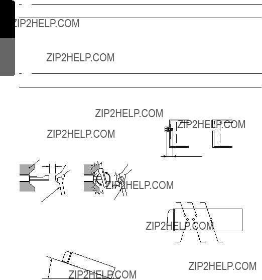
4. CAUTIONS ON INSTALLATION
1.Prepare all articles necessary for installing the main unit before starting.
2.This model is used with the LCD panel slid forwards (shell loading system). On some types of cars, the LCD panel may touch the dashboard or shift lever, in which case it can- not be installed. Check that the set will not hamper operation of the shift lever before choosing the place of installation.(Figure 2)
Dashboard
Figure 2
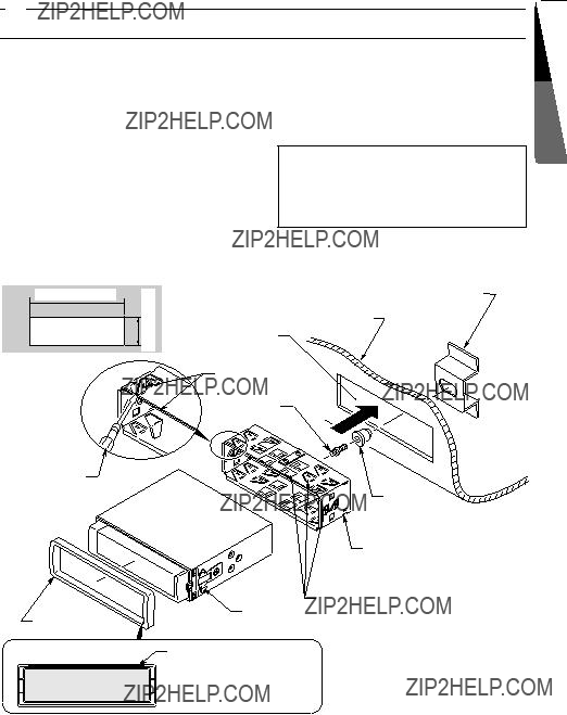
5.Use the enclosed screws for installation. Us- ing other screws can cause damage. (Figure
4)


 Damage
Max. 8 mm
Figure 4
6.The source unit has mounting screw holes for NISSAN (N marks) and TOYOTA (T marks) vehicles.
T N T
3.Install the unit within 30?? of the horizontal plane. (Figure 3)
Max. 30??
Figure 3
4.If you have to do any work on the car body, such as drilling holes, consult your car dealer beforehand.
??? Fixed Mount (TOYOTA, NISSAN and other ISO/DIN equipped vehicles)
English connectionmanual Installationand Wire
This unit is designed for fixed installation in the dashboard.
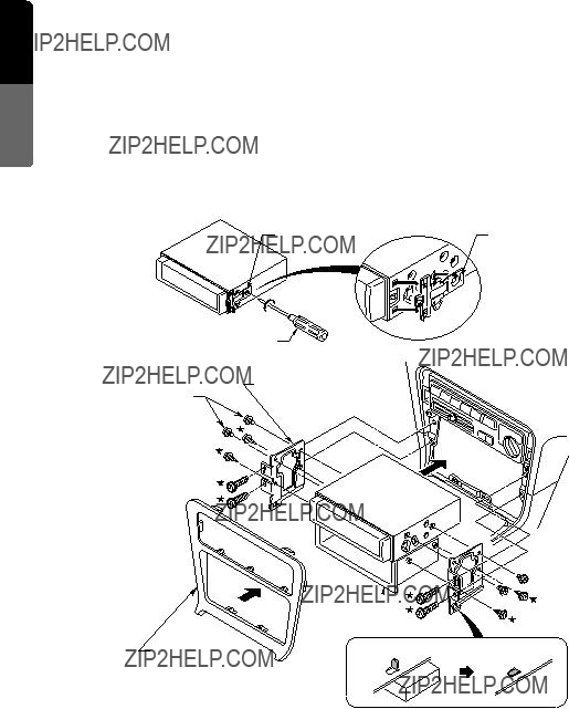
If the vehicle is equipped with a factory-installed radio, install the main unit with the parts and screws marked (??? ). (Figure 8)
If the vehicle is not equipped with a factory-in- stalled radio, obtain an installation kit to install the main unit in the following procedure.
1.Remove the screws from both side of the main unit. Then, at either side, lift the leaf spring until the engaging claws are released from the holes, and slide the spring to the di-
rection of arrow to remove it. Repeat the same for the other side to remove the springs from the both sides. (Figure 7)
2.Secure the mounting brackets to the chassis as shown in Figure 8. Holes are pre-tapped for TOYOTA and NISSAN vehicles; modification, such as drilling new holes, of the mounting brackets may be required for other models.
3.Wire as shown in Section 8.
4.Secure the unit in the dashboard, and then reassemble the dashboard and the centre panel.
Main Unit
2-Spring 
Main Unit
Centre Panel (Note 1)
???: The screws with this mark are enclosed in this set.
???: The parts and screws with this mark are used to install radio or included in
Pocket 
Note 2 
Note 1: In some cases, the centre panel may re- quire some modification (trimming, filling, etc.).
Note 2: If a hook on the installation bracket inter- feres with the unit, bend and flatten it with a nipper or a similar tool.
Purple/Black
2
Purple
1
 *
* 
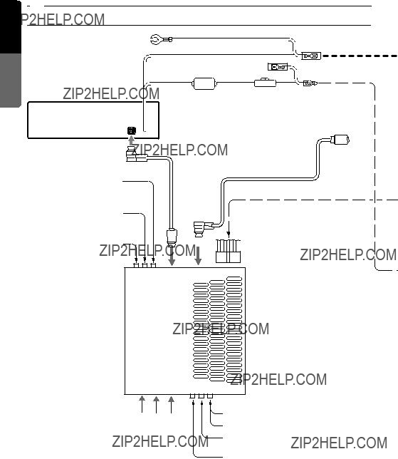
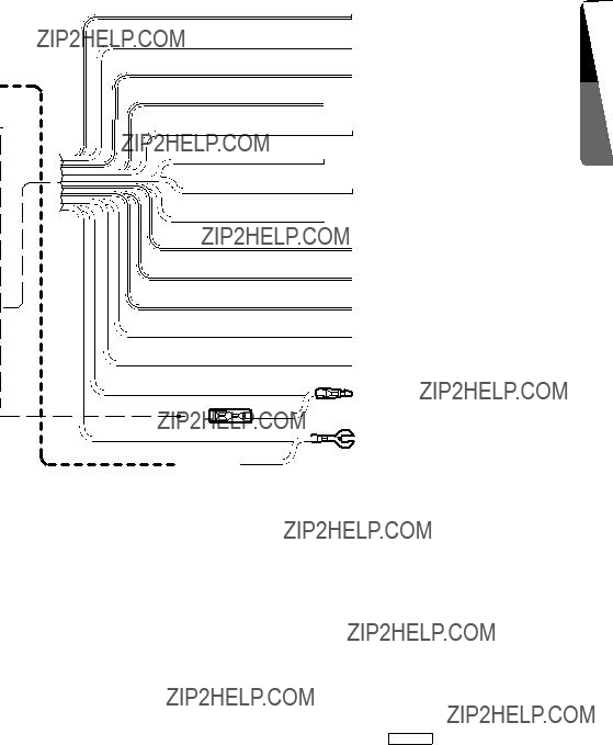
English connectionmanual Installationand Wire
??? 1: Connecting the PHONE MUTE Terminal
The lead included with the unit must be connected to the specified position of the vehicle???s con- nector in order to use the ???triggered audio mute for cellular telephones??? function.
???2: Use the attached extension lead when necessary. (Provided with this unit)
Note : Before making any installation, disconnect the car battery - (negative) cable.
???3: When a DSP (sold separately) is connected and the internal amp of the Tuner Amp Unit is used, set the normal DSP select switch to ???D???. Then, the AUDIO OUT (IN) terminal of the Tuner Amp
???4: Connect to a separately sold amp, DSP, etc. with a separately sold RCA cord (L,R).
???5: Connect to a separately sold Rear view monitor.
???6: Connect to separately sold VTR equipment.
???7: DVD DECK and DVD changer can not be connected at the same time.
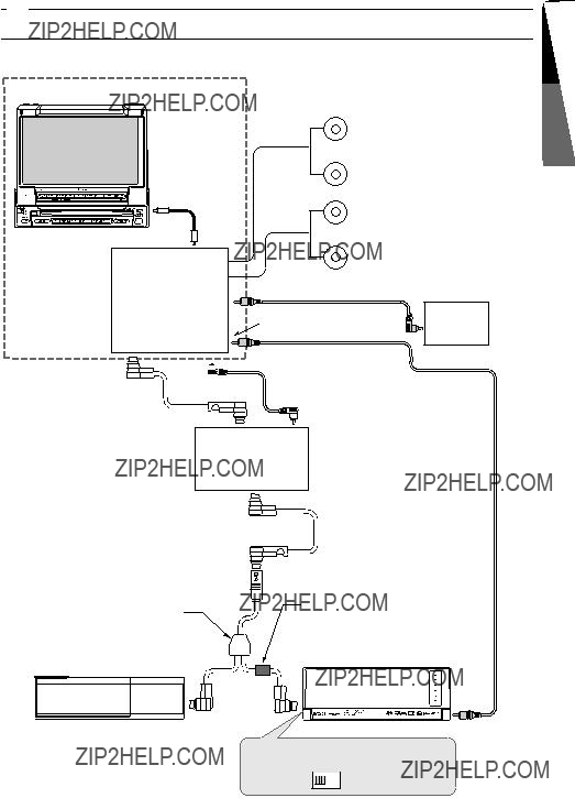
9. SAMPLE SYSTEMS
??? Sample System 1
VRX835
Front
Speakers
Rear
Speakers
English connectionmanual Installationand Wire
RCA video cable (sold separately)
Tuner Amp Unit
Rear View
DVD input
Monitor
 TV Tuner input
TV tuner
(TTX7501z)
CeNET Cable
(included the Changer)
VCZ625) the (included cable video RCA
(CCA-519-500,(Included the DVD changer) sold separately)
DVD Changer
(DCZ625)
Set the [CENET/STAND ALONE]
switch to the [CeNET] position.
CeNET  STAND
STAND
ALONE
VRX835 55
RCA video cable
(sold separately)Rear View
Monitor
AV Adapter cable (CCA-389,
sold separately)
VTR
CeNET
TV Tuner
(TTX7501z)
CeNET cable (included the DPH910) 
Digital Sound
Processor
(DPH910)
4-Channel Amplifier
2-Channel Amplifier
 RCA cable (sold separately)
Set the [CENET/STAND ALONE] switch to the [CeNET] position.
CeNET  STAND
STAND
ALONE


 CAUTION