VRX630

Installation and Wire connection manual

1. BEFORE STARTING

1. This set is exclusively for use in cars with a negative ground 12 V power supply.

2. Read these instructions carefully.

3. Be sure to disconnect the battery ??? ??? termi- nal before starting. This is to prevent short circuits during installation. (Figure 1)

Wire and Installation

manual connection English

2. PACKAGE CONTENTS

VRX630 43

3. GENERAL CAUTIONS

English

1.Do not open the case.There are no user ser- viceable parts inside. If you drop anything into the unit during installation, consult your dealer or an authorized CLARION service centre.

2.Use a soft, dry cloth to clean the case. Never use a rough cloth, thinner, benzine, or alco- hol, etc. For tough dirt, apply a little cold or warm water to a soft cloth and wipe off the dirt gently.

Installation connection

4. CAUTIONS ON INSTALLATION

Wire and manual

1.Prepare all articles necessary for installing the main unit before starting.

2.This model is used with the LCD panel slid forwards (shell loading system). On some types of cars, the LCD panel may touch the dashboard or shift lever, in which case it can- not be installed. Check that the set will not hamper operation of the shift lever before choosing the place of installation.(Figure 2)

3.Install the unit within 30?? of the horizontal plane. (Figure 3)

5.Use the enclosed screws for installation. Us- ing other screws can cause damage.

(Figure 4)

6.The source unit has mounting screw holes for NISSAN (N marks) and TOYOTA (T marks) vehicles.

T N T

NT N

4.If you have to do any work on the car body, such as drilling holes, consult your car dealer beforehand.

44 VRX630

5. INSTALLING THE MAIN UNIT

??? Universal Mount

1.Place the universal mounting bracket into the instrument panel, use a screwdriver to bend each stopper of the universal mounting bracket inward, then secure the stopper as shown in Figure 6.

2.Wire as shown in Section 8.

3.Insert the main unit into the universal mount- ing bracket until it locks.

4.Mount the outer escutcheon so that all the hooks are locked.

??? Console opening dimensions

Notes:

1)Some car models require special mounting kits for proper installation. Consult your Clarion dealer for details.

2)Fasten the front stopper securely to prevent the main unit from coming loose.

Wire and Installation

manual connection English

Stoppers

Special Screw

Screwdriver

Rubber cap

Main unit

Universal mounting bracket

Stoppers

2-Spring

Outer escutcheon

Note: Set the outer escutch- eon so that its metallic part on the back side fits the upper edge of the main unit.

VRX630 45

??? Fixed Mount (TOYOTA, NISSAN and other ISO/DIN equipped vehicles)

Wire and Installation English manual connection

This unit is designed for fixed installation in the dashboard.

If the vehicle is equipped with a factory-installed radio, install the main unit with the parts and screws marked (??? ). (Figure 8)

If the vehicle is not equipped with a factory-in- stalled radio, obtain an installation kit to install the main unit in the following procedure.

1.Remove the screws from both side of the main unit. Then, at either side, lift the leaf spring until the engaging claws are released from the holes, and slide the spring to the direction of arrow to remove it. Repeat the

same for the other side to remove the springs from the both sides. (Figure 7)

2.Secure the mounting brackets to the chassis as shown in Figure 8. Holes are pre-tapped for TOYOTA and NISSAN vehicles; modifica- tion, such as drilling new holes, of the mount- ing brackets may be required for other mod- els.

3.Wire as shown in Section 8.

4.Secure the unit in the dashboard, and then reassemble the dashboard and the centre panel.

The screws with this mark are enclosed in this set.

The parts and screws with this mark are used to install radio or included in the installation kit.

Note 1: In some cases, the centre panel may re- quire some modification (trimming, filling, etc.).

Note 2: If a hook on the installation bracket inter- feres with the unit, bend and flatten it with a nipper or a similar tool.

46 VRX630

6. REMOVING THE MAIN UNIT

1.When the rear of the main unit has been se- cured with the method shown in Figure 6 unfasten the special screw.

2.Remove the outer escutcheon.

3.Insert the hook plate between the spring and the universal mounting bracket, fit tab B of

the spring into hole A of the hook plate, then pull the main unit out by the hook plate. (In- sert both the right and left edges of the hook plate.) (Figure 9)

Note: Keep the hook plate. You cannot remove the main unit without disengaging the hook plate.

Wire and Installation

manual connection English

7. CAUTIONS ON WIRING

1.Be sure to turn the power off before wiring.

2.Be particularly careful where you route the wires.

Keep them well away from the engine, and exhaust pipe, etc. Heat may damage the wires.

3.If the fuse should blow, check to see if the wiring is correct.

If it is, replace the fuse with a new one with the same amperage rating as the original.

4.When any fuse is to be replaced, pull out the fuse (15A) at the rear of the main unit and put in a new one (Fig.10).

CAUTION

After the connection, fix the lead by a clamp or insulation tape for protection.

5.When connecting the ground lead, fasten the ground lead (black) securely to a clean metal plate on the car. (Figure 11)

If the set is insufficiently grounded, it may not operate or there may be noise.

Figure 11

Figure 10

VRX630 47

Wire and Installation English manual connection

8. WIRE CONNECTION

VISUAL/CCD/DVD changer terminal

AUDIO 4CH. OUTPUT terminal

Gray Red

Front right

Gray White

Front left

Brack Red

Rear right

White

Brack

Rear left

???1:Connect securely to the metal part of the vehicle with a screw, etc.

???2:Connect to the power supply terminal which can be turned on and off by the ignition switch.

???3:Connect to the power supply terminal where the power is always supplied regardless of whether the ignition switch is turned on or off.

???4:Connect to the remote turn-on lead of amplifiers.

???5:Use the attached extension lead when necessary.

???6:Connect the terminal to the lead wire on the lamp side of the parking brake lamp switch. After connection, apply the parking brake, then check that the TV displays an image.

??? If the PKB lead is not connected to the side brake, some units may not operate.

48 VRX630

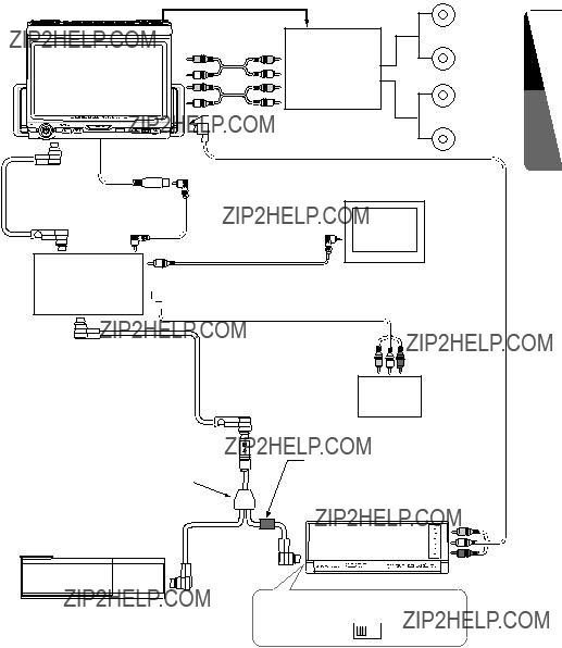
??? Connecting the Accessories

??? Connection to the external amplifier

The external amplifier can be connected to the AUDIO 4CH. OUTPUT terminal (RCA pin jack) on the main unit. In other words, it can be connected provided the DSP is connected.

??? Connection to the CCD camera for vehicle

The CCD CAMERA for vehicle can be connected to the system expansion terminal on the main unit. For detailed information, refer to the instruction sheet or manual for the CCD CAMERA.

Notes:

???A power supply box (sold separately) is required for connection of the main unit and the CCD CAMERA.

???While the CCD CAMERA is used, the navigation cannot be turned on.

???The power supply box for camera CCA-147 can not be used. Please use The CCA-188 instead.

???If the specified lead of the cellular phone is connected to the phone mute lead of the source unit, the audio mute is available when the cellular tele- phone is used.

For audio mute setting in cellular telephone use, see page 32.

??? TV Tunner

When the TV TUNER is to be connected, connect the Ce NET connector and RCA PIN (yellow). For detailed information, refer to the instruction manual of the TV TUNER.

Wire and Installation

manual connection English

??? Connecting the parking brake lead

Connect the lead to parking brake lamp earth in the meter panel.

Parking brake lamp

+ lead to battery

Notes:

- cord parking

Connect these three leads.

brake signal

lead

Parking brake lead (bright green)

Parking brake

VRX630 49

Wire and Installation English manual connection

9. SAMPLE SYSTEMS

??? Sample System 1

Main Unit

(VRX630)

??? To enable the correct input, it is necessary to configure the VRX630 as described on page 30.

CeNET cable (included the TV tuner)

RCA video cable (included the TV tuner)

TV Tuner

(TTX7501z)

CeNET Cable

(included the Changer)

Ferrite clamp

CeNET Y-adapter (CCA-519-601, sold separately)

CD Changer

(CDC655z/655Tz/1255z/

DCZ625)

???When two CD changers or MD changers are connected, CCA-519-601 is required.

(Included the DVD changer)

DVD Changer

(VCZ625)

Set the [CeNET/STAND ALONE]

switch to the [CeNET] position.

CeNET STAND

ALONE

50 VRX630

??? Sample System 2

Wire and Installation

manual connection English

CeNET cable (included the TV tuner)

TV Tuner

RCA video cable (included the TV tuner)

RCA video cable (sold separately)

Rear

Monitor

???Images from the DVD changer cannot be displayed.

(TTX7501z)

AV Adapter cable (CCA-389, sold separately)

CeNET Cable

(included the Changer)

???To enable the correct input, it is necessary to configure the VRX630 as described on page 30.

CeNET Y-adapter (CCA-519-601, sold separately)

CD Changer

(CDC655z/655Tz/1255z/

DCZ625)

???When two CD changers or MD changers are connected, CCA-519-601 is required.

VTR

Ferrite clamp

(Included the DVD changer)

DVD Changer

(VCZ625)

Set the [CeNET/STAND ALONE]

switch to the [CeNET] position.

CeNET STAND

ALONE

VRX630 51

??? Sample System 3

Wire and Installation English manual connection

Main Unit

(VRX630)

VIDEO INPUT terminal

CCD camera

???To enable the correct input, it is necessary to configure the VRX630 as described on page 30.

RCA video cable (included the TV tuner)

TV Tuner

(TTX7501z)

Amp remote

CeNET Cable (included the Changer)

Digital Sound

ProcessorSub-

woofer

(DPH910)

2-channel

RCA PIN cable power amplifier

(sold separately) Digital optical fiber cable(sold separately)

CD Changer

(CDC655z/655Tz/1255z/

DCZ625)

52 VRX630