Se n d d o c u m e n t a t i o n c o m m e n t s t o m d s f e e d b a ck - d o c @ c i s c o . c o m .
C H A P T E R 35
Configuring iSCSI
Cisco MDS 9000 Family IP storage (IPS) services extend the reach of Fibre Channel SANs by using open-standard, IP-based technology. The switch allows IP hosts to access Fibre Channel storage using the iSCSI protocol.
Note The iSCSI feature is specific to the IPS module and is available in Cisco MDS 9200 Switches or Cisco MDS 9500 Directors.
The Cisco MDS 9216I switch and the 14/2 Multiprotocol Services (MPS-14/2) module also allow you to use Fibre Channel, FCIP, and iSCSI features. The MPS-14/2 module is available for use in any switch in the Cisco MDS 9200 Series or Cisco MDS 9500 Series.
For information on configuring Gigabit Ethernet interfaces, see the ???Configuring Gigabit Ethernet Interfaces??? section on page 37-4.
This chapter includes the following sections:
???About iSCSI, page 35-1
???Configuring iSCSI, page 35-3
???iSCSI High Availability, page 35-38
iSCSI Authentication Setup Guidelines and Scenarios, page 35-45 About iSCSI Storage Name Services, page 35-58
About iSNS Client Functionality, page 35-59 Creating an iSNS Client Profile, page 35-59 About iSNS Server Functionality, page 35-62 Configuring iSNS Servers, page 35-63 Default Settings, page 35-72
About iSCSI
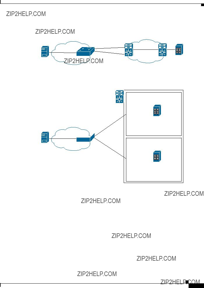
The iSCSI feature consists of routing iSCSI requests and responses between iSCSI hosts in an IP network and Fibre Channel storage devices in the Fibre Channel SAN that are accessible from any Fibre Channel interface of the Cisco MDS 9000 Family switch (see Figure 35-1).
Chapter 35 Configuring iSCSI
About iSCSI
Figure 35-1 Transporting iSCSI Requests and Responses for Transparent iSCSI Routing
Intelligent
(Through the IPS module)
Each iSCSI host that requires access to storage through the IPS module or MPS-14/2 module needs to have a compatible iSCSI driver installed. (The Cisco.com website at http://www.cisco.com/cgi-bin/tablebuild.pl/sn5420-scsi provides a list of compatible drivers). Using the iSCSI protocol, the iSCSI driver allows an iSCSI host to transport SCSI requests and responses over an IP network. From the host operating system perspective, the iSCSI driver appears to be a SCSI transport driver similar to a Fibre Channel driver in the host.
The IPS module or MPS-14/2 module provides transparent SCSI routing. IP hosts using the iSCSI protocol can transparently access targets on the Fibre Channel network. Figure 35-1 provides an example of a typical configuration of iSCSI hosts connected to an IPS module or MPS-14/2 module via the IP network access Fibre Channel storage on the Fibre Channel SAN.
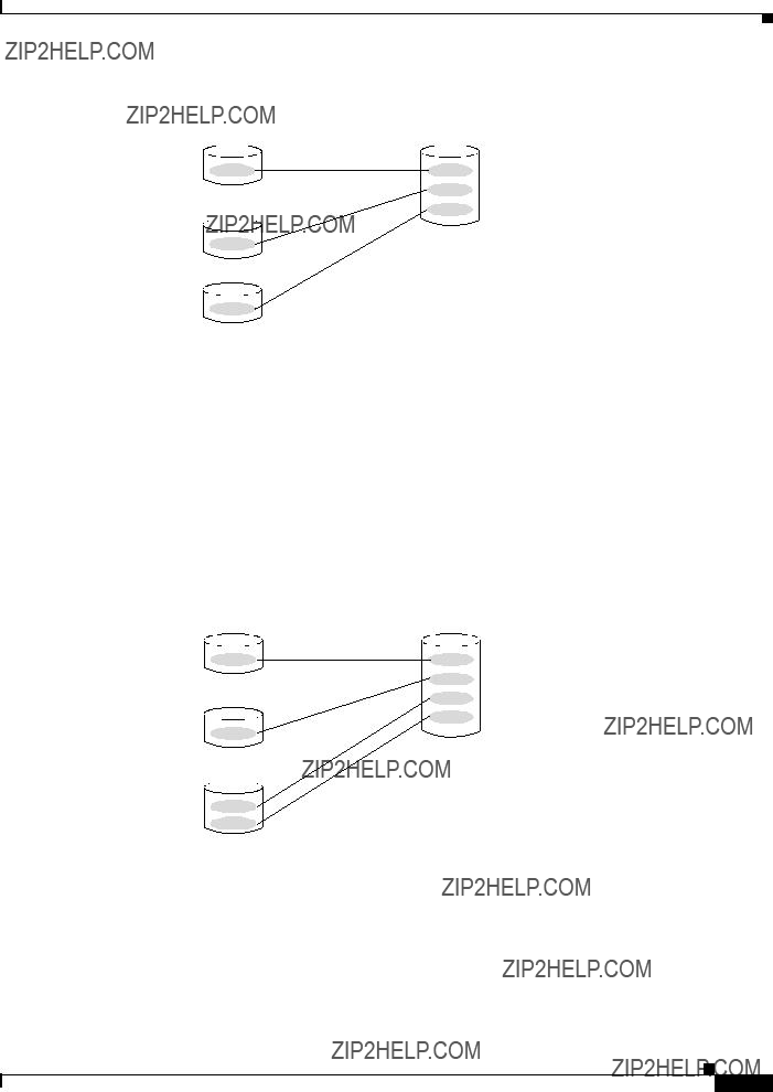
The IPS module or MPS-14/2 module create a separate iSCSI SAN view and Fibre Channel SAN view. For the iSCSI SAN view, the IPS module or MPS-14/2 module create iSCSI virtual targets and then maps them to physical Fibre Channel targets available in the Fibre Channel SAN. They present the Fibre Channel targets to IP hosts as if the physical iSCSI targets were attached to the IP network (see Figure 35-2).
Figure 35-2 iSCSI SAN View???iSCSI virtual targets
Chapter 35 Configuring iSCSI
Configuring iSCSI
Fibre Channel SAN View???iSCSHI Host as an HBA
Figure 35-4 iSCSI to FCP (Fibre Channel) Routing
IP host A
iqn.host A
iSCSI Session
Routing SCSI from the IP host to the Fibre Channel storage device consists of the following main actions:
The iSCSI requests and responses are transported over an IP network between the hosts and the IPS module or MPS-14/2 module.
The SCSI requests and responses are routed between the hosts on an IP network and the Fibre Channel storage device (converting iSCSI to FCP and vice versa). The IPS module or MPS-14/2 module performs this conversion and routing.
The FCP requests or responses are transported between the IPS module or MPS-14/2 module and the Fibre Channel storage devices.
FCP (the Fibre Channel equivalent of iSCSI) carries SCSI commands over a Fibre Channel SAN. Refer to the IETF standards for IP storage at http://www.ietf.org for information on the iSCSI protocol.
Configuring iSCSI
Cisco MDS 9000 Family Configuration Guide
OL-6973-03, Cisco MDS SAN-OS Release 2.x
Chapter 35 Configuring iSCSI
Configuring iSCSI
???
???
???
???Presenting iSCSI Hosts as Virtual Fibre Channel Hosts, page 35-10 iSCSI Access Control, page 35-19
iSCSI Session Authentication, page 35-22
iSCSI Immediate Data and Unsolicited Data Features, page 35-25 iSCSI Interface Advanced Features, page 35-26
Displaying iSCSI Information, page 35-29
Enabling iSCSI
To use the iSCSI feature, you must explicitly enable iSCSI on the required switches in the fabric. By default, this feature is disabled in all switches in the Cisco MDS 9000 Family.
To enable iSCSI on any participating switch, follow these steps:
Step 1
Step 2
Caution When you disable this feature, all related configurations are automatically discarded.
Creating iSCSI Interfaces
Step 1
switch# config terminal
switch(config)# interface gigabitethernet 2/1 switch(config-if)# no shutdown
Step 2
exit
interface iscsi 2/1 no shutdown
Chapter 35 Configuring iSCSI
Configuring iSCSI
Presenting Fibre Channel Targets as iSCSI Targets
???Dynamic mapping???automatically maps all the Fibre Channel target devices/ports as iSCSI devices. Use this mapping to create automatic iSCSI target names.
???Static mapping???Manually create iSCSI target devices and map them to the whole Fibre Channel target port or a subset of Fibre Channel LUNs. With this mapping, you must specify unique iSCSI target names.
Static mapping should be used when iSCSI hosts should be restricted to subsets of LUs in the Fibre Channel targets and/or iSCSI access control is needed (see the ???iSCSI Access Control??? section on page 35-19). Also, static mapping allows configuration of transparent failover if the LUs of the Fibre Channel targets are reachable by redundant Fibre Channel ports (see the ???Transparent Target Failover??? section on page 35-38).
The IPS module or MPS-14/2 module does not import Fibre Channel targets to iSCSI by default. Either dynamic or static mapping must be configured before the IPS module or MPS-14/2 module makes Fibre Channel targets available to iSCSI initiators.
Dynamic Mapping
The iSCSI target node name is created automatically using the iSCSI qualified name (IQN) format. The iSCSI qualified name is restricted to a maximum name length of 223 alphanumeric characters and a minimum length of 16 characters.
The IPS module or MPS-14/2 module creates an IQN formatted iSCSI target node name using the following conventions because the name must be unique in the SAN:
??? IPS Gigabit Ethernet ports that are not part of a VRRP group or PortChannel use this format:
iqn.1987-05.com.cisco:05.<mgmt-ip-address>.<slot#>-<port#>-<sub-intf#>.<Target-pWWN>
iqn.1987-05.com.cisco:05.vrrp-<vrrp-ID#>-<vrrp-IP-addr>.<Target-pWWN>
iqn.1987-02.com.cisco:02.<mgmt-ip-address>.pc-<port-ch-sub-intf#>.<Target-pWWN>
Cisco MDS 9000 Family Configuration Guide
OL-6973-03, Cisco MDS SAN-OS Release 2.x
iqn.1987-05.com.cisco:05.<MDS_switch_management_IP_address>.01-01.3100112233445566 (see Figure 35-5).
Dynamic Target Mapping
MDS-mgntIP
pwwn 31.00.11.22.33.44.55.66
IP host A
iSCSI
iqn.host A
Static Mapping
You can manually (statically) create an iSCSI target by assigning a user-defined unique iSCSI node name to it. The iSCSI qualified name is restricted to a minimum length of 16 characters and a maximum of 223 characters. A statically mapped iSCSI target can either map the whole Fibre Channel target port (all LUNs in the target port mapped to the iSCSI target), or it can contain one or more LUs from a Fibre Channel target port (see Figure 35-1).
Figure 35-6 Statically Mapped iSCSI Targets
Target pwwn 31:00:11:22:33:44:55:66
120875
Step 1
Step 2iscsi virtual-target name iqn.iscsi-target-abc
Tip
Chapter 35 Configuring iSCSI
Configuring iSCSI
Note
Advertising Static iSCSI Targets
Step 1 switch(config-iscsi-tgt)#
interface GigabitEthernet 2/5
no advertise interface GigabitEthernet 2/5
iSCSI Virtual Target Configuration Examples
Example 1
Figure 35-7 Assigning iSCSI Node Names
pWWN 28:00:01:02:03:04:05:06
Example 2
Figure 35-8 Mapping LUNs to a iSCSI Node Name
iSCSI view of storage device iqn.1987-02.com.cisco.target-1
iqn.1987-02.com.cisco.target-2
iqn.1987-02.com.cisco.target-3
Example 3
Figure 35-9 Mapping LUNs to Multiple iSCSI Node Names
iSCSI view of storage device iqn.1987-02.com.cisco.target-1
iqn.1987-02.com.cisco.target-2
iqn.1987-02.com.cisco.target-3
Presenting iSCSI Hosts as Virtual Fibre Channel Hosts
Initiator Identification
???
???
Step 1
Step 2
Step 3
Chapter 35 Configuring iSCSI
Configuring iSCSI
Initiator Presentation Modes
???
to Fibre Channel, each host can have different zoning or LUN access control on the Fibre Channel storage device.
???In proxy-initiator mode, there is only one virtual Fibre Channel host per one IPS port and all iSCSI hosts use that to access Fibre Channel targets. In a scenario where the Fibre Channel storage device requires explicit LUN access control for every host, the static configuration for each iSCSI initiator can be overwhelming. In such case, using the proxy-initiator mode simplifies the configuration.
The Cisco MDS switches support the following iSCSI session limits:
???The maximum number of iSCSI sessions on a switch is 5000.
???The maximum number of iSCSI sessions per IPS port in transparent initiator mode is 500.
???The maximum number of iSCSI sessions per IPS port in proxy initiator mode is 250.
???The maximum number of concurrent iSCSI sessions allowed per port is 10.
Note If more than 10 iSCSI sessions try to come up simultaneously on a port, the initiator receives a temporary error and later retries to create a session.
Transparent Initiator Mode
Cisco MDS 9000 Family Configuration Guide
OL-6973-03, Cisco MDS SAN-OS Release 2.x
Chapter 35 Configuring iSCSI
Configuring iSCSI
???
???
???SCSI_FCP in the FC-4 type field of the name server Initiator flag in the FC-4 feature of the name server
Vendor-specific iSCSI GW flag in the FC-4 type field to identify the N-port device as a iSCSI gateway device in the NS.
When all the iSCSI sessions from the iSCSI host are terminated, the IPS modules or MPS-14/2 modules perform an explicit Fabric logout (FLOGO) to remove the virtual N-port device from the Fibre Channel SAN (this indirectly de-registers the device from the Fibre Channel Name Server).
For every iSCSI session from the host to the iSCSI virtual target there is a corresponding Fibre Channel session to the real Fibre Channel target. In Figure 35-10, there are three iSCSI hosts and all three of them connect to the same Fibre Channel target. There is one Fibre Channel session from each of the three virtual Fibre Channel hosts to the target.
Cisco MDS 9000 Family Configuration Guide
OL-6973-03, Cisco MDS SAN-OS Release 2.x
Chapter 35 Configuring iSCSI
Configuring iSCSI
iSCSI Initiator Idle Timeout
WWN Assignment for iSCSI Initiators
An iSCSI host is mapped to an N port???s WWNs by one of the following mechanisms:
???Dynamic mapping (default)
???Static mapping
Dynamic Mapping
The WWNs are allocated from the MDS switch's WWN pool. The WWN mapping to the iSCSI host is maintained as long as the iSCSI host has at least one iSCSI session to the IPS port. When all iSCSI sessions from the host are terminated and the IPS module or MPS-14/2 module performs an FLOGO for the virtual N port of the host, the WWNs are released back to the switch's Fibre Channel WWN pool. These addresses are then available for assignment to other iSCSI hosts requiring access to the Fibre Channel Fabric.
Dynamic mapping is the default mode of operation.
Static Mapping
???
???
Cisco MDS 9000 Family Configuration Guide
OL-6973-03, Cisco MDS SAN-OS Release 2.x
name
Step 1
Step 2
iqn.1987-02.com.cisco.initiator
no iscsi initiator name iqn.1987-02.com.cisco.initiator
ip-address
config terminal
iscsi initiator ip-address 10.50.0.0
no iscsi initiator ip-address 10.50.0.0
static nWWN
system-assign
static nWWN
20:00:00:05:30:00:59:11
static pWWN
system-assign 2
static pWWN
21:00:00:20:37:73:3b:20
Making the Dynamic Initiator WWN Mapping Static
Step 1
Step 2s
Step 4
Checking for WWN Conflicts
install all
switch(config-iscsi-init)#
switch(config-iscsi-init)#
switch#
switch(config)#
switch(config)# switch(config-if)#
Step 3
Step 4
VSAN Membership for iSCSI
???
???
VSAN Membership for iSCSI Hosts
Step 1
Step 2
Step 3
Note
Chapter 35 Configuring iSCSI
Configuring iSCSI
Note
VSAN Membership for iSCSI Interfaces
Tip
no iscsi interface vsan-membership
Step 1
Step 2
Step 3
Step 4
Example of VSAN membership for iSCSI devices
???
???
???
Cisco MDS 9000 Family Configuration Guide
OL-6973-03, Cisco MDS SAN-OS Release 2.x
Chapter 35 Configuring iSCSI
Configuring iSCSI
Advanced VSAN membership for iSCSI hosts
iSCSI Access Control
???
???
Fibre Channel Zoning Based Access Control
devices. Zoning is the standard access control mechanism for Fibre Channel devices which is applied within the context of a VSAN. Fibre Channel zoning has been extended to support iSCSI devices and their extension has the advantage of having a uniform, flexible access control mechanism across the whole SAN.
Cisco MDS 9000 Family Configuration Guide
OL-6973-03, Cisco MDS SAN-OS Release 2.x
Chapter 35 Configuring iSCSI
Configuring iSCSI
Common mechanisms of identifying members in Fibre Channel Zone are the following (see Chapter 19, ???Configuring and Managing Zones??? for details of Fibre Channel Zoning):
???Fibre Channel device pWWN
???Interface and Switch WWN. Device connecting via that interface is within the zone:
In the case of iSCSI, behind an iSCSI interface multiple iSCSI devices may be connected. Interface based zoning may not be useful because all the iSCSI devices behind the interface will automatically be within the same zone.
In transparent initiator mode (where one Fibre Channel virtual N port is created for each iSCSI host as described in the ???Transparent Initiator Mode??? section on page 35-11) if an iSCSI host has static WWN mapping then the standard Fibre Channel deice pWWN-based zoning membership mechanism can be used.
Zoning membership mechanism has been enhanced to add iSCSI devices to zones based on the following:
???IP address/mask (IP subnet)
???Symbolic-node-name (IQN)
For iSCSI hosts that do not have a static WWN mapping, the feature allows the IP address or iSCSI node name to be specified as zone members. Note that iSCSI hosts that have static WWN mapping can also use these features. IP address based zone membership allows multiple devices to be specified in one command by providing the subnet mask.
Note In proxy initiator mode, all iSCSI devices connecting to an IPS port gain access to the Fibre Channel fabric via a single virtual Fibre Channel N port. Thus, zoning based on the iSCSI node name or IP address will not have any effect. If zoning based on pWWN is used then all iSCSI devices connecting to that IPS port will be put in the same zone. To implement individual initiator access control in proxy initiator mode, configure a iSCSI ACL on the virtual target (see the ???iSCSI ACL Based Access Control??? section on page 35-21).
To add an iSCSI initiator to the zone database, follow these steps:
switch(config-zone)# member symbolic-nodename iqn.1987-02.com.cisco.initiator1
switch(config-zone)# no member symbolic-nodename iqn.1987-02.com.cisco.init1
switch(config-zone)# member ip-address
10.50.1.1
switch(config-zone)# no member ip-address
10.50.1.1
switch(config-zone)# member pwwn
20:00:00:05:30:00:59:11
switch(config-zone)# no member pwwn
20:00:00:05:30:00:59:11
Cisco MDS 9000 Family Configuration Guide
OL-6973-03, Cisco MDS SAN-OS Release 2.x
iSCSI ACL Based Access Control
???
???
???
Note
Step 1
Step 2
Step 3
Step 4
Chapter 35 Configuring iSCSI
Configuring iSCSI
Enforcing Access Control
???
???
its login is rejected. If the iSCSI host is allowed, it validates if the virtual Fibre Channel N port used by the iSCSI host and the Fibre Channel target mapped to the static iSCSI virtual target are in the same Fibre Channel zone.
If the iSCSI target is an auto-generated iSCSI target, then the IPS module or MPS-14/2 module extracts the WWN of the Fibre Channel target from the iSCSI target name and verifies if the initiator and the Fibre Channel target is in the same Fibre Channel zone or not. If they are, then access is allowed.
The IPS module or MPS-14/2 module uses the Fibre Channel virtual N port of the iSCSI host and does a zone-enforced name server query for the Fibre Channel target WWN. If the FCID is returned by the name server, then the iSCSI session is accepted. Otherwise, the login request is rejected.
The IPS module or MPS-14/2 module supports iSCSI authentication mechanism to authenticate iSCSI hosts that request access to storage. By default, IPS module or MPS-14/2 modules allow CHAP or None authentication of iSCSI initiators. If authentication should always be used, you must configure the switch to allow only CHAP authentication.
For CHAP username or secret validation you can use any method supported and allowed by the Cisco MDS AAA infrastructure (see Chapter 28, ???Configuring RADIUS and TACACS+???). AAA authentication supports RADIUS, TACACS+, or local authentication device.
The aaa authentication iscsi command enables aaa authentication for the iSCSI host and specifies the method to use.
Cisco MDS 9000 Family Configuration Guide
OL-6973-03, Cisco MDS SAN-OS Release 2.x
To configure AAA authentication for an iSCSI user, follow these steps:
Enters configuration mode.
iscsi default group RadServerGrp
aaa authentication iscsi default group TacServerGrp
aaa authentication iscsi default local
You can configure iSCSI CHAP or None authentication at both the global level and at each interface level.
The authentication for a Gigabit Ethernet interface or subinterface overrides the authentication method configured at the global level.
If CHAP authentication should always be used, issue the iscsi authentication chap command at either the global level or at a per-interface level. If authentication should not be used at all, issue the iscsi authentication none command.
To configure the authentication mechanism for iSCSI, follow these steps:
config t
iscsi authentication
chap
To configure the authentication mechanism for iSCSI sessions to a particular interface, follow these steps:
config t
interface GigabitEthernet 2/1.100
iscsi
authentication none
Step 1
Step 2
Restricting iSCSI Initiator Authentication
Step 1
Step 2
Step 3
Tip
Mutual CHAP Authentication
Step 1
Chapter 35 Configuring iSCSI
Configuring iSCSI
Step 2
iSCSI Immediate Data and Unsolicited Data Features
Cisco MDS 9000 Family Configuration Guide
OL-6973-03, Cisco MDS SAN-OS Release 2.x
These two features help reduce I/O time for small write commands because it removes one round-trip between the initiator and the target for the R2T PDU. As an iSCSI target, the MDS switch allows up to 64 KB of unsolicited data per command. This is controlled by the FirstBurstLength parameter during iSCSI login negotiation phase.
If an iSCSI initiator supports immediate data and unsolicited data features, these features are automatically enabled on the MDS switch with no configuration required.
iSCSI Interface Advanced Features
Enters configuration mode.
Selects the iSCSI interface on the switch.
iSCSI Listener Port
TCP Tuning Parameters
???
defaults are max-bandwidth = 1G, min-available-bandwidth = 70 Mbps, and round-trip-time =1 ms.), buffer size (default send buffer size for iSCSI is 4096 KB), window congestion (enabled by default and the default burst size is 50 KB), and maximum delay jitter (enabled by default and the default time is 500 microseconds.).
See the ???Minimum Retransmit Timeout??? section on page 33-8, ???Keepalive Timeout??? section on page 33-8, ???Maximum Retransmissions??? section on page 33-9, ???Path MTUs??? section on page 33-9, ???Monitoring Congestion??? section on page 33-10 and ???Estimating Maximum Jitter??? section on page 33-11.
QoS
Configure the differentiated services code point (DSCP) value of 3 to be applied to all outgoing IP packets in this iSCSI interface. The valid range for the iSCSI DSCP value is from 0 to 63.
Reverts the switch to its factory default (marks all packets with DSCP value 0).
iSCSI Routing Modes
Each mode negotiates different operational parameters, has different advantages and disadvantages, and is suitable for different usages.
Pass-thru mode
In pass-thru mode, the port on the IPS module or MPS 14/2 module converts and forwards read data frames from the Fibre Channel target to the iSCSI host frame-by-frame without buffering. This means that one data-in frame received is immediately sent out as one iSCSI data-in PDU.
In the opposite direction, the port on the IPS module or MPS 14/2 module limits the maximum size of iSCSI write data-out PDU that the iSCSI host can send to the maximum data size that the Fibre Channel target specifies that it can receive. The result is one iSCSI data-out PDU received sent out as one Fibre Channel data frame to the Fibre Channel target.
The absence of buffering in both directions leads to an advantage of lower forwarding latency. However, a small maximum data segment length usually results in lower data transfer performance from the host due to a higher processing overhead by the host system. Another benefit of this mode is iSCSI data digest can be enabled. This helps protect the integrity of iscsi data carried in the PDU over what TCP checksum offers.
Store-and-forward mode (default)
In store-and-forward mode, the port on the IPS module or MPS 14/2 module assembles all the Fibre Channel data frames of an exchange to build one large iSCSI data-in PDU before forwarding it to the iSCSI client.
In the opposite direction, the port on the IPS module or MPS 14/2 module does not impose a small data segment size on the host so the iSCSI host can send an iSCSI data-out PDU of any size (up to 256 KB). The port then waits until the whole iSCSI data-out PDU is received before it converts, or splits, the PDU, and forwards Fibre Channel frames to the Fibre Channel target.
The advantage of this mode is higher data transfer performance from the host. The disadvantages are higher transfer latency and that the iSCSI data digest (CRC) cannot be used.
The store-and-forward mode is the default forwarding mode.
Cut-through mode
Cut-through mode improves the read operation performance over store-and-forward mode. The port on the IPS module or MPS 14/2 module achieves this by forwarding each Fibre Channel data-in frame to the iSCSI host as it is received without waiting for the whole exchange complete. There is no difference for write data-out operations from store-and-forward mode.
Figure 35-13 compares the messages exchanged by the iSCSI routing modes.
Command1
TCP part 1 contains iSCSI
iSCSI Data-
in PDU #1, Data1
DSlen = 1KB
iSCSI
Data-inData2 PDU #2
iSCSI
Data-inData16 PDU #16
Status
Data1
Wait for all Data to arrive
Data16
TCP part 1 contains iSCSI Data-in PDU #1 DSlen = 16KB
TCP part 2
Data frame is forwarded as it is received
Data-in PDU #1 Data1
DSlen = 16KB
Data2
TCP part 2
Data16
TCP part 16
Status
Response1
TCP part 16
Status
Response1
Command2
Table 35-1 compares the advantages and dissuasiveness of the different iSCSI routing modes.
Chapter 35 Configuring iSCSI
Configuring iSCSI
switch(config-if)#
switch(config-if)#
Displaying iSCSI Information
Displaying iSCSI Interfaces
Example 35-1 Displays the iSCSI Interface Information
iscsi4/1 is up
Hardware is GigabitEthernet
Port WWN is 20:cf:00:0c:85:90:3e:80 Admin port mode is ISCSI
Port mode is ISCSI Speed is 1 Gbps
iSCSI initiator is identified by name
Number of iSCSI session: 0 (discovery session: 0)
Number of TCP connection: 0 Configured TCP parameters
Local Port is 3260
PMTU discover is enabled, reset timeout is 3600 sec Keepalive-timeout is 60 sec
Minimum-retransmit-time is 300 ms Max-retransmissions 4
Sack is enabled
QOS code point is 0
Maximum allowed bandwidth is 1000000 kbps Minimum available bandwidth is 70000 kbps Estimated round trip time is 1000 usec Send buffer size is 4096 KB
Congestion window monitoring is enabled, burst size is 50 KB Configured maximum jitter is 500 us
Forwarding mode: store-and-forward
TMF Queueing Mode : disabled
Proxy Initiator Mode : disabled
5 minutes input rate 0 bits/sec, 0 bytes/sec, 0 frames/sec 5 minutes output rate 0 bits/sec, 0 bytes/sec, 0 frames/sec iSCSI statistics
Input 0 packets, 0 bytes
Command 0 pdus, Data-out 0 pdus, 0 bytes Output 0 packets, 0 bytes
Response 0 pdus (with sense 0), R2T 0 pdus
Cisco MDS 9000 Family Configuration Guide
OL-6973-03, Cisco MDS SAN-OS Release 2.x
Data-in 0 pdus, 0 bytes
switch#
iscsi2/1
5 minutes input rate 704 bits/sec, 88 bytes/sec, 1 frames/sec 5 minutes output rate 704 bits/sec, 88 bytes/sec, 1 frames/sec
iSCSI statistics
974756 packets input, 142671620 bytes
Command 2352 pdus, Data-out 44198 pdus, 92364800 bytes, 0 fragments, unsolicited 0
bytes
show iscsi stats iscsi 2/1 detail

Xfer_rdy:1804 (Rcvd:1804)
Data-In:90453 (Rcvd:90463), 92458248 bytes
Response:2352 (Rcvd:2362), with sense 266
TMF Resp:0
Login:attempt:13039, succeed:110, fail:12918, authen fail:0 Rcvd:NOP-Out:914582, Sent:NOP-In:914582
NOP-In:0, Sent:NOP-Out:0
TMF-REQ:0, Sent:TMF-RESP:0
Text-REQ:18, Sent:Text-RESP:27
Bad header digest:0
Sent:PLOGI:10, Rcvd:PLOGI_ACC:10, PLOGI_RJT:0
PRLI:10, Rcvd:PRLI_ACC:10, PRLI_RJT:0, Error:0, From initiator:0 LOGO:4, Rcvd:LOGO_ACC:0, LOGO_RJT:0
PRLO:4, Rcvd:PRLO_ACC:0, PRLO_RJT:0 ABTS:0, Rcvd:ABTS_ACC:0
TMF REQ:0
Self orig command:10, Rcvd:data:10, resp:10 Rcvd:PLOGI:156, Sent:PLOGI_ACC:0, PLOGI_RJT:156
LOGO:0, Sent:LOGO_ACC:0, LOGO_RJT:0
PRLI:8, Sent:PRLI_ACC:8, PRLI_RJT:0
PRLO:0, Sent:PRLO_ACC:0, PRLO_RJT:0 ADISC:0, Sent:ADISC_ACC:0, ADISC_RJT:0 ABTS:0
Command:Target down 0, Task in progress 0, LUN map fail 0 CmdSeqNo not in window 0, No Exchange ID 0, Reject 0 No task:0
Data-Out:0, Data CRC Error:0 TMF-Req:0, No task:0
Unsolicited data:0, Immediate command PDU:0
Xfer_rdy:0, Data-In:0, Response:0
Buffer Stats:
Buffer less than header size:0, Partial:45231, Split:322
Pullup give new buf:0, Out of contiguous buf:0, Unaligned m_data:0
Displaying Global iSCSI Information
Displays the Current Global iSCSI Configuration and State
Example 35-7 Displays Brief Information of All iSCSI Sessions
Target VT1
VSAN 1, ISID 00023d000046, Status active, no reservation
Session #3
Target VT2
VSAN 1, ISID 00023d000048, Status active, no reservation
Initiator 10.10.100.199
Initiator name iqn.1987-05.com.cisco.01.7e3183ae458a94b1cd6bc168cba09d2e Session #1
Target VT2
VSAN 1, ISID 246700000000, Status active, no reservation
Session #2
Target VT1
VSAN 1, ISID 246b00000000, Status active, no reservation
Session #3
Target iqn.1987-05.com.cisco:05.switch.04-01.2100002037a6be32
VSAN 1, ISID 246e00000000, Status active, no reservation
switch# show iscsi session initiator 10.10.100.199 target VT1
show iscsi session initiator 10.10.100.199 target VT1 detail
DataSeqInOrder No, InitialR2T Yes, ImmediateData No Registered LUN 0, Mapped LUN 0
Stats:
PDU: Command: 38, Response: 38
Bytes: TX: 8712, RX: 0 Number of connection: 1 Connection #1
Local IP address: 10.10.100.200, Peer IP address: 10.10.100.199
CID 0, State: LOGGED_IN
StatSN 62, ExpStatSN 0
MaxRecvDSLength 1024, our_MaxRecvDSLength 1392 CSG 3, NSG 3, min_pdu_size 48 (w/ data 48)
AuthMethod none, HeaderDigest None (len 0), DataDigest None (len 0) Version Min: 2, Max: 2
FC target: Up, Reorder PDU: No, Marker send: No (int 0)
Received MaxRecvDSLen key: No
switch#
iSCSI Node name is iqn.1987-05.com.cisco:02.3021b0f2fda0.avanti12-w2k Initiator ip addr (s): 10.10.100.116
iSCSI alias name: AVANTI12-W2K
Node WWN is 22:01:00:05:30:00:10:e1 (configured) Member of vsans: 1, 2, 10
Number of Virtual n_ports: 1
Virtual Port WWN is 22:04:00:05:30:00:10:e1 (configured) Interface iSCSI 4/1, Portal group tag: 0x180
VSAN ID 1, FCID 0x6c0202
VSAN ID 2, FCID 0x6e0000
VSAN ID 10, FCID 0x790000
iSCSI Node name is 10.10.100.199
iSCSI Initiator name: iqn.1987-05.com.cisco.01.7e3183ae458a94b1cd6bc168cba09d2e
iSCSI alias name: oasis-qa
Node WWN is 22:03:00:05:30:00:10:e1 (configured) Member of vsans: 1, 5
Number of Virtual n_ports: 1
Virtual Port WWN is 22:00:00:05:30:00:10:e1 (configured) Interface iSCSI 4/1, Portal group tag: 0x180
VSAN ID 5, FCID 0x640000
VSAN ID 1, FCID 0x6c0203
switch#
iSCSI Node name is iqn.1987-05.com.cisco:02.3021b0f2fda0.avanti12-w2k Initiator ip addr (s): 10.10.100.116
iSCSI alias name: AVANTI12-W2K
Node WWN is 22:01:00:05:30:00:10:e1 (configured) Member of vsans: 1, 2, 10
Number of Virtual n_ports: 1
Virtual Port WWN is 22:04:00:05:30:00:10:e1 (configured) Interface iSCSI 4/1, Portal group tag is 0x180
VSAN ID 1, FCID 0x6c0202
1 FC sessions, 1 iSCSI sessions iSCSI session details
Target: VT1 Statistics:
PDU: Command: 0, Response: 0
Bytes: TX: 0, RX: 0
Number of connection: 1 TCP parameters
Local 10.10.100.200:3260, Remote 10.10.100.116:4190 Path MTU: 1500 bytes
Retransmission timeout: 310 ms
Round trip time: Smoothed 160 ms, Variance: 38
Advertized window: Current: 61 KB, Maximum: 62 KB, Scale: 0
Peer receive window: Current: 63 KB, Maximum: 63 KB, Scale: 0
Congestion window: Current: 1 KB
FCP Session details
Target FCID: 0x6c01e8 (S_ID of this session: 0x6c0202)
pWWN: 21:00:00:20:37:62:c0:0c, nWWN: 20:00:00:20:37:62:c0:0c
Session state: CLEANUP
1 iSCSI sessions share this FC session Target: VT1
Negotiated parameters
RcvDataFieldSize 1392 our_RcvDataFieldSize 1392 MaxBurstSize 0, EMPD: FALSE
Random Relative Offset: FALSE, Sequence-in-order: Yes Statistics:
PDU: Command: 0, Response: 0
switch# VSAN 1:
--------------------------------------------------------------------------
VSAN 2:
--------------------------------------------------------------------------
VSAN 3:
--------------------------------------------------------------------------
Total number of entries = 10
======================================================================
------------------------
Total number of entries = 1
...
switch# show iscsi initiator configured
iSCSI High Availability
Displaying iSCSI Virtual Targets
*Port WWN 21:00:00:20:37:62:c0:0c Configured node
all initiator permit is enabled
target: VT2
Port WWN 21:00:00:04:cf:4c:52:c1 Configured node
all initiator permit is disabled
target: iqn.1987-05.com.cisco:05.switch.04-01.2100002037a6be32 Port WWN 21:00:00:20:37:a6:be:32 , VSAN 1
Auto-created node
Displaying iSCSI User Information
iSCSI High Availability
???
???
???
???
Transparent Target Failover
???
???
Chapter 35 Configuring iSCSI
iSCSI High Availability
iSCSI High Availability with Host Running Multi-Path Software
Cisco MDS 9000 Family Configuration Guide
OL-6973-03, Cisco MDS SAN-OS Release 2.x
Chapter 35 Configuring iSCSI
iSCSI High Availability
iSCSI HA with Host Not Having Any Multi-Path Software
???
???
Tip
Step 1
Step 2
Cisco MDS 9000 Family Configuration Guide
OL-6973-03, Cisco MDS SAN-OS Release 2.x
Chapter 35 Configuring iSCSI
iSCSI High Availability
Step 3
Note
Step 4
Step 5
Storage Port Failover LUN Trespass
Cisco MDS 9000 Family Configuration Guide
OL-6973-03, Cisco MDS SAN-OS Release 2.x
Chapter 35 Configuring iSCSI
iSCSI High Availability
Step 1
Step 2
Step 3
Step 4
Multiple IPS Ports Connected to the Same IP Network
Cisco MDS 9000 Family Configuration Guide
OL-6973-03, Cisco MDS SAN-OS Release 2.x
Chapter 35 Configuring iSCSI
iSCSI High Availability
Logical view
IP-10.1.10.100
IP network 
IP-10.1.1.1
Network portal 10.1.1.1 Network portal 10.1.10.100
FC
lqn.com.cisco.mds.5-3.gw.p1
FC
lqn.com.cisco.mds.2-1.gw.p1
90861
Cisco MDS 9000 Family Configuration Guide
OL-6973-03, Cisco MDS SAN-OS Release 2.x
Chapter 35 Configuring iSCSI
iSCSI High Availability
VRRP-Based High Availability
Physical view (iSCSI)
VRRP across two ports
Logical view
Virtual IP-10.1.1.1
FC
lqn.com.cisco.mds.vr1.gw.p1
90862
Cisco MDS 9000 Family Configuration Guide
OL-6973-03, Cisco MDS SAN-OS Release 2.x
Chapter 35 Configuring iSCSI
iSCSI Authentication Setup Guidelines and Scenarios
Ethernet PortChannel-Based High Availability
Note
IP network
IP-10.1.1.1
iSCSI
HBA
iqn.host-1
pWWN-P1
Note
iSCSI Authentication Setup Guidelines and Scenarios
???
???
???
Note
Cisco MDS 9000 Family Configuration Guide
OL-6973-03, Cisco MDS SAN-OS Release 2.x
Chapter 35 Configuring iSCSI
iSCSI Authentication Setup Guidelines and Scenarios
No Authentication
CHAP with Local Password Database
Step 1
Step 2
Step 3
Note
Step 4
CHAP with External RADIUS Server
Step 1
Step 2
Step 3
Step 4
Step 5
Cisco MDS 9000 Family Configuration Guide
OL-6973-03, Cisco MDS SAN-OS Release 2.x
Chapter 35 Configuring iSCSI
iSCSI Authentication Setup Guidelines and Scenarios
Step 6
Step 7
Step 1
Step 2
Step 3
iSCSI Transparent Mode Initiator
???
???
???
???
???
Cisco MDS 9000 Family Configuration Guide
OL-6973-03, Cisco MDS SAN-OS Release 2.x
Chapter 35 Configuring iSCSI
iSCSI Authentication Setup Guidelines and Scenarios
???
10.15.1.10
01.25589167F74C iSCSI
iSCSI-zone-2
Host 2
7/5
Step 1
Step 2
Step 3
Interface fc 2/1 21:00:00:20:37:6f:fd:97
Interface fc 2/5 21:00:00:20:37:6f:fe:54
Interface fc 2/9 21:00:00:20:37:a6:a6:5d
94136
Note
Step 4
Step 5
Cisco MDS 9000 Family Configuration Guide
OL-6973-03, Cisco MDS SAN-OS Release 2.x
Chapter 35 Configuring iSCSI
iSCSI Authentication Setup Guidelines and Scenarios
Step 6
Note
Step 7
Step 8
Step 9
Step 10
Step 11
iscsi-zone-1
iscsi-zone-2
Cisco MDS 9000 Family Configuration Guide
OL-6973-03, Cisco MDS SAN-OS Release 2.x
Chapter 35 Configuring iSCSI
iSCSI Authentication Setup Guidelines and Scenarios
Step 12
Note
Cisco MDS 9000 Family Configuration Guide
OL-6973-03, Cisco MDS SAN-OS Release 2.x
Host 2: Initiator
FCID resolved for
host 1
<-------------
Target Storage Device Requiring LUN Mapping
???
???
???
???
Switch 1
iSCSI
iSCSI
VSAN 2
Host 2
Step 1
Step 2
Interface fc 2/1 21:00:00:20:37:6f:fd:97
Interface fc 2/5 21:00:00:20:37:6f:fe:54
Interface fc 2/9 21:00:00:20:37:a6:a6:5d
94137
Chapter 35 Configuring iSCSI
iSCSI Authentication Setup Guidelines and Scenarios
Step 5
Step 6
Step 7
Note
Step 8
Note
Step 9
Step 10
Note
???
???
show iscsi initiator
Cisco MDS 9000 Family Configuration Guide
OL-6973-03, Cisco MDS SAN-OS Release 2.x
Chapter 35 Configuring iSCSI
iSCSI Authentication Setup Guidelines and Scenarios
Step 11
Note
Step 12
Zoneset activation initiated. check zone status switch#
zoneset name iscsi-zoneset-v2 vsan 2 zone name iscsi-zone-2 vsan 2
*fcid 0x750001 [pwwn 21:00:00:20:37:6f:fe:54]
*fcid 0x750101 [pwwn 21:00:00:20:37:a6:a6:5d] pwwn 20:06:00:0b:fd:44:68:c2
switch#
Initiator iqn.1987-05.com.cisco:01.e41695d16b1a Initiator ip addr (s): 10.11.1.10
Session #1
Discovery session, ISID 00023d000001, Status active
Session #2
Target iqn.1987-05.com.cisco:05.172.22.92.166.07-01.21000020376ffd97
VSAN 1, ISID 00023d000001, Status active, no reservation
switch#
iSCSI Node name is iqn.1987-05.com.cisco:01.e41695d16b1a Initiator ip addr (s): 10.11.1.10
iSCSI alias name: oasis10.cisco.com
Cisco MDS 9000 Family Configuration Guide
OL-6973-03, Cisco MDS SAN-OS Release 2.x
<--- iSCSI initiator in name server
<----- iSCSI initiator in name server
<-- Session to first target
Session to <-- second
target
<-- iSCSI initiator entry in name server
About iSCSI Storage Name Services
About iSNS Client Functionality
; a unique entity is associated with each IPS interface
The iSNS client uses a registration interval value of 15 minutes. If the client fails to refresh the registration during this interval, the server will deregister the entries.
Creating an iSNS Client Profile
Step 1
Step 2
Step 3
Step 1
Step 2
Creating an iSNS Client Profile
Step 1
Step 2
Step 3
Step 1
Step 2
Step 3
isns reregister
Verifying iSNS Client Configuration
show isns profile
Chapter 35 Configuring iSCSI
Creating an iSNS Client Profile
show isns profile counters
show isns
Displays iSNS Queries
Cisco MDS 9000 Family Configuration Guide
OL-6973-03, Cisco MDS SAN-OS Release 2.x
Example 35-22 Displays Tagged iSNS Interfaces
^^^^^^^^^^^^^^^^
5 minutes input rate 112 bits/sec, 14 bytes/sec, 0 frames/sec 5 minutes output rate 0 bits/sec, 0 bytes/sec, 0 frames/sec 1935 packets input, 132567 bytes
4 multicast frames, 0 compressed
0 input errors, 0 frame, 0 overrun 0 fifo
1 packets output, 42 bytes, 0 underruns
0 output errors, 0 collisions, 0 fifo
0 carrier errors
Chapter 35 Configuring iSCSI
Configuring iSNS Servers
Enabling the iSNS Server
Before iSNS server feature can be enabled, iSCSI must be enabled (see the ???Enabling iSCSI??? section on page 35-4). When you disable iSCSI, iSNS is automatically disabled. When the iSNS server is enabled on a switch, every IPS port whose corresponding iSCSI interface is up is capable of servicing iSNS registration and query requests from external iSNS clients.
Step 1
Step 2
Note
iSCSI Configuration Distribution
Step 1
Step 2
Configuring the ESI Retry Count
Cisco MDS 9000 Family Configuration Guide
OL-6973-03, Cisco MDS SAN-OS Release 2.x
Chapter 35 Configuring iSCSI
Configuring iSNS Servers
iSNS Client Registration and Deregistration
Target Discovery
DevGetNext
DevAttrQuery
Cisco MDS 9000 Family Configuration Guide
OL-6973-03, Cisco MDS SAN-OS Release 2.x
Displays Explicitly Registered Objects
SCN Bitmap: OBJ_UPDATED|OBJ ADDED|OBJ REMOVED|TARGET&SELF
Node Alias: <MS SW iSCSI Initiator>
switch#
Entity Id: isns.entity.mds9000
and node type attribute in a compact format; one per line.
switch#
-------------------------------------------------------------------------------
iSCSI Node NameType
-------------------------------------------------------------------------------
WWN(s):
22:00:00:20:37:39:dc:45 VSANS: 1
Configured Switch WWN: 20:00:00:0d:ec:01:04:40
Use thecommand to display the attributes of a portal along with its accessible nodes (see Example 35-31 through Example 35-35). You can specify portals by using the switch WWN-interface combination or the IP address-port number combination.
switch#
-------------------------------------------------------------------------------
IPAddress TCP Port IndexSCN PortESI port
-------------------------------------------------------------------------------
switch#
-------------------------------------------------------------------------------
IPAddress TCP Port IndexSCN PortESI port
-------------------------------------------------------------------------------
switch#
-------------------------------------------------------------------------------
IPAddress TCP Port IndexSCN PortESI port
-------------------------------------------------------------------------------
nodes in that entity (see Example 35-36 through Example 35-40). If you do not specify any option, this command displays the entity ID and number of nodes or portals associated with the entity in a compact format; one per line.
switch1#
-------------------------------------------------------------------------------
Entity IDLast Accessed
-------------------------------------------------------------------------------
dp-204Tue Sep 7 23:15:42 2004
switch#
-------------------------------------------------------------------------------
Entity IDLast Accessed
-------------------------------------------------------------------------------
Example 35-41 and Example 35-42).
switch#
iSCSI Global configuration:
Switch: 20:00:00:05:ec:01:04:00 iSCSI Auto Import: Enabled
switch#
iSCSI Global configuration:
Switch: 20:00:44:0d:ec:01:02:40 iSCSI Auto Import: Enabled
Total number of entries = 1
Default Settings
keepalive-timeout
max-retransmissions
pmtu-enable reset-timeout
max-bandwidth
min-available-bandwidth
round-trip-time
Chapter 35 Configuring iSCSI
Default Settings
CHAP or none authentication mechanism.
revert-primary-port
Cisco MDS 9000 Family Configuration Guide
OL-6973-03, Cisco MDS SAN-OS Release 2.x
Chapter 35 Configuring iSCSI
Default Settings
Cisco MDS 9000 Family Configuration Guide
OL-6973-03, Cisco MDS SAN-OS Release 2.x