C H A P T E R 2
Cards Specifications
This chapter contains specific information about cards for dense wavelength division multiplexing (DWDM) applications in the Cisco ONS 15454.
Note The terms "Unidirectional Path Switched Ring" and "UPSR" may appear in Cisco literature. These terms do not refer to using Cisco ONS 15xxx products in a unidirectional path switched ring configuration. Rather, these terms, as well as "Path Protected Mesh Network" and "PPMN," refer generally to Cisco's path protection feature, which may be used in any topological network configuration. Cisco does not recommend using its path protection feature in any particular topological network configuration.
The following topics are covered in this chapter:
???2.1 Card Overview, page 2-1
???2.2 Card Specifications, page 2-12
2.1Card Overview
Redundant TCC2 and TCC2P cards are required to operate the Cisco ONS 15454. If you are using an ETSI (SDH) shelf assembly, the MIC-A/P and MIC-C/T/P front mount electrical connections (FMECs) are also required. The optional AIC-I card provides external alarms and controls (environmental alarms).
Each DWDM card is marked with a symbol that corresponds to a slot (or slots) on the ONS 15454 shelf assembly. These cards can only be installed into slots displaying the same symbols.
ONS 15454 DWDM cards are grouped into the following categories:
???Optical service channel OSC) cards provide bidirectional channels that connect all the ONS 15454 DWDM nodes and transport general-purpose information without affecting the client traffic.
ONS 15454 OSC cards include the Optical Service Channel Module (OSCM) and the Optical Service Channel and Combiner/Separator Module (OSC-CSM).
???Optical erbium-doped fiber amplifier (EDFA) cards are used in amplified DWDM nodes, including hub nodes, amplified OADM nodes, and line amplified nodes. Optical amplifier cards include the Optical Preamplifier (OPT-PRE) and Optical Booster (OPT-BST).
???Dispersion compensation units (DCUs) are installed in the ONS 15454 dispersion compensation shelf when optical preamplifier cards are installed in the DWDM node. Each DCU module can compensate a maximum of 65 km of single-mode fiber (SMF-28) span. DCUs can be cascaded to extend the compensation to 130 km.
Cisco ONS 15454 DWDM Engineering and Planning Guide, Release 7.x
Chapter 2 Cards Specifications
2.1 Card Overview
???Multiplexer and demultiplexer cards multiplex and demultiplex DWDM optical channels. The cards consist of three main modules: an optical plug-in, a microprocessor, and a DC/DC converter. ONS 15454 multiplexer and demultiplexer cards include the 32-Channel Multiplexer (32MUX-O), the 32-Channel Demultiplexer (32DMX-O), the single-slot 32-Channel Demultiplexer (32DMX), and the 4-Channel Multiplexer/Demultiplexer (4MD-xx.x).
???Optical Add/Drop Multiplexer (OADM) cards are mainly divided into three groups: band OADM cards, channel OADM cards, and wavelength selective switch (WSS) cards. Band OADM cards add and drop one or four bands of adjacent channels; they include the 4-Band OADM (AD-4B-xx.x) and the 1-Band OADM (AD-1B-xx.x). Channel OADM cards add and drop one, two, or four adjacent channels; they include the 4-Channel OADM (AD-4C-xx.x), the 2-Channel OADM (AD-2C-xx.x) and the 1-Channel OADM (AD-1C-xx.x). The 32-Channel Wavelength Selective Switch (32WSS) card is used with the 32DMX to implement reconfigurable OADM (ROADM) functionality. These cards consist of three main modules: an optical plug-in, a microprocessor, and a DC/DC converter.
Table 2-1 to Table 2-4 show the band IDs and the add/drop channel IDs for the 4MD-xx.x, AD-2C-xx.x, AD-4C-xx.x, and AD-4B-xx.x cards.
Cisco ONS 15454 DWDM Engineering and Planning Guide, Release 7.x
Chapter 2 Cards Specifications
Chapter 2 Cards Specifications
2.1 Card Overview
???Transponder (TXP) and muxponder (MXP) cards convert the ???gray??? optical client interface signals into trunk signals that operate in the ???colored??? DWDM wavelength range. Transponding or muxponding is the process of converting the signals between the client and trunk wavelengths.
A muxponder generally handles several client signals. It aggregates, or multiplexes, lower- rate client signals together and sends them out over a higher-rate trunk port. Likewise, a muxponder demultiplexes optical signals coming in on a trunk and sends the signals out to individual client ports. A transponder converts a single client signal to a single trunk signal and converts a single incoming trunk signal to a single client signal.
All of the TXP and MXP cards perform optical-to-electrical-to-optical (OEO) conversion. As a result, they are not optically transparent cards. OEO conversion is necessary because the cards must operate on the signals passing through the cards.
However, the termination mode for all TXPs and MXPs can be configured as transparent (termination is performed at the electrical level). In a transparent termination, neither the Line nor the Section overhead is terminated. The cards can also be configured so that Line overhead, Section overhead, or both Line and Section overhead can be terminated.
Note When configured in the transparent termination mode, the MXP_2.5G_10G card does terminate some bytes by design.
Table 2-5 describes the Cisco ONS 15454 DWDM cards. Client-facing gray optical signals generally operate at shorter wavelengths, whereas DWDM colored optical signals are in the longer wavelength range (for example, 1490 nm = violet; 1510 nm = blue; 1530 nm = green; 1550 nm = yellow; 1570 nm = orange; 1590 nm = red; 1610 nm = brown). Some of the newer client-facing SFPs, however, operate in the colored region.
Cisco ONS 15454 DWDM Engineering and Planning Guide, Release 7.x
Chapter 2 Cards Specifications
2.1 Card Overview
Cisco ONS 15454 DWDM Engineering and Planning Guide, Release 7.x
Chapter 2 Cards Specifications
2.1 Card Overview
Cisco ONS 15454 DWDM Engineering and Planning Guide, Release 7.x
Chapter 2 Cards Specifications
2.1 Card Overview
Chapter 2 Cards Specifications
2.1 Card Overview
Cisco ONS 15454 DWDM Engineering and Planning Guide, Release 7.x
Chapter 2 Cards Specifications
2.1 Card Overview
Cisco ONS 15454 DWDM Engineering and Planning Guide, Release 7.x
Chapter 2 Cards Specifications
2.1 Card Overview
Cisco ONS 15454 DWDM Engineering and Planning Guide, Release 7.x
Chapter 2 Cards Specifications
2.1 Card Overview
Cisco ONS 15454 DWDM Engineering and Planning Guide, Release 7.x
Chapter 2 Cards Specifications
2.2 Card Specifications
2.2 Card Specifications
Refer to the ???Card Reference??? chapter in the Cisco ONS 15454 DWDM Reference Manual for a detailed description of each card.
2.2.1 Common Control Cards
This section describes the common control cards (TCC2, TCC2P, AIC-I, and MS-ISC-100T).
2.2.1.1 TCC2 Card
The Advanced Timing, Communications, and Control (TCC2) card performs system initialization, provisioning, alarm reporting, maintenance, diagnostics, IP address detection/resolution, SONET section overhead (SOH) data communications channel/generic communications channel (DCC/GCC) termination, optical service channel (OSC) DWDM data communications network (DCN) termination, and system fault detection for the ONS 15454. The TCC2 also ensures that the system maintains Stratum 3 (Telcordia GR-253-CORE) timing requirements. It monitors the supply voltage of the system.
Figure 2-1 shows the faceplate and block diagram for the TCC2.
Cisco ONS 15454 DWDM Engineering and Planning Guide, Release 7.x
Chapter 2 Cards Specifications
2.2.1 Common Control Cards
Figure 2-1 TCC2 Block Diagram and Faceplate
RS-232 Craft
Interface
Faceplate
RS-232 Port
Note: Only 1 RS-232 Port Can Be Active -
Backplane Port Will Supercede Faceplate Port
BACKPLANE
Ref Clocks
(all I/O Slots)
BITS Input/
Output
SCL Links to
All Cards
Modem
Interface
(Not Used)
Mate TCC2
HDLC Link
Mate TCC2
Ethernet Port
Backplane
Ethernet Port
(Shared with
Mate TCC2)
Backplane RS-232 Port (Shared with Mate TCC2)
137639
The TCC2 card terminates up to 32 DCCs. The TCC2 hardware is prepared for up to 84 DCCs, which will be available in a future software release.
The node database, IP address, and system software are stored in TCC2 nonvolatile memory, which allows quick recovery in the event of a power or card failure.
Cisco ONS 15454 DWDM Engineering and Planning Guide, Release 7.x
Chapter 2 Cards Specifications
2.2.1 Common Control Cards
The TCC2 performs all system-timing functions for each ONS 15454. The TCC2 monitors the recovered clocks from each traffic card and two building integrated timing supply (BITS) ports for frequency accuracy. The TCC2 selects a recovered clock, a BITS, or an internal Stratum 3 reference as the system-timing reference. You can provision any of the clock inputs as primary or secondary timing sources. A slow-reference tracking loop allows the TCC2 to synchronize with the recovered clock, which provides holdover if the reference is lost.
The TCC2 monitors both supply voltage inputs on the shelf. An alarm is generated if one of the supply voltage inputs has a voltage out of the specified range.
Install TCC2 cards in Slots 7 and 11 for redundancy. If the active TCC2 fails, traffic switches to the protect TCC2.
The TCC2 card has two built-in interface ports for accessing the system: an RJ-45 10BaseT LAN interface and an EIA/TIA-232 ASCII interface for local craft access. It also has a 10BaseT LAN port for user interfaces via the backplane.
2.2.1.2 TCC2P Card
The Advanced Timing, Communications, and Control Plus (TCC2P) card is an enhanced version of the TCC2 card. The primary enhancements are Ethernet security features and 64K composite clock BITS timing.
The TCC2P card performs system initialization, provisioning, alarm reporting, maintenance, diagnostics, IP address detection/resolution, SONET SOH DCC/GCC termination, and system fault detection for the ONS 15454. The TCC2P also ensures that the system maintains Stratum 3 (Telcordia GR-253-CORE) timing requirements. It monitors the supply voltage of the system.
Figure 2-2 shows the faceplate and block diagram for the TCC2P card.
Cisco ONS 15454 DWDM Engineering and Planning Guide, Release 7.x
Chapter 2 Cards Specifications
2.2.1 Common Control Cards
Figure 2-2 TCC2P Block Diagram and Faceplate
TCC2P
FAIL
PWR
A B
ACT/STBY
CRIT
MAJ
MIN
REM
SYNC
ACO
ACO
LAMP
RS-232
TCP/IP
The TCC2P card supports multichannel, high-level data link control (HDLC) processing for the DCC. Up to 84 DCCs can be routed over the TCC2P card and up to 84 section DCCs can be terminated at the TCC2P card (subject to the available optical digital communication channels). The TCC2P selects and processes 84 DCCs to facilitate remote system management interfaces.
The TCC2P card also originates and terminates a cell bus carried over the module. The cell bus supports links between any two cards in the node, which is essential for peer-to-peer communication. Peer-to-peer communication accelerates protection switching for redundant cards.
Cisco ONS 15454 DWDM Engineering and Planning Guide, Release 7.x
Chapter 2 Cards Specifications
2.2.1 Common Control Cards
The node database, IP address, and system software are stored in TCC2P card nonvolatile memory, which allows quick recovery in the event of a power or card failure.
The TCC2P card performs all system-timing functions for each ONS 15454. The TCC2P card monitors the recovered clocks from each traffic card and two BITS ports for frequency accuracy. The TCC2P card selects a recovered clock, a BITS, or an internal Stratum 3 reference as the system-timing reference. You can provision any of the clock inputs as primary or secondary timing sources. A slow-reference tracking loop allows the TCC2P card to synchronize with the recovered clock, which provides holdover if the reference is lost.
The TCC2P card supports 64/8K composite clock and 6.312 MHz timing output. The TCC2P card monitors both supply voltage inputs on the shelf. An alarm is generated if one of the supply voltage inputs has a voltage out of the specified range.
Install TCC2P cards in Slots 7 and 11 for redundancy. If the active TCC2P card fails, traffic switches to the protect TCC2P card. All TCC2P card protection switches conform to protection switching standards when the bit error rate (BER) counts are not in excess of 1 * 10 exp - 3 and completion time is less than 50 ms.
The TCC2P card has two built-in Ethernet interface ports for accessing the system: one built-in RJ-45 port on the front faceplate for on-site craft access and a second port on the backplane. The rear Ethernet interface is for permanent LAN access and all remote access via TCP/IP as well as for Operations Support System (OSS) access. The front and rear Ethernet interfaces can be provisioned with different IP addresses using CTC.
Two EIA/TIA-232 serial ports, one on the faceplate and a second on the backplane, allow for craft interface in TL1 mode.
2.2.1.3 MS-ISC-100T Card
The MS-ISC-100T Ethernet LAN card (see Figure 2-3), which is a 12-port NEBS3 Ethernet Switch running Cisco IOS. The MS-ISC-100T card must be equipped in an NC shelf; the preferred slots are 6 and 12. MS-ISC-100T Cisco IOS configuration is part of the software package and is automatically loaded to the card at start-up. This configuration can be modified using the Cisco IOS command-line interface (CLI) only. The CLI is disabled by default, but it can be enabled from the Cisco Transport Controller (CTC) interface. All MS-ISC-100T ports are turned on by default. Using the CLI, you can turn off ports that are not used.
Cisco ONS 15454 DWDM Engineering and Planning Guide, Release 7.x
Chapter 2 Cards Specifications
2.2.1 Common Control Cards
Figure 2-3 MS-ISC-100T Faceplate and Block Diagram
TCC2P
FAIL
PWR
A B
ACT/STBY
CRIT
MAJ
MIN
REM
SYNC
ACO
ACO
LAMP
RS-232
TCP/IP
The MS-ISC-100T separates internal and external traffic using a VLAN.
A Cisco IOS configuration file assigns a specific role to each of MS-ISC-100T ports that are shown on the card faceplates. They are as follows:
???DCN Port: Connected to external supervision
???SSC Port: Connected to a TCC2/TCC2P equipped in a subtended shelf
???NC Port: Connected to a TCC2/TCC2P equipped in an NC shelf
Cisco ONS 15454 DWDM Engineering and Planning Guide, Release 7.x
Chapter 2 Cards Specifications
2.2.2 Optical Service Channel Cards
??? PROT: Connected to the other MS-ISC-100T ports
The TCC is connected to the MS LAN by its front panel port. The back panel Ethernet port is disabled and cannot be used in the MS node.
2.2.2 Optical Service Channel Cards
The Optical Service Channel (OSC) is a bidirectional channel that connects all the nodes in a DWDM ring that transports general-purpose information without affecting client traffic. In its primary application, this channel carries data sub-channels for telemetry (supervisory) services for an optical system, provides orderwire applications, and provides transparent links between each node of the network for user-defined or proprietary functions.
The ONS 15454 has two OSC cards, the OSCM and the OSC-CSM.
Table 2-6 shows the optical specifications for the OSCM card.
Table 2-7 shows the optical specifications for the OSC-CSM card.
Table 2-7 OSC-CSM Card Optical Speci???cations
Cisco ONS 15454 DWDM Engineering and Planning Guide, Release 7.x
Chapter 2 Cards Specifications
2.2.3 Optical Add and Drop Cards
Table 2-7 OSC-CSM Card Optical Speci???cations (continued)
2.2.3 Optical Add and Drop Cards
This section describes the internal parameter and performance information for the 32WSS, 32WSS-L, 32DMX, 32DMX-L, 32DMX-O, 32DMX-L, AD-1B-xx.x, AD-4B-xx.x, AD-1C-xx.x, AD-2C-xx.x, AD-4C-xx.x, and MMU cards.
2.2.3.1 32WSS Card
Table 2-8 defines internal parameter and performance details for the 32WSS card.
Cisco ONS 15454 DWDM Engineering and Planning Guide, Release 7.x
Chapter 2 Cards Specifications
2.2.3 Optical Add and Drop Cards
Chapter 2 Cards Specifications
2.2.3 Optical Add and Drop Cards
2.2.3.2 32WSS-L Card
The 32WSS-L card is capable of operating bidirectionally over the L band of the optical spectrum (wavelengths from 1577 nm to 1605 nm).
In one line direction, the EXP-RX port receives the aggregate optical signal. The first arrayed wavelength grating (AWG) opens the spectrum and each wavelength goes through a 1x2 optical switch, where the same wavelength can be added from its ADD port. A dedicated per-channel VOA allows per-channel power regulation. The second AWG multiplexes all the wavelengths and the aggregate signal goes through the COM-TX output port.
In the other line direction, the aggregate optical signal comes in from the COM-RX port. An 80/20 splitter (80 Express/20 Drop) sends the optical signals on two output ports, the DROP-TX port for demultiplexing and dropping wavelengths, and the EXP-TX port for the next stage.
Each input and output port is equipped with either a real or a virtual photodiode. All VOAs for the 32 channels and switches are software-controlled for remote reconfiguration. Table 2-9 defines all optical internal parameters and performances details.
Chapter 2 Cards Specifications
2.2.3 Optical Add and Drop Cards
The 32WSS-L card supports OChSPRing protection. This implies that the optical plug-in module needs to perform a switch fast enough to allow a total unit switching time of less than 10 ms.
The 32WSS-L is a double-slot card that has three LEDs on its front panel.
2.2.3.3 32DMX Card
Table 2-10 defines the 32DMX card optical parameters and the maximum insertion loss allowed.
Cisco ONS 15454 DWDM Engineering and Planning Guide, Release 7.x
Chapter 2 Cards Specifications
2.2.3 Optical Add and Drop Cards
2.2.3.4 32DMX-L Card
The 32DMX-L is a unidirectional unit that operates over the L band of the optical spectrum in wavelengths from 1577 nm to 1605 nm. The 32DMX-L card receives the aggregate optical signal through the COM-RX port and demultiplexes all 32 wavelengths onto its output ports. Every port has a photodiode for optical power monitoring. The common path is equipped with a common VOA for optical power regulation.
The single VOA on the common path is the main difference between the 32DMX-L card and the 32DMX-O card, which has 32 VOAs, one for each output port. The 32DMX-L cannot provide power regulation for each individual channel.
Cisco ONS 15454 DWDM Engineering and Planning Guide, Release 7.x
Chapter 2 Cards Specifications
2.2.3 Optical Add and Drop Cards
When output ports are connected to the client equipment, an external bulk attenuator might be required to match the receive (Rx) window of the interface. Table 2-11 defines the internal optical parameters.
2.2.3.5 32MUX-O Card
Table 2-12 defines the optical parameters for the 32MUX-O card.
Cisco ONS 15454 DWDM Engineering and Planning Guide, Release 7.x
Chapter 2 Cards Specifications
2.2.3 Optical Add and Drop Cards
2.2.3.6 32DMX-O Card
Table 2-13 defines the optical parameters for the 32DMX-O card.
Cisco ONS 15454 DWDM Engineering and Planning Guide, Release 7.x
Chapter 2 Cards Specifications
2.2.3 Optical Add and Drop Cards
2.2.3.7 4MD-xx.x Card
Table 2-14 defines optical parameters for the 4MD-xx.xx card.
Cisco ONS 15454 DWDM Engineering and Planning Guide, Release 7.x
Chapter 2 Cards Specifications
2.2.3.8 C-Band OADM Filter Cards
Table 2-15 to Table 2-19 define optical parameters for the AD-1B-xx.x, AD-4B-xx.x, AD-1C-xx.x, AD-2C-xx.x, and AD-4C-xx.x cards.
Chapter 2 Cards Specifications
2.2.3 Optical Add and Drop Cards
Cisco ONS 15454 DWDM Engineering and Planning Guide, Release 7.x
Chapter 2 Cards Specifications
2.2.3 Optical Add and Drop Cards
2.2.3.9 MMU Card
The MMU is a single-slot bidirectional card that operates over both the C-band and L-band optical spectrums. The MMU has six LC-PC-II optical connectors on its front panel. Table 2-20 shows the MMU specifications.
Cisco ONS 15454 DWDM Engineering and Planning Guide, Release 7.x
Chapter 2 Cards Specifications
2.2.4 Optical Amplifiers
2.2.4 Optical Amplifiers
The optical amplifier cards can be installed in Slots 1 through 6 and 12 through 17.
These cards contain three main modules:
???Optical plug-in module
???Microprocessor module (uP8260)
???DC/DC converter
The optical plug-in module has a built-in microcontroller for managing functionalities such as the optical power, laser current, and temperature control loops.
The microprocessor module (uP8260) manages the communication between the optical amplifier card and the TCC2/TCC2P card, and provides all the Operation, Administration, Maintenance, and Provisioning (OAM&P) functions (including controls and alarms). The DC/DC converter provides the power supply voltages for the cards.
The Cisco ONS 15454 has five optical amplifier cards:
???C-Band Preamplifier (OPT-PRE)
???C-Band Booster (OPT-BST)
???C-Band Booster Enhanced (OPT-BST-E)
???L-Band Amplifier (OPT-AMP-L)
???L-Band Booster (OPT-BST-L)
Cisco ONS 15454 DWDM Engineering and Planning Guide, Release 7.x
Chapter 2 Cards Specifications
2.2.4 Optical Amplifiers
2.2.4.1 OPT-PRE Card
Table 2-21 provides the internal parameters and performance information for the OPT-PRE preamplifier card.
Figure 2-4 shows a graphical representation of a standard range power mask for OPT-PRE card.
Figure 2-4 OPT-PRE Standard Range Power Mask
Cisco ONS 15454 DWDM Engineering and Planning Guide, Release 7.x
Chapter 2 Cards Specifications
2.2.4 Optical Amplifiers
Table 2-22 indicates the extended power and gain range for OPT-PRE card.
1.In the DWDM system, the amplifier will be used in Constant Gain mode for Gain <= 28 dB; in the region 28dB < Gain <= 38.5 dB, the operational mode will be Constant Output Power mode.
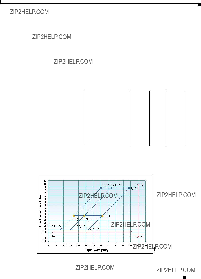
Figure 2-5 shows a graphical representation of an extended range power mask for an OPT-PRE card.
Figure 2-5 OPT-PRE Card Extended Range Power Mask
2.2.4.2 OPT-BST and OPT-BST-E Cards
Table 2-23 and Table 2-24 define all optical internal parameters and performance information for the OPT-BST and OPT-BST-E booster amplifier cards.
Cisco ONS 15454 DWDM Engineering and Planning Guide, Release 7.x
Chapter 2 Cards Specifications
2.2.4 Optical Amplifiers
Figure 2-6 shows a graphical representation of the power mask for the OPT-BST card.
Figure 2-6 OPT-BST Card Power Mask
Table 2-24 defines the power and gain specifications for the OPT-BST-E card.
Chapter 2 Cards Specifications
2.2.4 Optical Amplifiers
Figure 2-7 shows a graphical representation of standard extended gain range for the OPT-BST-E card.
Figure 2-7 OPT-BST-E Card Standard and Extended Gain Range
2.2.4.3 OPT-BST-L Card
The OPT-BST-L card is an L-band DWDM EDFA with OSC add/drop capability that can operate up to 64 optical transmission channels at 50-GHz channel spacing over the L band of the optical spectrum (wavelengths from 1570 nm to 1605 nm). To control gain tilt, the card is equipped with a built-in VOA managed by the card microprocessor. The OPT-BST-L provides the following features:
???True variable gain
???Fixed gain mode (with programmable tilt)
???Fast transient suppression
???Nondistorting low frequency transfer function
???Settable maximum output power
???Fixed output power mode (mode used during provisioning)
???Constant drive current mode (test mode)
???Amplified spontaneous emission (ASE) compensation in fixed gain mode
Cisco ONS 15454 DWDM Engineering and Planning Guide, Release 7.x
Chapter 2 Cards Specifications
2.2.4 Optical Amplifiers
???Full monitoring and alarm handling capability with settable thresholds
???Supported optical safety functionality by signal loss detection and alarm, fast power down control, and reduced maximum output power in safe power mode
The OPT-BST-L card implements the following optical safety functions:
???Optical Safety Remote Interlock (OSRI)
???Automatic Laser Shutdown (ALS)
The OSRI function provides hardware and software capability for shutting down or reducing the output optical power to a safer level, whereas the ALS function provides a safety mechanism (automatic power reduction [APR]) for fiber cuts.
Table 2-25 defines all power and gain specifications for OPT-BST-L card:
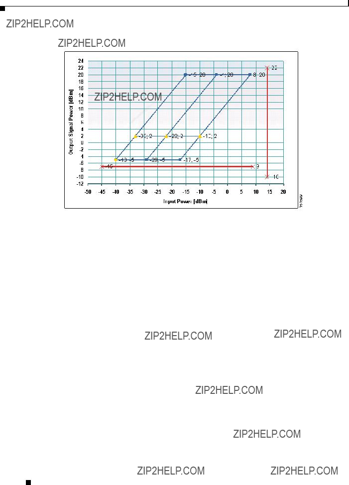
Figure 2-8 shows the standard and extended gain range for the OPT-BST-L card. Red lines indicate the total measurement range accomplished by the photodiodes.
Figure 2-8 OPT-BST-L Card Standard and Extended Gain Range
Cisco ONS 15454 DWDM Engineering and Planning Guide, Release 7.x
Chapter 2 Cards Specifications
2.2.4 Optical Amplifiers
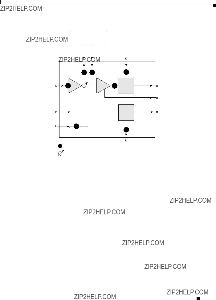
Figure 2-9 shows the internal functional structure for the OPT-BST-L card.
Figure 2-9 OPT-BST-L Card Functional Block Diagram
Optical loss (in dB) caused by the OPT-BST-L monitor ports is printed on the card faceplate. The OPT-BST-L is a single-slot bidirectional card with three LEDs and eight LC-PC-II optical connectors on the card faceplate.
2.2.4.4 OPT-AMP-L Card
The OPT-AMP-L preamplifier card can operate up to 64 optical transmission channels with 50-GHz channel spacing over the L-band optical spectrum (wavelengths from 1570 nm to 1605 nm). The OPT-AMP-L is an L-band DWDM optical amplifier module consisting of a two-stage EDFA with a MAL section for allocation of DCU and with the capability to add/drop the OSC. The OPT-AMP-L preamplifier is software configurable as a preamplifier or as a booster amplifier.
To control gain tilt, the card is equipped with a built-in VOA managed by the card???s microprocessor. The VOA can also be used to pad the DCU to a reference value.
The OPT-AMP-L card provides the following features:
???True variable gain
???Fast transient suppression
???Nondistorting low frequency transfer function
???Settable maximum output power
???Fixed Output Power mode (mode used during provisioning)
???Constant drive current mode (test mode)
???MAL support for a fiber-based DCU
???ASE compensation in Fixed Gain mode
???Full monitoring and alarm handling capability with settable thresholds
???Supported optical safety functionality by means of signal loss detection and alarm, fast power down control and reduced maximum output power in safe power mode
Cisco ONS 15454 DWDM Engineering and Planning Guide, Release 7.x
Chapter 2 Cards Specifications
2.2.4 Optical Amplifiers
The OPT-AMP-L card implements the following optical safety functions:
???OSRI
???ALS
The OSRI function provides hardware and software capability for shutting down optical power or reducing it to a safe level, whereas the ALS function provides an APR safety mechanism for fiber cuts.
Table 2-26 defines the standard and extended gain ranges for the OPT-AMP-L card.
Figure 2-10 shows a graphical representation of standard and extended gain range for the OPT-AMP-L card.
Cisco ONS 15454 DWDM Engineering and Planning Guide, Release 7.x
Chapter 2 Cards Specifications
2.2.4 Optical Amplifiers
Figure 2-10 OPT-AMP-L Card Standard and Extended Gain Range
Figure 2-11 shows the internal functional structure of the OPT-AMP-L card.
Cisco ONS 15454 DWDM Engineering and Planning Guide, Release 7.x
Chapter 2 Cards Specifications
2.2.5 Dispersion Compensation Units
Figure 2-11 OPT-AMP-L Card Functional Block Diagram
External Mid-Stage
Loss
The card faceplate shows the optical loss (in dB) of the monitor ports provided by the OPT-AMP-L card. The OPT-AMP-L is a double-slot card with three LEDs on the faceplate.
2.2.5 Dispersion Compensation Units
Dispersion compensation units (DCUs) are installed in the ONS 15454 dispersion compensation shelf when optical preamplifier (OPT-PRE or OPT-AMP-L) cards are installed in the DWDM node.
Table 2-27 lists the DCUs used with the ONS 15454 DWDM configuration.
Cisco ONS 15454 DWDM Engineering and Planning Guide, Release 7.x
Chapter 2 Cards Specifications
2.2.5 Dispersion Compensation Units
Each C-band DCU can compensate a maximum of 65 km of single-mode fiber (SMF-28). DCUs can be cascaded to extend the compensation to 130 km.
Cisco ONS 15454 DWDM Engineering and Planning Guide, Release 7.x
Chapter 2 Cards Specifications
2.2.5 Dispersion Compensation Units
2.2.5.1 DCU Mechanical Specifications
The DCU subrack is designed to comply with all international standards. The DCU shelf is housed in a 1-RU 19" (482.6mm)/23??? (584.2mm) rack-mounted shelf [17" (431.8mm) wide, 11" (279.4mm) deep, 1.75" (44.45mm) high] with all front access (fibers, management interfaces when applicable). The depth of the subrack, including cable management, does not exceed the 280 mm requirement.
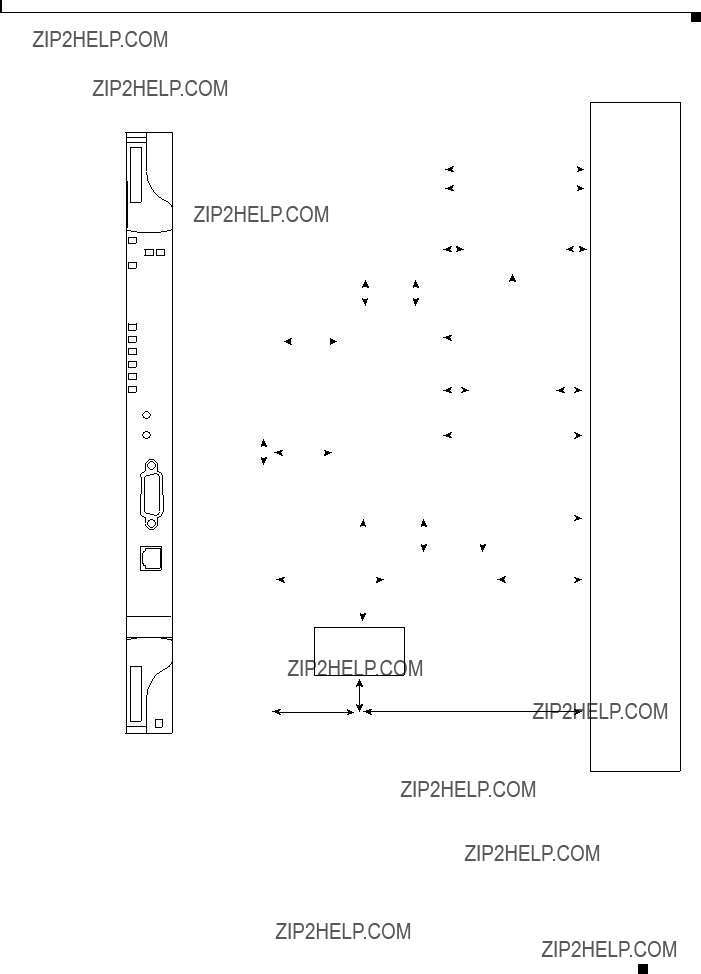
For a bidirectional DCU, shown in Figure 2-12, the dimensions are 8??? (205mm) wide, 9??? (230 mm) deep, and 1.5??? (38.5 mm) high.
The DCU has one optical adapter on its front panel that can house two LC-PC-II connectors.
151600
Refer to the Cisco ONS 15216 System Dispersion Compensation Unit User Guide for the
Cisco ONS 15216 DCU mechanical specifications.
2.2.5.2 DCU Optical Specifications
Table 2-28 shows the optical specifications for ONS 15454 DCUs.
Table 2-28 Optical Speci???cations for ONS 15454 DCUs
Cisco ONS 15454 DWDM Engineering and Planning Guide, Release 7.x
Chapter 2 Cards Specifications
2.2.6 Transponder, Muxponder, and Optical Cards
Table 2-28 Optical Speci???cations for ONS 15454 DCUs (continued)
2.2.6 Transponder, Muxponder, and Optical Cards
For DWDM system interoperability, the operating center frequency (wavelength) of channels must be the same at the transmitting and receiving ends. Channel selection (center frequency) and channel width determine the number of nonoverlapping channels in the spectrum. Channel width, wavelength, bit rate, fiber type, and fiber length determine the amount of dispersion. Channel separation allows for a frequency deviation of approximately 2 GHz, caused by frequency drifts in the laser, filter, and amplifier devices to avoid interchannel interference.
The ITU-T currently recommends 81 channels in the C band, starting from 1528.77 nm and incrementing in multiples of 50 GHz to 1560.61 nm.
All C-band TXP and MXP cards support a range of wavelengths in increments of 100 GHz, as shown in Table 2-29.
Chapter 2 Cards Specifications
2.2.6 Transponder, Muxponder, and Optical Cards
Cisco ONS 15454 DWDM Engineering and Planning Guide, Release 7.x
Chapter 2 Cards Specifications
2.2.6 Transponder, Muxponder, and Optical Cards
The TXP and MXP cards support the following L-band range of wavelengths in increments of 100 GHz.
Cisco ONS 15454 DWDM Engineering and Planning Guide, Release 7.x
Chapter 2 Cards Specifications
2.2.6 Transponder, Muxponder, and Optical Cards
Cisco ONS 15454 DWDM Engineering and Planning Guide, Release 7.x
Chapter 2 Cards Specifications
2.2.6 Transponder, Muxponder, and Optical Cards
2.2.6.1 OC48 ITU-T Optics
The Cisco ONS 15454 supports a range of wavelengths in increments of 100 GHz and 200 GHz with its OC48 ITU-T optics, as shown in Table 2-31.
Chapter 2 Cards Specifications
2.2.6 Transponder, Muxponder, and Optical Cards
Cisco ONS 15454 DWDM Engineering and Planning Guide, Release 7.x
Chapter 2 Cards Specifications
2.2.6 Transponder, Muxponder, and Optical Cards
The ONS 15454 OC48 ITU-T cards provide you with 37 separate ITU-T channels to choose from. These wavelengths conform to ITU-T 100-GHz and 200-GHz channel spacing, enabling compatibility with most DWDM systems. Integrating the ONS 15454 OC48 ITU-T cards with third-party DWDM products enables you to design a low-cost, scalable DWDM system with full add/drop capabilities.
2.2.6.2 OC192 ITU-T Optics
Table 2-32 lists the OC192 ITU-T channels available for the ONS 15454.
Chapter 2 Cards Specifications
2.2.6 Transponder, Muxponder, and Optical Cards
1. These wavelengths are shorter lead-time cards and are recommended for deployment.
The ONS 15454 offers eight OC192 ITU-T cards. Each card provides a long-reach SONET compliant 9.95328 Gbps high-speed interface operating at a 100-GHz spaced, ITU-T compliant wavelength within the 1530 to 1562 nm frequency band. The primary application for the OC192 ITU-T card is for use in ultra high-speed metro interoffice facility (IOF) solutions interconnecting central offices and collocation sites over a DWDM-based transport network.
2.2.6.3 Client Side Interfaces
The TXP and MXP cards utilize small form-factor pluggables (SFPs) and 10-Gigabit SFPs (XFPs) to accommodate various client interface payloads. The SFP and XFP modules are inserted into matching connectors on the front panels of the cards and then connected to the client equipment with fiber-optic cables. Table 2-33 shows the SFP and XFP pluggable client modules available for each client service type.
Cisco ONS 15454 DWDM Engineering and Planning Guide, Release 7.x
Chapter 2 Cards Specifications
2.2.6 Transponder, Muxponder, and Optical Cards
Cisco ONS 15454 DWDM Engineering and Planning Guide, Release 7.x
Chapter 2 Cards Specifications
2.2.7 Y-Cable Module
For more information on SFPs and XFPs, refer to the ???SFP Specifications??? and ???XFP Specifications??? sections in Cisco ONS 15454 DWDM Reference Manual.
2.2.7 Y-Cable Module
The two types of Y-cable module are the multimode splitter module and the single-mode splitter module. Both module types have 6 optical LC-LC adapters on the front panel. The adapter position and labeling are depicted in Figure 2-13.
Cisco ONS 15454 DWDM Engineering and Planning Guide, Release 7.x
Chapter 2 Cards Specifications
2.2.7 Y-Cable Module
Figure 2-13 Multimode Y-Cable Splitter Module
Table 2-34 shows operating parameters for a multimode Y-cable module.
Table 2-35 shows operating parameters for the single-mode Y-cable module.
Chapter 2 Cards Specifications
2.2.8 Mechanical Equipment
2.2.8 Mechanical Equipment
The following section describes mechanical equipment such as the bay frame, optical shelf, dispersion compensation shelf, Y-cable shelf, fiber storage units, and 32-channel patch-panel units.
2.2.8.1 Bay Frame
DWDM cards use a generic standard bay frame, which is compliant with ANSI Standard Seismic 19-inch and 23-inch Bay Frames (Telcordia GR-63-CORE) and/or ETSI 600 mm x 300 mm (ETS 300-119, ETS 300-019, CEI EN 60917 and IEC 61587).
Floor mounting depends on the frame or cabinet that the customer chooses.
2.2.8.2 Optical Shelf
The shelf assemblies used in the ONS 15454 DWDM system and SONET/SDH systems are the same. The ONS 15454 is simple to engineer and flexible, in order to reduce the equipping rules as much as possible.
The system dimensions for an ONS 15454 ETSI rack are 617 mm(18.17???) high x 432 mm (17???) wide x 280 mm (11???) deep. The dimensions of the ANSI system are 18.1??? (461.6 mm) high x 17???(431.8 mm) wide x 12???(305.0 mm) deep. A total of four shelves fit into a standard ANSI rack. A total of three shelves fit into ETSI racks.
The subrack has 17 card slots, which are numbered from 1 starting at the left. Each slot is labeled with an icon that must match the icon on the plug-in card???s faceplate. This enables easy identification of card/slot compatibility. Slots 7 through 11, indicated in white, are dedicated to system operations. These slots are known as common-control card slots. Slots 1 through 6 and 12 through 17, indicated in yellow and blue, are dedicated to traffic cards, such as OSC cards, optical add/drop cards, optical amplifier cards, and transponder/muxponder cards.
2.2.8.3 Dispersion Compensation Shelf
The dispersion compensation shelf is 1 RU in height. Two DCUs (one for each direction) can be housed in the dispersion compensation shelf. The shelf is not powered or cooled because the DCUs are optically passive.
2.2.8.4 Y-Cable Shelf
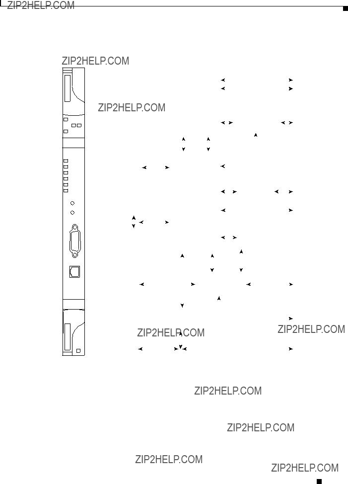
The Y-cable shelf houses up to eight Y-cable modules and all relevant patchcords. The Y-cable shelf has a height of 2 RU and can be installed in 19???(482.6 mm) ANSI or ETSI racks. See Figure 2-14.
Cisco ONS 15454 DWDM Engineering and Planning Guide, Release 7.x
Chapter 2 Cards Specifications
2.2.8 Mechanical Equipment
Figure 2-14 Y-Cable Shelf Fiber Routing
Y cable modules
144678
LC-LC cables
2.2.8.5 Fiber Storage
The fiber storage tray has height of 1 RU and can be installed in 19??? (482.6 mm) ANSI or ETSI racks.The fiber storage tray manages all incoming and outgoing fibers for a single ONS 15454 shelf. The minimum fiber bend radius is 1.5??? (38.1 mm) or 20 times the cable diameter at any point, whichever is greater.
For more information on fiber management, refer to the Cisco ONS 15454 DWDM Reference Manual.
2.2.8.6 32 Channel Patch-Panel Trays
The ONS 15454 offers two patch panel trays that can be installed in 19??? (482.6 mm) ANSI or ETSI shelves. The regular tray (15454-PP-64-LC) is 1 RU in height, and the deep tray is (PP-64) is 2 RU in height.
The deep patch panel tray (PP-64) manages the 32 channels that interconnect a ROADM node to relevant TXPs.
Table 2-35 shows fiber routing on the deep patch panel tray.
Cisco ONS 15454 DWDM Engineering and Planning Guide, Release 7.x
Chapter 2 Cards Specifications
2.2.8 Mechanical Equipment
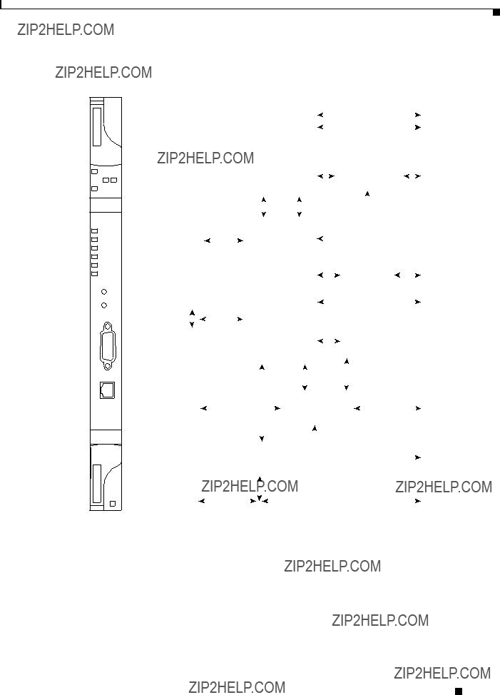
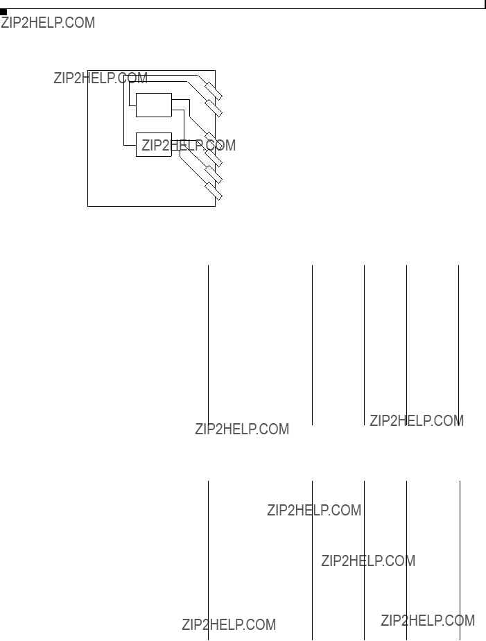
Figure 2-15 32-Channel Patch Panel Shelf Fiber Routing
151601
The PP-64 contains 64 LC-LC adapters and manages up to eight multifiber cables. The minimum fiber bend radius is 1.5??? (38.1 mm) or 20 times the cable diameter at any point, whichever is greater.
The PP-64 is used for both C-band and L-band systems. A label on the front panel enables identification of channel wavelength IDs during installation.
Cisco ONS 15454 DWDM Engineering and Planning Guide, Release 7.x
Chapter 2 Cards Specifications
2.2.8 Mechanical Equipment
Cisco ONS 15454 DWDM Engineering and Planning Guide, Release 7.x