C H A P T E R 1
Cisco CRS-1 Carrier Routing System
This site planning guide describes how to plan and prepare your site facilities for the installation of a Cisco CRS-1 Carrier Routing System 8-Slot Line Card Chassis (also referred to in this document as the ???Cisco CRS-1 8-slot line card chassis???). The guide provides a brief description of the chassis and its components, and basic site facilities requirements.
This guide describes all power, cooling, and environmental specifications to consider before ordering and installing the Cisco CRS-1 8-slot line card chassis. This guide also describes site facilities requirements, such as floor space, weight requirements, receiving and staging, and installation information to help you plan the site where the routing system will be installed.
Tip The installation of a CRS-1 8-slot line card chassis may require space, floor loading, power, and cooling modifications to a facility; therefore, you should plan the site well in advance of the scheduled delivery of the system.
The Cisco CRS-1 Carrier Routing System replaces much of the equipment in service provider points of presence (POPs) today. The routing systems are built around a scalable, distributed three-stage switch fabric and a variety of line card (packet) interfaces. These packet interfaces are located on modular services cards (MSCs) and their associated physical layer interface modules (PLIMs), which are effectively cross-connected to each other through the switch fabric.
???The Cisco CRS-1 8-slot line card chassis is a half-height, rack-mounted version of the 16-slot chassis. It is a highly scalable routing system that provides 640 gigabits per second (Gbps) of routing capacity and supports up to 8 MSCs. The chassis installs in a 19-inch equipment rack.
The Cisco CRS-1 8-slot line card chassis can be installed in colocation facilities, data centers, and many Tier II and Tier III locations. The routing system consists of a single rack-mounted chassis that contains the system components:
???Modular services cards (MSCs), also called line cards (up to eight)
???Physical layer interface modules, or PLIMs (up to eight, one for each MSC)
???Route processor (RP) cards (up to two)
???Switch fabric cards (four required)
???A chassis midplane that connects MSCs to their PLIMs and to switch fabric cards The Cisco CRS-1 8-slot line card chassis has its own power and cooling subsystems.
Cisco CRS-1 Carrier Routing System 8-Slot Line Card Chassis Site Planning Guide
Chapter 1 Cisco CRS-1 Carrier Routing System
The Cisco CRS-1 8-Slot Line Card Chassis
The Cisco CRS-1 8-Slot Line Card Chassis
The Cisco CRS-1 8-slot line card chassis is the main component of the Cisco CRS-1. The chassis is a mechanical enclosure that contains a chassis midplane. The midplane holds the system modular services cards (MSCs), their associated physical layer interface modules (PLIMs), and switch fabric cards. The chassis is mounted in a 19-inch equipment rack. See the ???Equipment Rack Considerations??? section on page 4-3 for more information.
This section describes the main components of the Cisco CRS-1 8-slot line card chassis. It primarily identifies the components that are considered field-replaceable units (FRUs), but where additional detail is useful identifies subassemblies that are not field replaceable.
The following figures show the Cisco CRS-1 8-slot line card chassis from both the front (PLIM) and rear (MSC) sides.
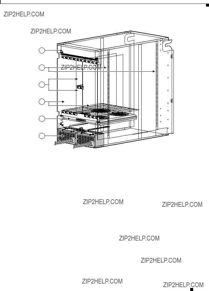
Figure 1-1 Front (PLIM) View of the 8-Slot Line Card Chassis
Cisco CRS-1 Carrier Routing System 8-Slot Line Card Chassis Site Planning Guide
Chapter 1 Cisco CRS-1 Carrier Routing System
The Cisco CRS-1 8-Slot Line Card Chassis
Figure 1-2 Rear (MSC) View of the 8-Slot Line Card Chassis
Chassis Components
The Cisco CRS-1 8-slot line card chassis contains the following components:
???As many as eight modular services cards (MSCs), also called line cards, and eight physical layer interface modules (PLIMs). The MSC and PLIM are an associated pair of cards that mate through the chassis midplane. The MSC provides the forwarding engine for Layer 3 routing of user data, and the PLIM provides the physical interface and connectors for the user data.
The MSC can be associated with several different PLIMs, which provide different interface speeds and technologies. The available PLIMs are as follows:
???1-port OC-768c/STM-256c packet-over-SONET (POS). Available with short-reach (SR) optics.
???4-port OC-192c/STM-64c POS/DPT. Available with long-reach (LR), intermediate-reach (IR), short-reach (SR), and very-short-reach (VSR) optics.
???OC-48c/STM-16c POS/DPT, configurable with 1 to 16 ports. Available with long-reach (LR) and short-reach (SR) optics. This PLIM supports pluggable optics.
???10-Gigabit Ethernet (GE. Available in long-reach (LR) optics. This PLIM supports pluggable optics, and can be configured with 1 to 8 ports.
Cisco CRS-1 Carrier Routing System 8-Slot Line Card Chassis Site Planning Guide
Chapter 1 Cisco CRS-1 Carrier Routing System
The Cisco CRS-1 8-Slot Line Card Chassis
???Cisco CRS-1 SPA Interface Processor-800. Occupies one physical-layer-interface-module (PLIM) slot on the Cisco CRS-1 16- and 8-Slot Line Card Chassis. Supports six normal-height SPAs or three double-height SPAs or any combination in between.
???A chassis midplane. The midplane connects MSCs to their associated PLIMs and allows an MSC to be removed from the chassis without having to disconnect the cables that are attached to the associated PLIM. The midplane distributes power, connects the MSCs to the switch fabric cards, and provides control plane interconnections. The midplane is not field replaceable by the customer.
???One or two route processor cards (RPs). The RPs provide the intelligence of the system by functioning as the line card chassis system controller and providing route processing. Only one RP is required for system operation. For redundant operation, you can order a second, redundant RP as an option (CRS-8-RP/R). When two RPs are used, only one RP is active at a time. The second RP acts as a ???standby??? RP, serving as a backup if the active RP fails.
The RP also monitors system alarms and controls the system fans. LEDS on the front panel indicate active alarm conditions.
???Upper and lower fan trays. The fans pull cool air through the chassis. A removable air filter is located below the PLIM card cage at the front of the chassis. Each fan tray contains three fans.
???Four half-height switch fabric cards. These cards provide the three-stage Benes switch fabric (S1/S2/S3) for the routing system. The switch fabric performs the cross-connect function of the routing system, connecting every MSC (and its associated PLIM) with every other MSC (and its associated PLIM) in the system.
The switch fabric receives user data from one MSC and PLIM pair and performs the switching necessary to route the data to the appropriate egress MSC and PLIM pair. The switch fabric is divided into eight planes that evenly distribute the traffic across the switch fabric. Each switch fabric card implements two planes of the switch fabric.
???A power system that provides redundant power to the chassis. The power system consists of two AC or DC power distribution units (PDUs) and two AC rectifier modules or two DC power entry modules (PEMs), one for each PDU. Each PDU supplies input power to a rectifier or PEM, which in turn provides processed power to the chassis. Each DC and AC power module contains a removable air filter, located on the back of the module.
The PLIM side of the chassis is considered the front of the chassis, where user data cables attach to the PLIMs and cool air enters the chassis. The MSC side, which is where warm air is exhausted, is considered the rear of the chassis.
Chassis Slot Numbers
The following figure shows the slot numbers on the front and back of the chassis.
Cisco CRS-1 Carrier Routing System 8-Slot Line Card Chassis Site Planning Guide
Chapter 1 Cisco CRS-1 Carrier Routing System
The Cisco CRS-1 8-Slot Line Card Chassis
Figure 1-3 Cisco CRS-1 8-Slot Line Card Chassis Slot Numbers
122777
As shown, the front (PLIM) side of the chassis has the following card slots:
???Eight PLIM slots (left to right: 0, 1, 2, 3...4, 5, 6, 7)
???Two route processor card slots (RP0 and RP1)
The rear (MSC) side of the chassis has the following card slots:
???Eight MSC slots (left to right: 7, 6, 5, 4...3, 2, 1, 0)
???Four half-height switch fabric card slots (SM0, SM1, SM2, and SM3)
Notice that the PLIM and MSC slot numbers are reversed. This reversal is because each MSC mates with its associated PLIM through the midplane. For example, the PLIM in slot 0 (far left on the chassis front) mates through the midplane with the MSC in slot 0 (far right on the chassis rear).
Cisco CRS-1 Carrier Routing System 8-Slot Line Card Chassis Site Planning Guide
Chapter 1 Cisco CRS-1 Carrier Routing System
The Cisco CRS-1 8-Slot Line Card Chassis
Cisco CRS-1 Carrier Routing System 8-Slot Line Card Chassis Site Planning Guide