Cisco SFS 3001 Multifabric Server Switch
Quick Start Guide (Topspin 90 Quick Start Guide)
Release 2.1.0
Part Number:
Product ID: 140252
Cisco SFS 3001 Multifabric Server Switch
Quick Start Guide (Topspin 90 Quick Start Guide)
Release 2.1.0
Part Number:
Product ID: 140252
Copyright ??
The Topspin Switched Computing System, Topspin Host Channel Adapter, Topspin Element Manager, and collateral software programs and documentation are subject to and made available only pursuant to the license agreement signed by you and Topspin, Communications, Inc. (or if no signed license agreement exists, the license agreement included with your original media) and may only be used in accordance with the terms of that agreement. Making copies, modifications, or compilation works of the software except as specifically allowed in that agreement is prohibited by law and constitutes a punishable violation of the law. This documentation may not be copied, modified or reduced to any electronic or
As defined in FAR section 2.101, DFAR section
This documentation may include technical inaccuracies or typographical errors and is subject to correction and other revision without notice. TOPSPIN PROVIDES THIS DOCUMENTATION "AS IS" AND WITHOUT ANY
WARRANTIES OF ANY KIND, EITHER EXPRESS OR IMPLIED, INCLUDING BUT NOT LIMITED TO THE IMPLIED WARRANTIES OF MERCHANTABILITY OR FITNESS FOR A PARTICULAR PURPOSE. Some states or jurisdictions do not allow disclaimer of express or implied warranties in certain transactions; therefore, this statement may not apply to you.
??Copyright
Document Version: 2.1.0
Part Number:
Product ID: 140252
Printed in the United States of America.
iii
Contents

v
Regulatory Notices
FCC Statement
This equipment has been tested and found to comply with the limits for a Class A digital device, pursuant to Part 15 of the FCC Rules. These limits are designed to provide reasonable protection against harmful interference when the equipment is operated in a commercial environment. This equipment generates, uses, and can radiate radio frequency energy and, if not installed and used in accordance with the instruction manual, may cause harmful interference to radio communications. Operation of this equipment in a residential area is likely to cause harmful interference in which case the user will be required to correct the interference at his own expense.
Safety Information
??????Electrical Cautions??? on page v
??????General Cautions??? on page vii
??????Laser Cautions??? on page vii
Electrical Cautions
Use only the power cable provided with your Topspin system. Inspect the power cord and determine if it provides the proper plug and is appropriately certified for use with your electrical system. Discard the cord if it is inappropriate for your country???s electrical system and obtain the proper cord, as required by your national electrical codes or ordinances.
CAUTION: Grounding is supplied by the

vi
Ensure the ground connection on the power supply is correct and functioning before applying power to the Topspin system.
CAUTION: Always ground yourself before touching any internal Topspin system components to avoid damage from electrostatic discharge (ESD).
CAUTION: The Topspin system has two power cables. The operator must disconnect all power cables before attempting to remove the system from the rack.
CAUTION: Remove power cables by grasping the cable connector and pulling straight out.If the chassis comes equipped with a
CAUTION: The Topspin system contains lithium batteries. Do not attempt to replace or discard these batteries. The batteries may only be serviced by Topspin service personnel.
CAUTION: Observe and follow service markings. Do not service the Topspin system, except as explained in the Topspin documentation supplied with your system. Opening the chassis or removing the enclosure cover exposes you to electrical shock and may damage system components.
If one or more of the following situations occurs, remove power to the Topspin system chassis, and contact your Topspin support representative:
???The power cable or power plug is damaged.
???The system has been exposed to water.
???The system has been dropped or damaged in any way.
???The system does not operate correctly after following the installation instructions.
CAUTION: You must ensure the operating environment has adequate air circulation. Keep the Topspin in a cool,
CAUTION: Use only
vii
CAUTION: Never place your hand inside an empty card or module bay. You should never have cause to place a hand anywhere inside the Topspin chassis. Unused card and module bays should always have a Topspin cover over the bay to ensure proper safety, ventilation, and cooling.
General Cautions
CAUTION: No user is authorized to remove the Topspin system enclosure cover. The internal chassis contains no
CAUTION: Opening and/or modifying expansion and system modules may void your warranty. Refer to your warranty to determine access restrictions.
In general:
???Do not spill food or liquids on your system components.
???Protect your Topspin system from sudden
???Place cables appropriately so that they do not obstruct any egress within the data center and they do not block any ventilation inlets or outlets.
???Rack mount the Topspin chassis according to the rack manufacturer recommendations.
Laser Cautions
CAUTION: Only qualified service technicians should repair laser devices.
CAUTION: Only open, modify, or service laser devices as specified in the manufacturer documentation.
CAUTION: Use of controls or adjustments or performance of procedures other than those specified herein may result in hazardous laser radiation exposure.
CAUTION: In order to ensure eye safety, only the

viii
Laser Specs
Table
* Standards used: CDRH - 21CFR Chapter I ??1040.10; IEC -
Contact Information
Table

1
1
Topspin 90 Quick Start
This document describes the basic steps required to install and configure the Topspin 90 system.
For more detailed information about the Topspin 90 server switch, we recommend that you have the
Topspin 90 Hardware Guide available.
??????Prepare the Site??? on page 1
??????Install the Topspin 90 in an Equipment Rack??? on page 2
??????Install Expansion Modules (Optional)??? on page 5
??????Cable the Switch??? on page 5
??????Configure Basic Connectivity??? on page 6
??????Connect and Configure InfiniBand Hosts??? on page 8
??????Install the Element Manager (GUI)??? on page 10
??????Launch Chassis Manager??? on page 11
??????Configure Additional Settings??? on page 12
??????(Optional) Configure the Ethernet Gateway??? on page 13
??????Configure the Fibre Channel Gateway (Optional)??? on page 15
Prepare the Site
1.Read the cautionary statements in ???Safety Information??? on page v.
2.Unpack the Topspin 90 package, using the packing list provided.
3.Register the Topspin system online. Go to http://topspin.com/support/.
4.Prepare a management workstation, such as a PC or laptop running a terminal program, and a

2
5.Prepare the physical environment for the Topspin 90.
a.Make sure that you have an approved grounding
b.Make sure the system has the right cables and sufficient ventilation.
c.Unpack the Topspin 90 package, using the packing list provided.
d.Verify that you have all of the items on the Requirements list. See ???Requirements??? on page 2.
Install the Topspin 90 in an Equipment Rack
There are two different methods that can be used to rack the Topspin 90. This guide provides instructions for one method. To view instructions on the alternative method, refer to the Topspin 90 Hardware Guide.
Requirements
In addition to the accessories provided with the switch, you should have:
???Phillips screw driver
???Eight screws and any associated mounting clips to secure the brackets to your rack (2 for each rail of the rack)
???Two people are recommended to perform the install
Prepare for the Installation
1.Open the shipping package, if you have not already done so. Remove the chassis, rack brackets,
2.Place the chassis on a secure, clean surface.
3.Open the plastic bag containing mounting parts.
4.Check the slot in the rack for sufficient clearance.
5.Determine the direction that the switch will be installed and justified in the rack. The direction that you mount the switch will determine the direction that the brackets will need to be attached.
Rack Mount Installation
NOTE: There are two different ways to perform the rack installation of the Topspin 90. In this procedure, you will attach the rails to the rack before inserting the switch. This procedure is slightly easier to perform if you only have one person. Refer to the Topspin 90 Hardware Guide to view the second installation method.
3
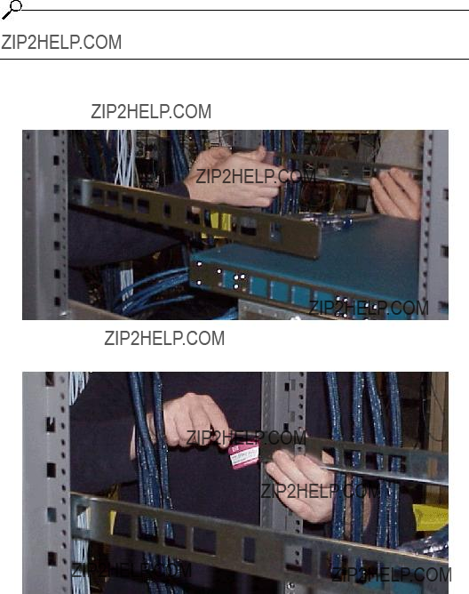
1.Take one connected pair of rack brackets and separate them. Each side arrives assembled to its counterpart, but should be separated before attaching to the switch when using this method of installation.
Separate Brackets
Figure
2.Attach the rack bracket that has screw holes to the side of the chassis with the flange facing away from the switch, as shown in Figure
The standard method is to face the flange toward the front of the chassis. However, you can also mount the flange toward the back if you want to mount the switch backward in the chassis
Flange
Figure
3.Repeat step 1 and step 2 for the other side of the switch chassis.
NOTE: The two counterparts to these sliding rails (without screw holes) should still be unattached.
4.Check your rack for clearance for the switch. The switch can be installed either directly on top of another device (using the rubber feet, which are provided), or be suspended from the rack brackets.
4
5.Attach the remaining two rail brackets to your rack.
a.Orient a bracket toward the back of the rack with the flange facing away from the rack. The flange should go around the outside of the rack post, as shown in, as shown in Figure
NOTE: If you are mounting the switch backward, the rack bracket should be installed toward the front of the rack.
b.Secure the brackets with your screws through the back of the rack posts, as shown in Figure
c.Repeat on both sides of the rack.
Figure
Figure
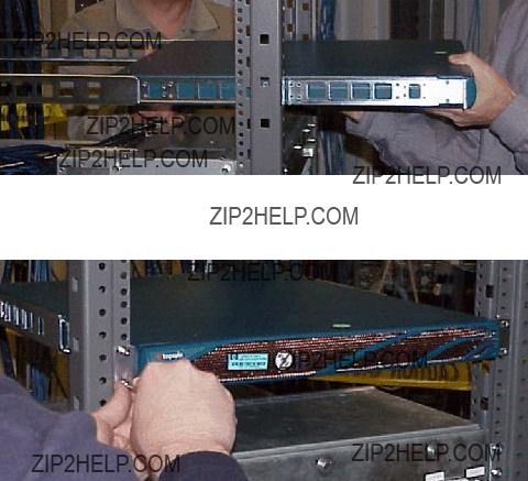
6.Lift the switch unit and align the bracket on the switch with the bracket on the rack before sliding the two sets of brackets together.
7.Carefully push the switch unit into the rack.
5
If the brackets do not slide easily, the alignment may be off. Pull the switch back toward you and realign the brackets.
Figure
8.Secure the switch with your screws through the front of the rack, as show in Figure
Figure
Install Expansion Modules (Optional)
1.Install any optional Fibre Channel or Ethernet Gateway modules.
2.Install all hardware components before the Topspin 90 is powered on.
3.A gateway module or blanking panel must always be installed.
Cable the Switch
Connect Management Ports
1.Connect one end of the
2.Connect the other end of the serial cable to your terminal server or management workstation.
3.Connect an Ethernet cable to the Ethernet port (bottom port).
4.Check the LEDs on the Management ports. The link status should be lit.

6
Connect InfiniBand Cables
1.Plug InfiniBand Cables from the
2.Plug InfiniBand cables from the Topspin 90 to any additional InfiniBand switches that you want to connect.
(Optional) Connect to Ethernet Devices
1.Connect the optional Ethernet gateway to workstations, routers or switches. The Ethernet gateway
(Optional) Connect to Fibre Channel Devices
1.Connect the optional Fibre Channel gateway to Fibre Channel storage arrays or switches with fibre cabling. Standard LC pluggable connectors are required.
Connect the Power Cable
1.Insert the power cords to the power jacks on the rear of the chassis.
2.Plug the other end of each AC power cable into an outlet operating at 90 - 132 VAC or
3.Check the System LED on the chassis to see if it is green. It will be blinking yellow/green until the
Configure Basic Connectivity
1.Configure an IP address for the Ethernet Management port.
It is necessary to configure connectivity to the
IP addresses can be assigned statically (which is the default), or dynamically assigned using DHCP.
??????Assigning an Address Statically??? on page 6
??????Assigning an Address Dynamically (DHCP)??? on page 7
Assigning an Address Statically
Refer to the static example below:
a.When the system has completed booting, press <Enter> several times to display the CLI prompt.
Login:
b.Enter the user name and password. The default user name is super, and the default password is super.
Login: super
Password: super
7
c.Enter the enable command.
d.Enter the configure command.
e.Enter the interface
f.Enter the IP address of the management port followed by the netmask.
g.Set the default gateway for the management port. For example:
h.Enable the management port by entering the no shutdown command.
i.Save the configuration to preserve it between reboots.
Assigning an Address Dynamically (DHCP)
The Topspin 90 supports dhcp to assign the IP address.
a.When the system has completed booting, press <Enter> several times to display the CLI prompt.
Login:
b.Enter the user name and password. The default user name is super, and the default password is super.
Login: super
Password: super
c.Enter the enable command.
d.Enter the configure command.
e.Enter the interface

8
f.Enter the option dhcp command. The chosen method will be persistent across module reboots.
g.Enable the management port by entering the no shutdown command.
h.Save the configuration to preserve it between reboots.
i.Use the show interface
===============================================================
===============================================================
Connect and Configure InfiniBand Hosts
This section describes a brief overview for configuring your InfiniBand hosts. For more detailed instructions, please see the HCA/Host Side Drivers Users Guide for Linux, which is included with your HCA(s).
If you are installing windows drivers, refer to the HCA Users Guide for Windows.
1.Install the HCA(s).
a.Power down the host system following proper grounding procedures.
b.Unpack the HCA card and insert it into an open
2.Power on the host system.
3.Install the HCA driver(s).
An integrated suite of drivers is provided, including IPoIB, SRP, SDP, uDAPL and MPI.
a.Make sure your Linux kernel is supported. Refer to the Topspin Web site for a list of supported versions.
b.Insert the supplied
c.(Optional) Mount the
# mount /mnt/cdrom
9
d.Open a terminal or graphic window and access the
e.Execute the command ./tsinstall in a terminal window. This program automatically detects the available kernel and installs the appropriate drivers as RPM packages. By default, topspin files are saved in the /usr/local/topspin directory.
#cdmount ./tsinstall
4.Configure the HCA drivers.
a.Configure the IPoIB driver by assigning an IP address to interface ib0 and/or ib1, which corresponds to the two HCA ports. IPoIB drivers load when the interfaces are used for the first time.
To assign ib interfaces, enter ifconfig ib#
Example of One HCA
#ifconfig ib0 192.168.0.0 netmask 255.255.255.0
#
# ifconfig ib1 192.168.0.1 netmask 255.255.255.0
#
Example of Two HCAs
#ifconfig ib0 192.168.0.0 netmask 255.255.255.0
#ifconfig ib1 192.168.0.1 netmask 255.255.255.0
#ifconfig ib2 192.168.0.2 netmask 255.255.255.0
#ifconfig ib3 192.168.0.3 netmask 255.255.255.0
a.(Optional) Configure MPI.
???Make sure that your connections to the HCA uses port 1 of the first HCA. MPI requires the use of HCA 1, port 1.
???Setup rsh or ssh on two nodes so that you can run commands between a remote and local node without entering a login or password. This is required to use the MPI protocol.
???Add paths to your environment PATH: /usr/local/topspin/mpi/mpich/bin /usr/local/topspin/bin
or
???Add the paths for all users by adding the following line to your /etc/profile.d script: export PATH=$PATH:/usr/local/topspin/mpi/mpich/bin:/usr/local/topspin/bin
b.Configure all other drivers, including SDP.
Refer to the Host Channel Adapter Installation Guide for instructions.
10
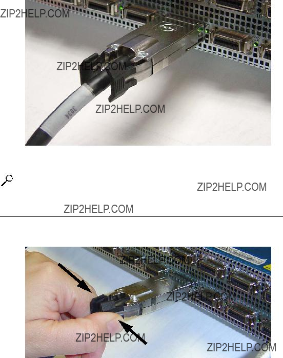
5.Plug InfiniBand Cables from the host to the InfiniBand switch.
a. To plug in an InfiniBand cable, push the connector into the interface until you hear/feel a click.
Figure
NOTE: If your host does not provide an ample amount of free space around a given IB port,
b.To remove a cable with a pinch connector, pinch both sides of the back of the connector and pull the connector away from the port.
Figure
Install the Element Manager (GUI)
1.Check that you have sufficient system resources. You will need the following:
???32 MB free RAM
???50 MB disk space + 50MB additional temporary space during installation

11
???300 Mhz processor
???800x600 screen resolution, 16bit color depth
2.Insert the Topspin
3.Access the top folder of the
???Linux/install_linux_ia64.bin
???Linux/install_linux_x86.bin
???Windows/install_x86.exe
???Solaris/install_solaris_sparc.bin
4.Run the installation wizard:
a.On Windows,
b.On Solaris and Linux systems, enter sh ./install_yourOS.bin.
5.Follow the
??? Enter location and preference information as requested by the installation program.
6.Start the Element Manager.
a.On Linux platforms, change to the installation directory and run the Element Manager with
./TopspinEM.
b.On Windows platforms, click
Programs
c.When prompted to enter a device name, enter the DNS host name or IP address of the Topspin 90, and community string for the unrestricted user. The default community string for the unrestricted user is secret.
Launch Chassis Manager
To launch Chassis Manager, perform the following steps:
1.Launch your Web browser.
Chassis Manager supports the following browsers
???Microsoft Internet Explorer version 6
???Netscape Navigator version 6
???Mozilla version 1.4
2.Type the Management IP address of your Server Switch in the address field of your browser and press Enter. (You configured the IP address in Step f.)
Figure
A
3.Enter your Server Switch user name and password in the

12
4.Chassis Manager loads in your browser window.
Figure
Configure Additional Settings
You can now fully manage the device with CLI over Telnet/SSH or the GUI.
1.Verify that you are running the latest version of software.
a.Refer to the Topspin support Web site: http://topspin.com/support/
b.Use the show version command in the CLI to show the current firmware version of your switch:
Login: super
Password: xxxxx
================================================================================
System Version Information
================================================================================
7:48:38
contact : support@topspin.com name :
location : 515 Ellis Street, Mountain View, CA 94043
action : none
result : none
2.(Optional) Configure time settings.
The Topspin 90 has internal clocks that are set at the factory.
You can also configure this manually or via NTP servers. If you do not want to configure the clock at this time, skip this step.
??? In the Element Manager GUI, go to
13
???In the CLI, enter the configuration mode and enter the ntp command with the IP address of the NTP server.
Example
3.Configure administrators and privilege levels. See Creating User Accounts in the User Guide.
(Optional) Configure the Ethernet Gateway
Configure the Ethernet Gateway if you have installed an Ethernet card into the chassis. Refer to the
Ethernet Gateway User Guide for more information.
There are three common topologies that can be deployed with Layer 2 Bridging:
???Bridging One Subnet.
???Action: Bridge one InfiniBand subnet to one IP subnet.
???Bridging Multiple Subnets
???Action: Bridge multiple IB and IP subnets across one gateway.
???Bridging Multiple Subnets across a single port
???Action: Bridge using VLAN tags and multiple subnets.
The following procedure describes the first topology: (bridging one subnet); this topology includes the following main steps:
???creating a
???creating a
For information regarding configuring
Layer 2 Bridging Procedure
Refer to the Ethernet Gateway User Guide for more options and more detailed steps.
1.Enable the Ethernet gateway
Enter the configure command in
Example
2.Create a
Enter
Leave the actual
Example
3.If you are using DHCP, enable broadcast forwarding.

14
Use the
Example
or
If you are not using DHCP, configure the next InfiniBand hop. Use the
Example
4.Specify the Ethernet Gateway to which you want to assign the new
???Enter interface ethernet slot/port
???Specify the new
Example
5.Specify the internal interface gateway to which you want to assign the new
The interface gateway number is the same as the physical slot number of the Ethernet gateway that you are configuring (in this example, the number is 2).
???Enter interface gateway physical slot#.
???Specify the new bridge group.
Example
6.Return to
???Enter exit.
???Enter exit.
???Enter show
Example
All configured
7.Configure the Ethernet hosts by entering ifconfig eth#
???Log in to the host as a root user.
???Enter ifconfig eth# subnet# netmask #
Example
# ifconfig eth1 61.0.0.0 netmask 255.255.0.0
Repeat for all Ethernet hosts.
15
Configure the Fibre Channel Gateway (Optional)
To configure ITLs, perform the following steps:
1.Log in to your host.
2.Enter the /etc/init.d/ts_srp stop command at the host CLI to force the host to log out of any storage. You must disable connections now and enable them later in this process.
3.Enter the /usr/local/topspin/bin/vstat
NOTE: Record the GUID value. You will enter it repeatedly.
4.Enter the no shutdown command on your Server Switch CLI to bring up any Fibre Channel gateway cards that connect your device to FC storage. The gateway automatically discovers all storage.
Example
5.(Optional) Enter the show fc srp target command to view the storage that your gateway(s) discovered.
Example
================================================================================
SRP Targets
================================================================================
wwpn: 21:00:00:04:cf:f6:c2:ab
wwnn: 20:00:00:04:cf:f6:c2:ab description: SRP.T10:21000004CFF6C2AB
6.Enter the fc srp initiator command with
???the GUID of the host (from step 3)
???the GUID extension (always 00:00:00:00:00:00:00:00)
???the
to configure your host.
NOTE: For an initiator to successfully connect to storage, each physical FC gateway port requires a virtual port with a unique WWPN that points to the initiator. Also, the initiator requires a unique WWNN. You can configure these values manually, but we strongly recommend that you take
16
advantage of CLI options to assign these values dynamically. The remainder of this process dynamically allocates WWNNs and WWPNs.
The
???Assigns a unique WWNN to the initiator.
???Creates a virtual port (that maps to the initiator) for all possible (actual & potential) physical FC gateway port and assigns a WWPN to each virtual port.
Example
7.(Optional) Enter the fc srp initiator command with
???the GUID of the host
???the GUID extension
???the description keyword
to assign an
Example

17
8.(Optional) Enter the show fc srp initiator command to verify the new initiator.
Example
================================================================================
SRP Initiators
================================================================================
guid: 00:05:ad:00:00:01:29:c5 extension: 00:00:00:00:00:00:00:00
description: Bender
wwnn: 20:01:00:05:ad:00:40:00 credit: 0
action:
result: success
wwpns: port wwpnfc-addr 2/1 20:01:00:05:ad:20:40:00 00:00:00 2/2 20:01:00:05:ad:24:40:00 00:00:00 3/1 20:01:00:05:ad:30:40:00 00:00:00 3/2 20:01:00:05:ad:34:40:00 00:00:00 4/1 20:01:00:05:ad:40:40:00 00:00:00 4/2 20:01:00:05:ad:44:40:00 00:00:00 5/1 20:01:00:05:ad:50:40:00 00:00:00 5/2 20:01:00:05:ad:54:40:00 00:00:00 6/1 20:01:00:05:ad:60:40:00 00:00:02 6/2 20:01:00:05:ad:64:40:00 00:00:00 7/1 20:01:00:05:ad:70:40:00 00:00:00 7/2 20:01:00:05:ad:74:40:00 00:00:00 8/1 20:01:00:05:ad:80:40:00 00:00:00 8/2 20:01:00:05:ad:84:40:00 00:00:00 9/1 20:01:00:05:ad:90:40:00 00:00:00 9/2 20:01:00:05:ad:94:40:00 00:00:00
10/1 20:01:00:05:ad:a0:40:00 00:00:00 10/2 20:01:00:05:ad:a4:40:00 00:00:00 11/1 20:01:00:05:ad:b0:40:00 00:00:00 11/2 20:01:00:05:ad:b4:40:00 00:00:00 12/1 20:01:00:05:ad:c0:40:00 00:00:00 12/2 20:01:00:05:ad:c4:40:00 00:00:00 13/1 20:01:00:05:ad:d0:40:00 00:00:00 13/2 20:01:00:05:ad:d4:40:00 00:00:00 14/1 20:01:00:05:ad:e0:40:00 00:00:00 14/2 20:01:00:05:ad:e4:40:00 00:00:00
Total: 1 initiators.
9.Enter the fc srp initiator command with
???the GUID of the host
???the GUID extension of the host
???the
to prompt your device to discover the potential ITLs that your initiator can form.

18
NOTE: This command may take some time to execute.
Example
10.Enter the show fc srp itl command to display the potential ITLs and record the
Example
================================================================================
SRP ITL
================================================================================
guid: 00:05:ad:00:00:01:29:c5 extension: 00:00:00:00:00:00:00:00
:
00:00:00:00:00:00:00:00:00:00:00:00:00:00:00:00
:
00:00:00:00:00:00:00:00:00:00:00:00:00:00:00:00
:
00:00:00:00:00:00:00:00:00:00:00:00:00:00:00:00
Total: 1 itls.

19
NOTE: The
11.Enter the no fc srp itl command with
???the GUID of the host
???the GUID extension of the host
???the WWPN of the target (from step 10)
???the LUN ID of the storage disk (from step 10)
???the
???the restricted keyword
to configure the ITL through LUN masking.
Example
12.Enter the no fc srp it command with
???the GUID of the host
???the GUID extension of the host
???the WWPN of the target
???the
???the restricted keyword
???the all keyword or the ports you want to unmask
to grant the initiator
Example
13.Enter the no fc srp itl command with
???the GUID of the host
???the GUID extension of the host
???the WWPN of the target
???the LUN ID of the storage disk
???the
???the restricted keyword
???the all keyword or the ports you want to unmask
to grant the initiator
Example
14. Enter the /etc/init.d/ts_srp start command at the host.
20
15.Return to User Exec mode or Privileged Exec mode and enter the show fc srp itl command to verify that the ITL is active. Port numbers appear in the
Index