Cisco Video Surveillance 6400 IP Camera
Installation Guide
Americas Headquarters
Cisco Systems, Inc. 170 West Tasman Drive
San Jose, CA
USA http://www.cisco.com Tel: 408
800
Text Part Number:
Cisco Video Surveillance 6400 IP Camera
Installation Guide
Americas Headquarters
Cisco Systems, Inc. 170 West Tasman Drive
San Jose, CA
USA http://www.cisco.com Tel: 408
800
Text Part Number:
THE SPECIFICATIONS AND INFORMATION REGARDING THE PRODUCTS IN THIS MANUAL ARE SUBJECT TO CHANGE WITHOUT NOTICE. ALL
STATEMENTS, INFORMATION, AND RECOMMENDATIONS IN THIS MANUAL ARE BELIEVED TO BE ACCURATE BUT ARE PRESENTED WITHOUT
WARRANTY OF ANY KIND, EXPRESS OR IMPLIED. USERS MUST TAKE FULL RESPONSIBILITY FOR THEIR APPLICATION OF ANY PRODUCTS.
THE SOFTWARE LICENSE AND LIMITED WARRANTY FOR THE ACCOMPANYING PRODUCT ARE SET FORTH IN THE INFORMATION PACKET THAT
SHIPPED WITH THE PRODUCT AND ARE INCORPORATED HEREIN BY THIS REFERENCE. IF YOU ARE UNABLE TO LOCATE THE SOFTWARE LICENSE
OR LIMITED WARRANTY, CONTACT YOUR CISCO REPRESENTATIVE FOR A COPY.
The Cisco implementation of TCP header compression is an adaptation of a program developed by the University of California, Berkeley (UCB) as part of UCB???s public domain version of the UNIX operating system. All rights reserved. Copyright ?? 1981, Regents of the University of California.
NOTWITHSTANDING ANY OTHER WARRANTY HEREIN, ALL DOCUMENT FILES AND SOFTWARE OF THESE SUPPLIERS ARE PROVIDED ???AS IS??? WITH
ALL FAULTS. CISCO AND THE
LIMITATION, THOSE OF MERCHANTABILITY, FITNESS FOR A PARTICULAR PURPOSE AND NONINFRINGEMENT OR ARISING FROM A COURSE OF
DEALING, USAGE, OR TRADE PRACTICE.
IN NO EVENT SHALL CISCO OR ITS SUPPLIERS BE LIABLE FOR ANY INDIRECT, SPECIAL, CONSEQUENTIAL, OR INCIDENTAL DAMAGES, INCLUDING,
WITHOUT LIMITATION, LOST PROFITS OR LOSS OR DAMAGE TO DATA ARISING OUT OF THE USE OR INABILITY TO USE THIS MANUAL, EVEN IF CISCO
OR ITS SUPPLIERS HAVE BEEN ADVISED OF THE POSSIBILITY OF SUCH DAMAGES.
CCDE, CCENT, CCSI, Cisco Eos, Cisco HealthPresence, Cisco Ironport, the Cisco logo, Cisco Lumin, Cisco Nexus, Cisco Nurse Connect, Cisco Stackpower,
Cisco StadiumVision, Cisco TelePresence, Cisco Unified Computing System, Cisco WebEx, DCE, Flip Channels, Flip for Good, Flip Mino, Flip Video, Flip Video (Design), Flipshare (Design), Flip Ultra, and Welcome to the Human Network are trademarks; Changing the Way We Work, Live, Play, and Learn, Cisco Store, and Flip Gift Card are service marks; and Access Registrar, Aironet, AsyncOS, Bringing the Meeting To You, Catalyst, CCDA, CCDP, CCIE, CCIP, CCNA, CCNP, CCSP, CCVP, Cisco, the Cisco Certified Internetwork Expert logo, Cisco IOS, Cisco Press, Cisco Systems, Cisco Systems Capital, the Cisco Systems logo, Cisco Unity, Collaboration Without Limitation, EtherFast, EtherSwitch, Event Center, Fast Step, Follow Me Browsing, FormShare, GigaDrive, HomeLink, Internet Quotient, IOS, iPhone, iQuick Study, IronPort, the IronPort logo, LightStream, Linksys, MediaTone, MeetingPlace, MeetingPlace Chime Sound, MGX, Networkers, Networking Academy, Network Registrar, PCNow, PIX, PowerPanels, ProConnect, ScriptShare, SenderBase, SMARTnet, Spectrum Expert, StackWise, The Fastest Way to Increase Your Internet Quotient, TransPath, WebEx, and the WebEx logo are registered trademarks of Cisco Systems, Inc. and/or its affiliates in the United States and certain other countries.
All other trademarks mentioned in this document or website are the property of their respective owners. The use of the word partner does not imply a partnership relationship between Cisco and any other company. (0907R)
Any Internet Protocol (IP) addresses and phone numbers used in this document are not intended to be actual addresses and phone numbers. Any examples, command display output, network topology diagrams, and other figures included in the document are shown for illustrative purposes only. Any use of actual IP addresses or phone numbers in illustrative content is unintentional and coincidental.
Cisco Video Surveillance 6400 IP Camera Installation Guide
?? 2012 Cisco Systems, Inc. All rights reserved.

Preface
Overview
This document, Cisco Video Surveillance 6400 IP Camera Installation Guide, provides information about installing and deploying the Cisco Video Surveillance 6400
Organization
This manual is organized as follows:
Obtaining Documentation, Obtaining Support, and Security
Guidelines
For information about obtaining documentation, submitting a service request, and gathering additional information, see the monthly What???s New in Cisco Product Documentation, which also lists all new and revised Cisco technical documentation, at:
http://www.cisco.com/en/US/docs/general/whatsnew/whatsnew.html
Subscribe to the What???s New in Cisco Product Documentation as a Really Simple Syndication (RSS) feed and set content to be delivered directly to your desktop using a reader application. The RSS feeds are a free service and Cisco currently supports RSS version 2.0.
Cisco Video Surveillance 6400 IP Camera Installation Guide

Preface
Cisco Video Surveillance 6400 IP Camera Installation Guide

C H A P T E R 1
Overview
This chapter describes the Cisco Video Surveillance 6400
???IP Camera Physical Details, page
Introduction
The Cisco Video Surveillance 6400 IP camera offers 1080p HD resolution with superb image quality. The 6400 is a
The 6400 boasts
Aimed at outdoor surveillance, the 6400 features
With other advanced features such as 802.3af compliant PoE and micro SD/SDHC card for onboard storage, the 6400 is a
Cisco Video Surveillance 6400 IP Camera Installation Guide

Chapter 1 Overview
Package Contents
Package Contents
The Cisco Video Surveillance 6400 IP Camera package includes the following items:
???Cisco Video Surveillance 6400 IP camera (1)
???Mounting plate alignment sticker (1)
???Wall mount bracket with mounting plate (1)
???Waterproof connector assembly for RJ45 Ethernet enclosure (1)
???Waterproof connector assembly for power and I/O cables (1)
???Sun shield(1)
???Standoff screws (2)
???Screws (6)
???Double sided tape (1)
???Silica gel (1)
???Pad (1)
???Cisco pointer card (1)
???RoHS Document (1)
IP Camera Physical Details
Front View
Figure
Figure
1
2
3
Cisco Video Surveillance 6400 IP Camera Installation Guide

Chapter 1 Overview
IP Camera Physical Details
Back View
Figure
Figure
2


 3 1
3 1 


4
5
6
7
Cisco Video Surveillance 6400 IP Camera Installation Guide

Chapter 1 Overview
IP Camera Physical Details
General Purpose I/O Terminal Block
Figure
Figure
1 2 3 4 5 6 7 8
Note The maximum output load from pins 7 and 8 is 400mA.
Cisco Video Surveillance 6400 IP Camera Installation Guide
C H A P T E R 2
Camera Installation
This chapter provides information and instructions for installing the Cisco Video Surveillance 6400 IP Camera, and includes the following topics:
???Installation Guidelines, page
???Warnings Before Installation, page
???Installing the IP Camera, page
???Connecting External Power and I/O Cables, page
???Connecting a Waterproof Ethernet Cable, page
???Installing the Sun Shield, page
Installation Guidelines
This section describes how to install the IP camera. Before installing, review these guidelines:
???The IP camera requires a network cable and a connection to a standard 10/100BaseT router or switch. To power the IP camera with Power over Ethernet (PoE), a switch must be 802.3af compliant.
???If you are using the IP camera on a network connection that does not provide PoE, you must use a Cisco 12 VDC power adapter (Cisco part number
???If you are using an input device, output device, or pan/tilt control device, you must configure additional settings after installing and performing the initial set up of the IP camera before the external device can fully operate. For detailed information about these settings, see the Cisco Video Surveillance 6000 Series IP Camera Configuration Guide.
???If you do not connect an external device (input, output, or pan/tilt control) when you perform the following installation procedure, you can install any of these devices later.
Cisco Video Surveillance 6400 IP Camera Installation Guide
Chapter 2 Camera Installation
Warnings Before Installation
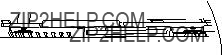
Warnings Before Installation
???Power off the Network Camera as soon as smoke or unusual odors are detected.
???Refer to your user's manual for the operating temperature.
Contact your distributor in the event of this happening.
???Do not place the Network Camera on unsteady surfaces.
???Do not insert sharp or tiny objects into the Network Camera.
???Do not touch the Network Camera during a lightning storm.
??? Do not drop the Network Camera.
Warning Installation of the equipment must comply with local and national electrical codes. Statement 1074
Warning The power supply must be placed indoors. Statement 331
Note If you use the IP camera outdoors, place the camera and the power supply in a suitable NEMA enclosure.
Cisco Video Surveillance 6400 IP Camera Installation Guide

Chapter 2 Camera Installation
Installing the IP Camera
Warning This product must be connected to a
Caution Inline power circuits provide current through the communication cable. Use the Cisco provided cable or a minimum 24AWG communication cable.
Note The power adapter that you use with the IP camera must provide power that is within
Note The equipment is to be connected to a Listed class 2, limited power source.
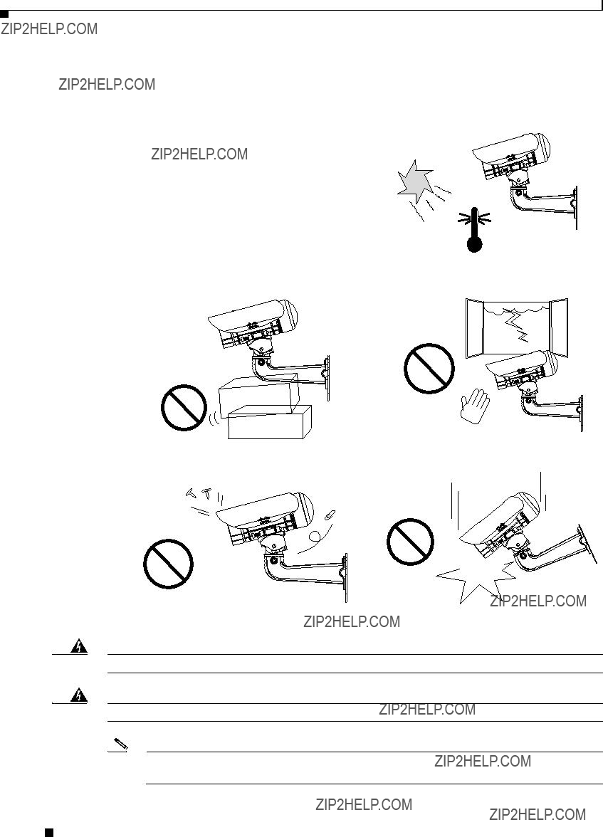
Installing the IP Camera
To install the Cisco Video Surveillance 6400 IP Camera, perform the following steps.
Note Use Figure
Procedure
Step 1 Attach the alignment sticker to the wall. Drill three mounting holes and one larger cabling hole into the wall, hammer the three included wall anchors into the holes, and secure the mounting plate with included screws.
Step 2 Attach the camera anchor bracket to the side of the IP camera with the two included screws.
Step 3 (Optional) If you want to use an external power source for the 6400 IP camera, or use external devices such as sensors and alarms, complete the steps in the ???Connecting External Power and I/O Cables??? section on page
Step 4 Feed the cable with an RJ 45 jack through the front opening of the wall mount bracket.
Step 5 Push the spring mortise and hook the camera anchor bracket onto the groove of the wall mount bracket.
Step 6 Secure the two screws on the other side of the wall mount bracket.
Step 7 Hang the wall mount bracket on the mounting plate.
Step 8 Secure the wall mount bracket to the mounting plate with the included screw.
Step 9 Connect the RJ45 jack to your network using an Ethernet cable, or to ensure a waterproof network connection, complete the steps in the ???Connecting a Waterproof Ethernet Cable??? section on page
Step 10 Adjust the angle of the wall mount bracket to achieve desired IP camera field of view.
Step 11 (Optional) Install the sun shield. For more information, see the ???Installing the Sun Shield??? section on page
Cisco Video Surveillance 6400 IP Camera Installation Guide
Chapter 2 Camera Installation
Installing the IP Camera
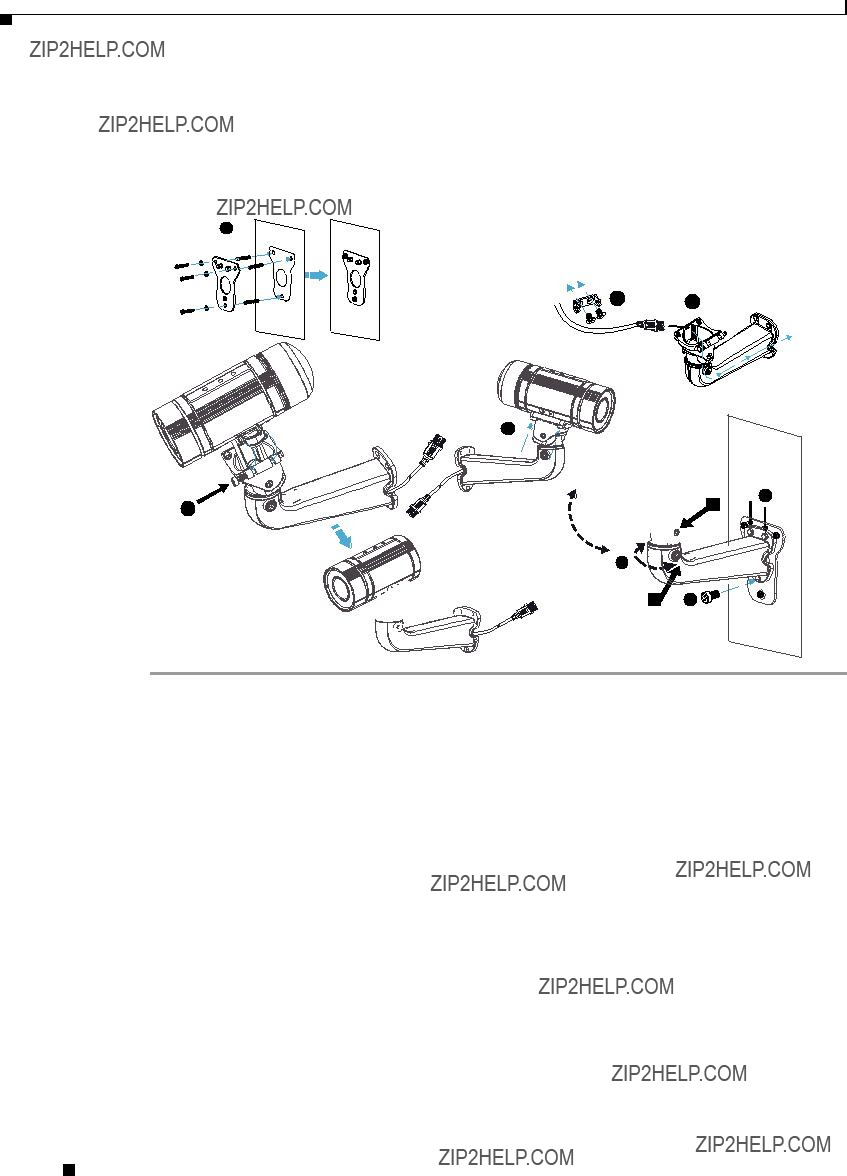
Step 12 (Optional) If the camera is being install in an area of high humidity, remove the back cover from the camera, place the included silica gel packet in the camera, and then replace the back cover onto the camera.
Figure
1
What to do next
After you install the IP camera, follow the instructions in Chapter 3, ???Performing the Initial Setup of the IP Camera??? to access and configure the IP camera.
Cisco Video Surveillance 6400 IP Camera Installation Guide

Chapter 2 Camera Installation
Connecting External Power and I/O Cables
Connecting External Power and I/O Cables
The 6400 IP camera can be powered using Power over Ethernet (PoE), or by using an external power source. If an external power source is used, a power cable must be connected to the General Purpose I/O (GPIO) terminal block on the IP camera. Additionally, external devices that trigger alarms or respond to alarms can be connected to the GPIO terminal block using I/O cables. To avoid moisture damage to the IP camera, the optional external power cable and I/O cables, which are
To connect an external power cable or I/O cables for external devices, perform the following steps:
Procedure
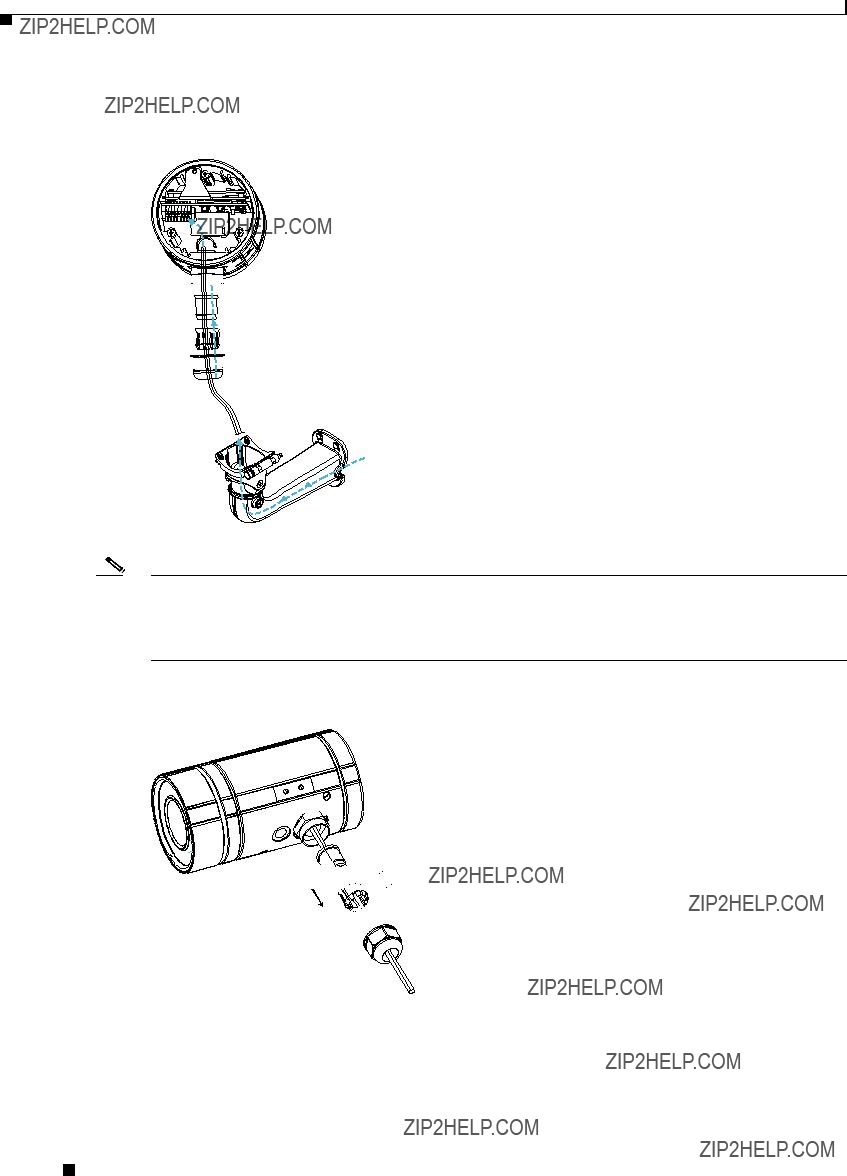
Step 1 Disassemble the components of the waterproof connector into its individual components as shown below.
Screw Nut (A)
Seal (B)
Seals (C)
Housing (D)
 Sealing Nut (E)
Step 2 Remove the back cover from the IP camera.
Step 3 Remove the rubber stopper from the bottom of the IP Camera and tightly secure the screw nut (A).


 (A)
(A)
Cisco Video Surveillance 6400 IP Camera Installation Guide
Chapter 2 Camera Installation
Connecting External Power and I/O Cables
Step 4 Feed the external power cable and I/O cables through the wall mount bracket and the waterproof connector components (E


 (A)
(A)
(B)
(D)


 (E)
(E)
4
Note There are seven holes on the seal (B), and the widest hole with a crack on the side is specific for the power cable.
The recommended I/O cable gauge is 2.0 ~ 2.8 mm.
Step 5 Push the seal (B) into the housing (D), and to avoid moisture, insert the seals (C) into the empty holes on the seal (B).

 (E)
(E)

(B) 


 (C)
(C)
(D) 


Cisco Video Surveillance 6400 IP Camera Installation Guide

Chapter 2 Camera Installation
Connecting External Power and I/O Cables
Step 6 Secure the sealing nut (E) tightly.

 (E)
(E)
Step 7 Connect the external power and I/O cables to the GPIO terminal block. The pin locations and descriptions are as follows:
Step 8 Replace the back cover back onto the camera.
Cisco Video Surveillance 6400 IP Camera Installation Guide
Chapter 2 Camera Installation
Connecting a Waterproof Ethernet Cable
Connecting a Waterproof Ethernet Cable
To connect the 6400 IP camera to an Ethernet cable with a waterproof connection, perform the following steps.
Procedure
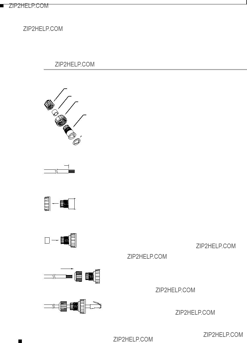
Step 1 Disassemble the components of the waterproof connector into its individual components as shown below.
Sealing Nut (A)
Seal (B)
Screw Nut (C)
Housing (D)
 Gasket (E)
Step 2 Strip about 1/2 inch (12 mm) of the sheath off the end of an Ethernet cable.
 1/2 in. (12 mm)
Step 3 Insert the housing (D) into the screw nut (C).
(C)(D)
Step 4 Insert the seal (B) into the housing (D).
(B)
Step 5 Insert the stripped Ethernet cable through the sealing nut (A) and the housing (D).
(A)
Step 6 Clamp the cable with an RJ45 plug.
Cisco Video Surveillance 6400 IP Camera Installation Guide

Chapter 2 Camera Installation
Installing the Sun Shield
Step 7 Push the RJ45 plug into the housing (D) and tighten the sealing nut.
Step 8 Attach the gasket to the front surface of the housing (D).
(E)
Step 9 Connect the Ethernet cable to the RJ45 jack and tighten the waterproof connector.
Installing the Sun Shield
To install the sun shield, perform the following steps.
Procedure
Step 1 Attach the two included standoff screws to the top of the 6400 IP camera.
Cisco Video Surveillance 6400 IP Camera Installation Guide

Chapter 2 Camera Installation
Installing the Sun Shield
Step 2 Place the sun shield on top of the two standoff screws and slide it backward or forward to the desired position. Ensure that the holes in the top of the standoff screws are visible through the holes in the sun shield.
Step 3 Use the two included screws to secure the sun shield to the two standoff screws.
C H A P T E R 3
Performing the Initial Setup of the IP Camera
After you install IP camera as described in the Chapter 2, ???Camera Installation,??? or after you perform a factory reset procedure, you must access the IP camera and make initial configuration settings. These settings include administrator and root passwords, and whether the IP camera can be accessed through an HTTP connection in addition to the default HTTPS (HTTP secure) connection.
To make these configuration settings, you connect to the IP camera from any PC that is on the same network as the IP camera. The PC must meet these requirements:
???Operating
???
In addition, you must know the IP address and default login credentials of the IP camera. By default, when the IP camera powers on, it attempts to obtain an IP address from a DHCP server in your network. If the camera cannot obtain an IP address through DCHP within 90 seconds, it uses a default IP address of 192.168.0.100. The default login credentials (Username/Password) are admin/admin.
To connect to the IP camera for the first time and make initial configuration settings, perform the following steps. You can change these configuration settings in the future as described in the Cisco Video Surveillance 6000 Series IP Camera Configuration Guide.
Before you Begin
The Microsoft .NET Framework version 2.0 or later must be installed on the PC that you use to connect to the IP camera. You can download the .NET Framework from the Microsoft website.
Procedure
Step 1 Start Internet Explorer, enter HTTPS://ip_address in the address field, and press Enter.
Replace ip_address with the IP address that the IP camera obtained through DHCP or, if the camera was unable to obtain this IP address, enter 192.168.0.100.
The Login window appears.
Step 2 Enter the default login credentials:
Username: admin
Password: admin
The Initialization window appears.
Cisco Video Surveillance 6400 IP Camera Installation Guide

Chapter 3 Performing the Initial Setup of the IP Camera
Step 3 In the Password and Confirm Password fields of the admin row, enter a password for the IP camera administrator.
You must enter the same password in both fields. The password is case sensitive and must contain at least eight characters, which can be letters, numbers, and special characters, but no spaces. Special characters are: ! " # $ % & ' ( ) * + ,
Step 4 In the Password and Confirm Password fields of the Root row, enter a password that is used when accessing the IP camera through a Secure Shell (SSH) connection.
You must enter the same password in both fields. The password is case sensitive and must contain at least eight characters, which can be letters, numbers, and special characters, but no spaces. Special characters are: ! " # $ % & ' ( ) * + ,
You use the root password if you need to troubleshoot the IP camera through a SSH connection with the assistance of the Cisco Technical Assistance Center.
Step 5 In the Access Protocols area, check the Enable HTTP check box if you want to allow both HTTP and HTTPS connections to the IP camera.
By default, only the Enable HTTPS check box is checked, which allows only HTTPS (secure) connections to the IP camera.
Step 6 Click Apply.
The IP camera reboots and the Login window appears.
Step 7 After the IP camera reboots, start Internet Explorer and, in the Address field, enter the following:
protocol://ip_address
where:
???protocol is HTTPS or HTTP. (You can use HTTP only if you enabled it in Step 5.)
???ip_address is the IP address that you used in Step 1.
Step 8 If you are prompted to install ActiveX controls, which are required to view video from the IP camera, follow the
The Home (System Information) window appears.
Cisco Video Surveillance 6400 IP Camera Installation Guide

C H A P T E R 4
Camera Management
This chapter provides information and instructions for managing the Cisco Video Surveillance 2620 IP Camera, and includes the following topics:
???Understanding the IP Camera User Interface, page
???Adjusting the IP Camera Focus and Zoom, page
???Powering the IP Camera On or Off, page
???Resetting the IP Camera, page
???Viewing Live Video, page
Understanding the IP Camera User Interface
After you log in to the IP camera, you can access the IP camera windows and perform a variety of administrative and user procedures.
The links and activities that you can see and access in the IP camera windows depend on your IP camera privilege level.
???
???
IP Camera Window Links
The IP Camera user interface includes links that you use to access various windows and perform other activities. Table
Cisco Video Surveillance 6400 IP Camera Installation Guide

Chapter 4 Camera Management
Understanding the IP Camera User Interface
IP Camera Windows
The IP camera user interface includes these main windows:
???Home
???Setup
???Camera Video & Control
Cisco Video Surveillance 6400 IP Camera Installation Guide

Chapter 4 Camera Management
Understanding the IP Camera User Interface
Cisco Video Surveillance 6400 IP Camera Installation Guide

Chapter 4 Camera Management
Adjusting the IP Camera Focus and Zoom
Adjusting the IP Camera Focus and Zoom
To adjust the IP camera focus and zoom, perform the following steps while viewing video from the camera. For information about viewing video, see ???Viewing Live Video??? section on page
Procedure
Step 1 Login to the IP camera.
The Home window appears.
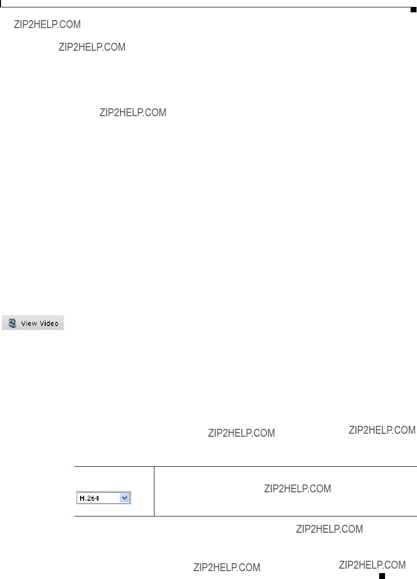
Step 2 Click the View Video link.
The Camera Video & Control window appears.
Step 3 Verify that the field of view is correctly set.
Step 4 Click the Focus/Zoom toggle button located below the video pane.
Step 5 The focus and zoom controls appear.
Step 6 While watching the video pane, perform the following steps:
a.Move the Zoom slider until you achieve the desired zoom level.
b.Move the Focus slider until the video image is at its sharpest.
Step 7 (Optional) Click Auto Focus to have the IP camera automatically adjust its focus. To automatically adjust the focus to a particular region in the field of view, check the Specify Region check box and draw or select a region before clicking Auto Focus.
Powering the IP Camera On or Off
The IP camera does not include an on/off switch. You power it on or off by connecting it to or disconnecting it from a power source. When you power off the IP camera, configuration settings are retained.
To power on the IP camera, take either of these actions:
???Use an STP (shielded twisted pair) Category 5 or higher network cable to connect the IP camera to a network switch that provides 802.3af compliant PoE.
???Use an optional 12 VDC or 24VAC power adapter to connect the IP camera to a wall outlet
To power off the IP camera, take either of these actions:
???If the IP camera is receiving PoE, disconnect the network cable
???If the IP camera is receiving power through the power adapter, unplug the adapter from the wall or disconnect it from the camera
Resetting the IP Camera
You reset the IP camera by pressing the Reset button on the IP Camera (see Figure
Cisco Video Surveillance 6400 IP Camera Installation Guide
Chapter 4 Camera Management
Viewing Live Video
You also can also perform these reset operations from the Maintenance Settings window as described in the Cisco Video Surveillance 6000 Series IP Camera Configuration Guide.
Viewing Live Video
After you install and set up the Cisco Video Surveillance IP Camera, you can connect to the IP camera through Internet Explorer and access the Camera Video & Control window to view live video.
The Camera Video & Control window also provides for controlling the video display, configuring preset positions, and controlling certain IP camera functions. Available controls depend on the privilege level of the user.
To view live video, log in to the IP camera, then click View Video in the IP camera Main window menu bar. The Camera Video & Control window appears. This window displays live video from the camera and lets you control a variety of camera and display functions.
The controls that you see in the Camera Video & Control window depend on your IP camera privilege level and the configurations settings for the IP camera. Users with the Administrator privilege can access all controls. Users with the Viewer privilege do not have access to the following controls:
???Video image controls
???Motion detection controls
Table
Table
Video controls
Video Codec
Choose the codec for video transmission (H.264 or MJPEG).
You can choose H.264 only if the primary video stream (channel 1) is enabled. You can choose MJPEG only if the secondary video stream (channel 2) is enabled.
Cisco Video Surveillance 6400 IP Camera Installation Guide

Chapter 4 Camera Management
Viewing Live Video
Table
Video image controls
Note These controls appear when you click the Right Arrow in the Video Control area.
Cisco Video Surveillance 6400 IP Camera Installation Guide

Chapter 4 Camera Management
Viewing Live Video
Motion detection
Up Arrow toggle button
Down Arrow toggle button
Click the Up Arrow to display the motion detection controls. The button changes to the Down Arrow button.
Click the Down Arrow button to hide the motion detection controls. The button changes to the Up Arrow button.
Cisco Video Surveillance 6400 IP Camera Installation Guide

Chapter 4 Camera Management
Viewing Live Video
Table
Motion detection controls
Note These controls appear when you click the Up Arrow in the Motion Detection area and are available only viewing the primary (H.264) stream.
Cisco Video Surveillance 6400 IP Camera Installation Guide
Chapter 4 Camera Management
Viewing Live Video
Table
Cisco Video Surveillance 6400 IP Camera Installation Guide

Chapter 4 Camera Management
Viewing Live Video