Cisco Model DPC3825 and EPC3825
8x4 DOCSIS 3.0 Wireless
Residential Gateway User Guide
In This Document
???
???
???
???
???
???
???
???
???
???
???
???
???
???
???
???
???
???
???
???
???
Cisco Model DPC3825 and EPC3825
8x4 DOCSIS 3.0 Wireless
Residential Gateway User Guide
In This Document
???
???
???
???
???
???
???
???
???
???
???
???
???
???
???
???
???
???
???
???
???

IMPORTANT SAFETY INSTRUCTIONS
IMPORTANT SAFETY INSTRUCTIONS
Notice to Installers
The servicing instructions in this notice are for use by qualified service personnel only. To reduce the risk of electric shock, do not perform any servicing other than that contained in the operating instructions, unless you are qualified to do so.
Notice ?? l???attention des installateurs de r??seaux c??bl??s
Les instructions relatives aux interventions d???entretien, fournies dans la pr??sente notice, s???adressent exclusivement au personnel technique qualifi??. Pour r??duire les risques de chocs ??lectriques, n???effectuer aucune intervention autre que celles d??crites dans le mode d'emploi et les instructions relatives au fonctionnement, ?? moins que vous ne soyez qualifi?? pour ce faire.

IMPORTANT SAFETY INSTRUCTIONS
Mitteilung f??r
Die in dieser Mitteilung aufgef??hrten Wartungsanweisungen sind ausschlie??lich f??r qualifiziertes Fachpersonal bestimmt. Um die Gefahr eines elektrischen Schlags zu reduzieren, sollten Sie keine Wartungsarbeiten durchf??hren, die nicht ausdr??cklich in der Bedienungsanleitung aufgef??hrt sind, au??er Sie sind zur Durchf??hrung solcher Arbeiten qualifiziert.
Aviso a los instaladores de sistemas CATV
Las instrucciones de reparaci??n contenidas en el presente aviso son para uso exclusivo por parte de personal de mantenimiento cualificado. Con el fin de reducir el riesgo de descarga el??ctrica, no realice ninguna otra operaci??n de reparaci??n distinta a las contenidas en las instrucciones de funcionamiento, a menos que posea la cualificaci??n necesaria para hacerlo.
20080814_Installer820_Intl

IMPORTANT SAFETY INSTRUCTIONS
IMPORTANT SAFETY INSTRUCTIONS
1)Read these instructions.
2)Keep these instructions.
3)Heed all warnings.
4)Follow all instructions.
5)Do not use this apparatus near water.
6)Clean only with dry cloth.
7)Do not block any ventilation openings. Install in accordance with the manufacturer's instructions.
8)Do not install near any heat sources such as radiators, heat registers, stoves, or other apparatus (including amplifiers) that produce heat.
9)Do not defeat the safety purpose of the polarized or
10)Protect the power cord from being walked on or pinched particularly at plugs, convenience receptacles, and the point where they exit from the apparatus.
11)Only use attachments/accessories specified by the manufacturer.
12)Use only with the cart, stand, tripod, bracket, or table specified by the manufacturer, or sold with the apparatus. When a cart is used, use caution when moving the cart/apparatus combination to avoid injury from
13)Unplug this apparatus during lightning storms or when unused for long periods of time.
14)Refer all servicing to qualified service personnel. Servicing is required when the apparatus has been damaged in any way, such as a
Power Source Warning
A label on this product indicates the correct power source for this product. Operate this product only from an electrical outlet with the voltage and frequency indicated on the product label. If you are uncertain of the type of power supply to your home or business, consult your service provider or your local power company.
The AC inlet on the unit must remain accessible and operable at all times.
Ground the Product
WARNING: Avoid electric shock and fire hazard! If this product connects to coaxial cable wiring, be sure the cable system is grounded (earthed). Grounding provides some  protection against voltage surges and

IMPORTANT SAFETY INSTRUCTIONS
Protect the Product from Lightning
In addition to disconnecting the AC power from the wall outlet, disconnect the signal inputs.
Verify the Power Source from the On/Off Power Light
When the on/off power light is not illuminated, the apparatus may still be connected to the power source. The light may go out when the apparatus is turned off, regardless of whether it is still plugged into an AC power source.
Eliminate AC Mains Overloads
WARNING: Avoid electric shock and fire hazard! Do not overload AC mains, outlets, extension cords, or integral convenience receptacles. For products that require battery power or other power sources to operate them, refer to the operating instructions for those products.
Provide Ventilation and Select a Location
???Remove all packaging material before applying power to the product.
???Do not place this apparatus on a bed, sofa, rug, or similar surface.
???Do not place this apparatus on an unstable surface.
???Do not install this apparatus in an enclosure, such as a bookcase or rack, unless the installation provides proper ventilation.
???Do not place entertainment devices (such as VCRs or DVDs), lamps, books, vases with liquids, or other objects on top of this product.
???Do not block ventilation openings.
Protect from Exposure to Moisture and Foreign Objects
WARNING: Avoid electric shock and fire hazard! Do not expose this product to dripping or splashing liquids, rain, or moisture. Objects filled with liquids, such as  vases, should not be placed on this apparatus.
WARNING: Avoid electric shock and fire hazard! Unplug this product before cleaning. Do not use a liquid cleaner or an aerosol cleaner. Do not use a magnetic/static cleaning  device (dust remover) to clean this product.
WARNING: Avoid electric shock and fire hazard! Never push objects through the openings in this product. Foreign objects can cause electrical shorts that can result in  electric shock or fire.
Service Warnings
WARNING: Avoid electric shock! Do not open the cover of this product. Opening or removing the cover may expose you to dangerous voltages. If you open the cover, your  warranty will be void. This product contains no
IMPORTANT SAFETY INSTRUCTIONS
Check Product Safety
Upon completion of any service or repairs to this product, the service technician must perform safety checks to determine that this product is in proper operating condition.
Protect the Product When Moving It
Always disconnect the power source when moving the apparatus or connecting or disconnecting cables.
20090915_Modem No Battery_Safety

IMPORTANT SAFETY INSTRUCTIONS
United States FCC Compliance
This device has been tested and found to comply with the limits for a Class B digital device, pursuant to part 15 of the FCC Rules. These limits are designed to provide reasonable protection against such interference in a residential installation. This equipment generates, uses, and can radiate radio frequency energy. If not installed and used in accordance with the instructions, it may cause harmful interference to radio communications. However, there is no guarantee that interference will not occur in a particular installation. If this equipment does cause harmful interference to radio or television reception, which can be determined by turning the equipment OFF and ON, the user is encouraged to try to correct the interference by one or more of the following measures:
???Reorient or relocate the receiving antenna.
???Increase the separation between the equipment and receiver.
???Connect the equipment into an outlet on a circuit different from that to which the receiver is connected.
???Consult the service provider or an experienced radio/television technician for help.
Any changes or modifications not expressly approved by Cisco Systems, Inc., could void the user's authority to operate the equipment.
The information shown in the FCC Declaration of Conformity paragraph below is a requirement of the FCC and is intended to supply you with information regarding the FCC approval of this device. The phone numbers listed are for
Declaration of Conformity
Canada EMI Regulation
This Class B digital apparatus complies with Canadian
Cet appareil num??rique de la class B est conforme ?? la norme
IMPORTANT SAFETY INSTRUCTIONS
Dynamic Frequency Selection (DFS) Dual Band Frequencies
Some configurations of this product may operate in the
restricted to indoor operation only per FCC guidance. The use of this product on the affected frequencies when outside is in
Radiation Exposure Statements
Note: This transmitter must not be
US
This system has been evaluated for RF exposure for humans in reference to ANSI C 95.1 (American National Standards Institute) limits. The evaluation was based in accordance with FCC OET Bulletin 65C rev 01.01 in compliance with Part 2.1091 and Part 15.27. The minimum separation distance from the antenna to general bystander is 7.9 inches (20 cm) to maintain compliance.
Canada
This system has been evaluated for RF exposure for humans in reference to ANSI C 95.1 limits. The evaluation was based on evaluation per
EU
This system has been evaluated for RF exposure for humans in reference to the ICNIRP (International Commission on
Australia
This system has been evaluated for RF exposure for humans as referenced in the Australian Radiation Protection standard and has been evaluated to the ICNIRP (International Commission on
20091016 FCC DSL_Dom and Intl

IMPORTANT SAFETY INSTRUCTIONS
CE Compliance
Declaration of Conformity with Regard to the EU Directive 1999/5/EC (R&TTE Directive)
This declaration is only valid for configurations (combinations of software, firmware and hardware) supported or provided by Cisco Systems for use within the EU. The use of software or firmware not supported or provided by Cisco Systems may result in the equipment no longer being compliant with the regulatory requirements.

IMPORTANT SAFETY INSTRUCTIONS
Note: The full declaration of conformity for this product can be found in the Declarations of Conformity and Regulatory Information section of the appropriate product hardware installation guide, which is available on Cisco.com.
The following standards were applied during the assessment of the product against the requirements of the Directive 1999/5/EC:
???
???
???
Radio: EN 300 328
EMC: EN 301
Safety: EN 60950 and EN 50385
The CE mark and
National Restrictions
This product is for indoor use only.
France
For 2.4 GHz, the output power is restricted to 10 mW EIRP when the product is used outdoors in the band 2454 - 2483,5 MHz. There are no restrictions when used in other parts of the 2,4 GHz band. Check http://www.arcep.fr/ for more details.
Pour la bande 2,4 GHz, la puissance est limit??e ?? 10 mW en p.i.r.e. pour les ??quipements utilis??s en ext??rieur dans la bande 2454 - 2483,5 MHz. Il n'y a pas de restrictions pour des utilisations dans d'autres parties de la bande 2,4 GHz. Consultez http://www.arcep.fr/ pour de plus amples d??tails.
Italy
This product meets the National Radio Interface and the requirements specified in the National Frequency Allocation Table for Italy. Unless this wireless LAN product is operating within the boundaries of the owner's property, its use requires a ???general authorization.???
Please check http://www.comunicazioni.it/it/ for more details.
Questo prodotto ?? conforme alla specifiche di Interfaccia Radio Nazionali e rispetta il Piano Nazionale di ripartizione delle frequenze in Italia. Se non viene installato all 'interno del proprio fondo, l'utilizzo di prodotti Wireless LAN richiede una ???Autorizzazione Generale???.
Consultare http://www.comunicazioni.it/it/ per maggiori dettagli.
IMPORTANT SAFETY INSTRUCTIONS
Latvia
The outdoor usage of the 2.4 GHz band requires an authorization from the Electronic Communications Office. Please check http://www.esd.lv for more details.
2,4 GHz frekven??u joslas izmanto??anai ??rpus telp??m nepiecie??ama at??auja no Elektronisko sakaru direkcijas. Vair??k inform??cijas: http://www.esd.lv.
Note: The regulatory limits for maximum output power are specified in EIRP. The EIRP level of a device can be calculated by adding the gain of the antenna used (specified in dBi) to the output power available at the connector (specified in dBm).
Antennas
Use only the antenna supplied with the product.
20090312 CE_Gateway
Introduction
Introduction
Welcome to the exciting world of
This guide provides procedures and recommendations for placing, installing, configuring, operating, and troubleshooting your DPC3825 and EPC3825 residential gateway for
Benefits and Features
Your new DPC3825 and EPC3825 residential gateway offers the following outstanding benefits and features:
???Compliant with DOCSIS 3.0, 2.0, and 1.x standards along with PacketCable??? and EuroPacketCable??? specifications to deliver
???High performance broadband Internet connectivity to energize your online experience
???Four
???802.11n Wireless Access Point
???Wireless Protected Setup (WPS), including a push button switch to activate WPS for simplified and secure wireless setup
???User configurable Parental Control blocks access to undesirable Internet sites
???Advanced firewall technology deters hackers and protects the home network from unauthorized access
???Attractive compact design that allows for vertical, horizontal, or
Introduction
???
???
???Allows automatic software upgrades by your service provider

What's In the Carton?
What's In the Carton?
When you receive your wireless residential gateway, you should check the equipment and accessories to verify that each item is in the carton and that each item is undamaged. The carton contains the following items:
One of the DOCSIS Residential Gateway models (DPC3825 or EPC3825)
One Ethernet cable
One
OR
One
One
If any of these items are missing or damaged, please contact your service provider for assistance.
Note: You will need an optional cable signal splitter and additional standard RF coaxial cables if you want to connect a VCR, a Digital Home Communications Terminal (DHCT) or a

Front Panel Description
Front Panel Description
The front panel of your residential gateway provides LED status indicators that indicate how well and at what state your residential gateway is operating. See Front Panel LED Status Indicator Functions (on page 96), for more information on front panel LED status indicator functions.
Model DPC3825 shown here
1
2
3
4
5ETHERNET 1 -
6
7WIRELESS
8WIRELESS

Back Panel Description
Back Panel Description
The following illustrations show the description and function of the back panel components on the Cisco DPC3825 residential gateway.
1

 CAUTION:
Avoid damage to your equipment. Only use the power supply that is provided with your residential gateway.
2ON/OFF SWITCH (European models
3MAC ADDRESS
4
5
6
7WIRELESS

Back Panel Description
8

 CAUTION:
The Reset button is for maintenance purposes only. Do not use unless instructed to do so by your cable service provider. Doing so may cause you to lose any cable modem settings you have selected.
What Are the System Requirements for Internet Service?
What Are the System Requirements for Internet Service?
To ensure that your residential gateway operates efficiently for
Note: You will also need an active cable input line and an Internet connection.
Minimum System Requirements for a PC
???A PC with a Pentium MMX 133 processor or greater
???32 MB of RAM
???Web browsing software
???
Minimum System Requirements for Macintosh
???MAC OS 7.5 or later
???32 MB of RAM
System Requirements for an Ethernet Connection
???A PC with Microsoft Windows 2000 operating system (or later) with TCP/IP protocol installed, or an Apple Macintosh computer with TCP/IP protocol installed
???An active

How Do I Subscribe to
How Do I Subscribe to
Before you can use your residential gateway, you need to have a
I Do Not Have a
If you do not have a
You will need to give your service provider the following information:
???The serial number of the modem
???The Media Access Control (MAC) address of the modem (CM MAC)
???Other MAC address numbers as needed
These numbers appear on a bar code label located on the residential gateway. The serial number consists of a series of alphanumeric characters preceded by S/N. The MAC address consists of a series of alphanumeric characters preceded by CM MAC. The following illustration shows a sample bar code label.
Write down these numbers in the space provided here.
Serial Number _______________________
MAC Address ________________________
I Already Have an Existing
If you have an existing
Where Is the Best Location for My DOCSIS Residential Gateway?
Where Is the Best Location for My DOCSIS Residential Gateway?
The ideal location for your residential gateway is where it has access to outlets and other devices. Think about the layout of your home or office, and consult with your service provider to select the best location for your residential gateway. Read this user guide thoroughly before you decide where to place your residential gateway.
Consider these recommendations:
???Choose a location close to your computer if you will also use the residential gateway for
???Choose a location that is near an existing RF coaxial connection to eliminate the need for an additional RF coaxial outlet.
???Choose a location that is relatively protected from accidental disturbance or harm, such as a closet, basement, or other protected area.
???Choose a location so that there is plenty of room to guide the cables away from the modem without straining or crimping them.
???Airflow around the residential gateway should not be restricted.
???Read this user guide thoroughly before installing the residential gateway.
How Do I Mount the Modem on a Wall? (Optional)
How Do I Mount the Modem on a Wall? (Optional)
You can mount the residential gateway on a wall using two wall anchors, two screws, and the mounting slots located on the unit. The modem can be mounted vertically or horizontally.
Before You Begin
Before you begin, choose an appropriate mounting place. The wall can be made of cement, wood, or drywall. The mounting location should be free of obstructions on all sides, and the cables should be able to easily reach the residential gateway without strain. Leave sufficient clearance between the bottom of the residential gateway and any flooring or shelving underneath to allow access to cabling. In addition, leave enough slack in all cables so that the residential gateway can be removed for any required maintenance without disconnecting the cables. Also, verify that you have the following items:
???Two wall anchors for #8 x
???Two #8 x
???Drill with a
???A copy of the

How Do I Mount the Modem on a Wall? (Optional)
Location and Dimensions of the
The following illustration shows the location and dimensions of the
How Do I Mount the Modem on a Wall? (Optional)
Mounting the Residential Gateway on a Wall
1 Using a drill with a
Note: The preceding graphic illustrates the location of the mounting holes on the back of the residential gateway.
2Are you mounting the residential gateway into a drywall or concrete surface where a wooden stud is available?
???If yes, go to step 3.
???If no, drive the anchor bolts into the wall, and install the mounting screws into the anchor bolts; leave a gap of about
3Install the mounting screws into the wall; leave a gap of about
4Verify that no cables or wires are connected to the residential gateway.
5Lift the residential gateway into position. Slip the large end of both mounting slots (located in the back of the residential gateway) over the mounting screws, and then slide the residential gateway down until the narrow end of the keyhole slot contacts the screw shaft.
Important: Verify that the mounting screws securely support the residential gateway before you release the unit.

How Do I Connect My Gateway for Internet Service?
How Do I Connect My Gateway for Internet Service?
You can use your residential gateway to provide Internet access, and you can share that Internet connection with other Internet devices in your home or office. Sharing one connection among many devices is called networking.
Connecting and Installing Internet Devices
Professional installation may be available. Contact your local service provider for further assistance.
To connect devices
The following diagram illustrates one of the various networking options that are available to you.
Connecting the Residential Gateway for
The following installation procedure ensures proper setup and configuration for the residential gateway.
1 Choose an appropriate and safe location to install the residential gateway (close to a power source, an active cable connection, your
WARNING:
???To avoid personal injury, follow the installation instructions in the exact order shown.
???Wiring and connections must be properly insulated to prevent electrical shock.
???Disconnect power from the residential gateway before attempting to connect to any device.
2 Power off your PC and other networking device; then, unplug them from the power source.
How Do I Connect My Gateway for Internet Service?
3 Connect the active RF coaxial cable from your service provider to the coax connector labeled CABLE on the back of the residential gateway.
Note: To connect a TV, DHCT,
4Connect your PC to the residential gateway using either of the following methods.
???Ethernet Connection: Locate the yellow Ethernet cable, connect one end of the Ethernet cable to the Ethernet port on your PC, and connect the other end to the yellow ETHERNET port on the back of the residential gateway.
Note: To install more Ethernet devices than ports provided on the residential gateway, use an external
???Wireless: Make sure that your wireless device is powered up. You will need to associate your wireless device with the wireless gateway once the gateway is operational. Follow the directions provided with your wireless device for associating with a wireless access point.
More information about the factory default configuration of your wireless gateway can be found later in this user guide in Configure Wireless Settings (on page 35).
5Locate the AC power cord provided with your residential gateway. Insert one end of the power cord into the AC connector on the back of the residential gateway. Then, plug the AC power cord into an AC outlet to
6Plug in and power on your PC and other home network devices. The LINK LED on the residential gateway corresponding to the connected devices should be on or blinking.
7Once the residential gateway is online, most Internet devices will have immediate Internet access.
Note: If your PC does not have Internet access, refer to Frequently Asked Questions (on page 91) for information on how to configure your PC for TCP/IP. For Internet devices other than PCs, refer to the DHCP or IP Address configuration section of the User Guide or Operations Manual for those devices.
How Do I Configure My DOCSIS Residential Gateway?
How Do I Configure My DOCSIS Residential Gateway?
To configure your residential gateway, you must first access the WebWizard configuration pages. This section provides detailed instructions and procedures for accessing the WebWizard pages and for configuring your residential gateway to operate correctly. This section also presents examples and descriptions of each WebWizard configuration page. Use the WebWizard pages to customize your residential gateway to your needs rather than using the default settings. The WebWizard pages in this section are organized in the order shown on the Setup page.
Important: The WebWizard pages and the examples shown in this section are for illustration purposes only. Your pages may differ from the pages shown in this guide. The pages shown in this guide also represent the default values for the device.
Note: If you are not familiar with the network configuration procedures detailed in this section, contact your service provider before you attempt to change any of the residential gateway default settings.
Logging in to the Gateway for the First Time
The default configuration of the gateway uses IP address 192.168.0.1. If you have connected the gateway correctly and you have properly configured your computer, use the following steps to log in to the gateway as an administrator.
1 On your PC, open the web browser that you prefer to use.

How Do I Configure My DOCSIS Residential Gateway?
2 In the address field, enter the following IP address: 192.168.0.1. A Status DOCSIS WAN login page similar to the following page opens.
3 On the Status DOCSIS WAN page, leave the User Name and Password field blank and click Log In. The gateway opens with an Administration Management page in the forefront. You can use the Administration Management page to set your User Name and Password.
Important: We highly recommend that you set up a new password to safeguard against the possibility of Internet attacks that look for devices operating with

How Do I Configure My DOCSIS Residential Gateway?
4 On the Administration Management page, create a User Name and Password and then click Save Settings. Once you save the settings for your User Name and Password on the Administration Management page, the Setup Quick Setup page opens.
Important: You have the option to leave the password field blank (factory default). However, if you do not change your User Name and Password, you will be directed to the Administrative Management page each time you access the gateway. This serves as a reminder to set up your personalized password.
Once you have personalized your Password, subsequent logins will take you directly to the Setup Quick Setup page.
5 After you make your selections, click Save Settings to apply your changes or
Cancel Changes to cancel.
Setup > Quick Setup
The Setup Quick Setup page is the first page to open after you have logged on to your gateway. You can use the settings on this page to change your password and to configure the WLAN.
Important: The settings on this page are unique to your device. If you choose, you do not need to make any changes to the settings on this page. These default settings are all that you need to operate a secure wireless network.

How Do I Configure My DOCSIS Residential Gateway?
Configuring Quick Settings
Use the descriptions and instructions in the following table to configure the network settings for the device. After you make your selections, click Save Settings to apply your changes or click Cancel Changes to cancel.

How Do I Configure My DOCSIS Residential Gateway?
???
???
Enable
Disable
Wireless Network Name (SSID)
Allows you to enter a name for your wireless network or to use the default value. The value you enter he will be viewable on PCs and other wireless client devices such as the wireless network name.
Note: The factory default Service Set Identifier (SSID) is either the last 6 characters of the CM MAC Address or the SSID as identified on the product label.
Some service providers supply a special wireless configuration card that provides the SSID information and wireless security information.
Wireless Security Mode
Allows you to select a wireless security mode to help protect your network. If you select Disable then your wireless network is not secure and any wireless device within range may connect to it. See Wireless Security (on page 39) for detailed descriptions of wireless security modes.
Note: The factory default Wireless Security Mode is WPA or
Encryption
Allows you to select a level of encryption based on the wireless security mode you choose. See Wireless Security (on page 39) for detailed descriptions of encryption.
The
Note: Your service provider may provide you with a wireless configuration card that contains SSID and wireless security configuration information for your home network that may differ from what is described above.
How Do I Configure My DOCSIS Residential Gateway?
Setup > Lan Setup
The Setup Lan Setup page allows you to configure the settings for the Local Area Network (LAN) in your home. These settings include the range of IP addresses that define the LAN itself as well as how the addresses are assigned (automatically by DHCP or manually) as new devices are added to the network.
Important: Unless you are knowledgeable about administering IP addresses, we recommend that you do not change these settings. If you change these values incorrectly, you can lose Internet access.
Select the Lan Setup tab to open the Setup Lan Setup page.
Configuring Your Network Settings
Use the descriptions and instructions in the following table to configure the network settings for your residential gateway. After you make your selections, click Save Settings to apply your changes or click Cancel Changes to cancel.

How Do I Configure My DOCSIS Residential Gateway?
???
Click
Notes:
???The Add Static IP button adds the Static IP address to the list of
???The Remove Static IP button removes the Static IP address from the list of
Starting IP Address
Displays the starting address used by the
Setup > DDNS
Dynamic Domain Name Service (DDNS) provides the residential gateway (that may have a changing IP address) with a host name or URL resolvable by network applications through standard DNS queries. DDNS is useful when you are hosting your own website, FTP server, or other server behind the device. Before using this feature, you need to sign up for DDNS service.
Select the DDNS tab to open the Setup DDNS page.

How Do I Configure My DOCSIS Residential Gateway?
Enabling DDNS
Note: In order to use the DDNS feature, you must first set up an account and establish a URL with www.DynDNS.org. The DDNS feature will not work without a valid account.
To set up a DDNS account, open your browser and enter www.DynDNS.org in the address bar. Follow the instructions on the website to set up an account.
To enable DDNS, follow these steps.
1 On the DDNS page, select www.DynDNS.org as your DDNS server.
2 Configure the following fields:
???
???
???
User Name
Password
Host Name
3Click Save Settings. The device will now advise the DDNS service of your current WAN (Internet) IP address whenever this address changes.
Important: The Status area of the window will display the status of the DDNS service connection.
Configure Wireless Settings
Configure Wireless Settings
This section describes the options available from the Wireless pages that you can use to configure the parameters of the WAP to meet your specific requirements and needs.
Wireless > Basic Settings
Setting up your residential gateway for wireless communication provides you with the freedom to connect to the Internet from any location within range of the WAP without having to use wired connections. Select the Basic Settings tab to open the Wireless Basic Settings page.
The Wireless Basic Settings page allows you to choose your wireless network mode and other basic features.
???Wireless Network: Enable or Disable
???Wireless Configuration: Manual or
???Network Mode
???Radio Band
???Channel Width
???Standard Channel
???Wireless Network Name (SSID)
When you select
Important: When using WPS mode, WEP is not supported. If you must use WEP encryption, WPS must be disabled by setting the Wireless Configuration to Manual.
Note: WPS is the default setting.

Configure Wireless Settings
Wireless Configuration
Wireless Configuration
Use the descriptions and instructions in the following table to configure the basic settings for

Wireless Configuration Manual Page Example
Wireless Basic Settings Page Description
Use the following table to configure the basic settings for wireless communication for the residential gateway. After you make your selections, click Save Settings to apply your changes or Cancel Changes to cancel.
Wireless > Wireless Security
Selecting a wireless security mode helps protect your network. If you select Disable, then your wireless network is not secure and any wireless device within range may connect to it.
To keep intruders out of your wireless network, use the Wireless Security page to configure your security parameters including the security mode (the level of encryption), encryption keys, and other security settings.
Select the Wireless Security tab to open the Wireless Security page. The following table shows examples of the Wireless Security page with various wireless security modes selected.

Configure Wireless Settings
Field Descriptions
???Encryption. Select a level of WEP encryption, 40 / 64 bits (10 hex digits) or 104 / 128 bits (26 hex digits).
???Wireless Passphrase. To complete your wireless security setup, you should choose a wireless passphrase that is easy for you to remember and hard for anyone else to guess. The first time you connect a new wireless device to this network you may need to enter this passphrase into the appropriate setup section in the connected device. To improve your network security, do not give out this passphrase to unauthorized uses. Please enter a phrase of letters and/or numbers from 4 to 24 digits long. Then, click Generate to create the Passphrase.
???Key
???TX Key. Choose a Transmit (TX) Key from 1 to 4. The TX key is the key that will be used to encrypt your data. Although four keys can be created, only one key is used for encrypting data. Select one of the four keys for WEP encryption. Use the selected TX key to set up your wireless clients.
Field Descriptions
???Encryption. The default is TKIP+AES.
???
???Key Renewal. Enter a Key Renewal period, which instructs the device how often it should change encryption keys. The default is 3600 seconds.

Configure Wireless Settings
??? WPA or
Field Descriptions
???Encryption. The default is TKIP+AES.
???RADIUS Server. Enter the RADIUS server's IP address.
???RADIUS Port. Enter the port number used by the RADIUS server. The default is 1812.
???Shared Key. Enter the key used by the device and RADIUS server.
???Key Renewal. Enter a Key Renewal period, which instructs the device how often it should change encryption keys. The default is 3600 seconds.

Configure Wireless Settings
Wireless > MAC Filter
The MAC Filter feature is used to either allow or block access to your wireless LAN based on the MAC Address of the wireless client devices. The MAC Filter feature, also known as an access list, can be used to help protect your wireless network from access by unauthorized users.
Select the MAC Filter tab to open the Wireless MAC Filter page.
Wireless MAC Filter Page Description
Use the descriptions and instructions in the following table to configure the MAC address filtering for the wireless network for your residential gateway. After you make your selections, click Save Settings to apply your changes or Cancel Changes to cancel.

MAC Address
Filter List
MAC Address Filter List
The MAC Address Filter List displays users whose wireless access you want to control. Click Wireless Client List to display a list of network users by MAC address. From the To Sort by
Wireless > Advanced Settings
Your advanced wireless settings add another layer of security to the wireless network for your residential gateway. This page is used to set up the advanced wireless functions. Only an expert administrator should adjust these settings. Incorrect settings can reduce wireless performance.
Select the Advanced Settings tab to open the Wireless Advanced Settings page.
Use this page to configure the following options:
???N Transmission Rate
???CTS Protection Mode
???Beacon Interval
???DTM Interval
???Fragmentation Threshold
???RTS Threshold

Configure Wireless Settings
Wireless Advanced Settings Page Description
Use the descriptions and instructions in the following table to configure the advanced wireless settings for your residential gateway. After you make your selections, click Save Settings to apply your changes or Cancel Changes to cancel.

Configure Wireless Settings
???
???
???
???
???
???
???
???
???
???
???
???
???
???
???
???
???
???
Auto (factory default)
Use Legacy Rate
0:6.5 or 13.5 Mbps
1:13 or 27 Mbps
2:19.5 or 40.5 Mbps
3:26 or 54 Mbps
4:39 or 81 Mbps
5:52 or 108 Mbps
6:58.5 or 121.5 Mbps
7:65 or 135 Mbps
8:13 or 27 Mbps
9:26 or 54 Mbps
10:39 or 81 Mbps
11:52 or 108 Mbps
12:78 or 162 Mbps
13:104 or 216 Mbps 14:117 or 243 Mbps
15:130 or 270 Mbps
CTS Protection Mode
CTS
Beacon Interval
The Beacon Interval value indicates the frequency interval of the beacon. A beacon is a packet broadcast by the device to synchronize the wireless network.
(Default: 100 msec, Range:

Configure Wireless Settings
Wireless > WDS Settings
The Wireless Distribution System (WDS) Settings page allows you to expand the coverage of your wireless network by deploying signal repeaters. Make sure the channel settings are the same for all WDS enabled devices.
Select the WDS Settings tab to open the Wireless WDS Settings page. Use this page to configure the WDS settings.
Wireless WDS Settings Page Description
Use the descriptions and instructions in the following table to configure the wireless distribution system settings for your residential gateway. After you make your selections, click Save Settings to apply your changes or Cancel Changes to cancel.

Configure Wireless Settings
Wireless > QoS
Quality of Service (QoS) ensures better service to
Wireless QoS Page Description
Use the descriptions and instructions in the following table to configure each QoS setting. After you make your selections, click Save Settings to apply your changes or
Cancel Changes to cancel.
???
???
Enable (factory default)
Disable
Configure Security
Configure Security
Security > Firewall
Advanced firewall technology deters hackers and protects the home network from unauthorized access. Use this page to configure a firewall that can filter out various types of unwanted traffic on the gateway???s local network.
Select the Firewall tab to open the Security Firewall page.
Use the descriptions and instructions in the following table to configure the firewall for your residential gateway. After you make your selections, click Save Settings to apply your changes or Cancel Changes to cancel.
???
???
Enable (factory default)
Disable
Block
Enables/disables popup windows. Some commonly used applications employ popup windows as part of the application. If you disable popup windows, it may interfere with some of these applications.
Block Web Page Cookies
Enables/disables cookie blocking. This feature filters the unsolicited delivery of cookies to devices from the Internet to devices in your private local network. Cookies are computer files that contain personal information or web surfing behavior data.

Configure Security
Security > VPN Passthrough
Use this page to configure Virtual Private Network (VPN) support. Enabling the settings on this page allows VPN tunnels using IPsec or PPTP protocols to pass through the gateway's firewall. Select the VPN Passthrough tab to open the Security VPN Passthrough page.
Use the descriptions and instructions in the following table to configure the VPN passthrough for your residential gateway. After you make your selections, click Save Settings to apply your changes or Cancel Changes to cancel.
???
???
Enable (factory default)
Disable
PPTP Passthrough
Enables/disables
Select the desired option:
???
???
Enable (factory default)
Disable
Configure Security
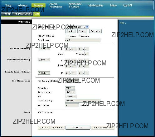
Security > VPN
A Virtual Private Network (VPN) is a connection between two endpoints in different networks that allows private data to be sent securely over public networks or other private networks. This is accomplished by creating a "VPN tunnel." A VPN tunnel connects the two PCs or networks and allows data to be transmitted over the Internet as if it were on a private network. The VPN tunnel uses IPsec to encrypt the data sent between the two endpoints and encapsulate the data within a normal Ethernet/IP frame allowing the data to pass between networks securely and seamlessly.
A VPN provides a
For example, a VPN allows users to sit at home and connect to his/her employer's corporate network and receive an IP address in their private network just as though they were sitting in their office connected to their corporate LAN.
Select the VPN tab to open the Security VPN page.
Use this page to configure the VPN for your residential gateway.
Configure Security
Security VPN Tunnel Page Description
Use the descriptions and instructions in the following table to configure the VPN tunnel for your gateway. After you make your selections, click Save Settings to apply your changes or Cancel Changes to cancel.

Key
Management
Key Exchange Method
The gateway supports both automatic and manual key management. When automatic key management is selected, Internet Key Exchange (IKE) protocols are used to negotiate key material for Security Association (SA). If manual key management is selected, no key negotiation is needed. Basically, manual key management is used in small static environments or for troubleshooting purposes. Note that both sides must use the same key management method.

Configure Security
View Log
The Security VPN View Log page shows events captured by the firewall. The log displays the following items:
???Description of the event
???Number of events that have occurred
???Last occurrence of an event
???Target and source addresses
You can view the following logs from this page:
???Access log
???Firewall log
???VPN log
???Parental Control log
Click Clear to clear the log data.

Control Access to the Gateway
Control Access to the Gateway
Access Restrictions > IP Address Filtering
Use the Access Restrictions IP Filtering page to configure IP address filters. These filters block a range of IP addresses from accessing the Internet.
Note: If you are not familiar with the advanced settings detailed in this section, contact your service provider before you attempt to change any of the residential gateway default advanced IP filtering settings.
Select the IP Address Filtering tab to open the Access Restrictions IP Address Filtering page. After you make your selections, click Save Settings to apply your changes or Cancel Changes to cancel.
Access Restrictions > MAC Address Filtering
Use the Access Restrictions MAC Address Filtering page to configure MAC address filters. These filters permit you to allow or block a range of MAC addresses from accessing the Internet based on MAC Address.
Note: If you are not familiar with the advanced settings detailed in this section, contact your service provider before you attempt to change any of the residential gateway default advanced IP filtering settings.
Control Access to the Gateway
Select the MAC Address Filtering tab to open the Access Restrictions MAC Address Filtering page.
The Block/Pass drop down menu allows you to block or pass Internet access to the MAC addresses of the devices you list in the MAC Address Filters table. The following table describes the function of the Block/Pass drop down menu. After you make your selections, click Save Settings to apply your changes or Cancel Changes to cancel.
Function Keys
The following function keys appear on the Advanced Settings - MAC Address Filtering page.

Control Access to the Gateway
Access Restrictions > Basic Rules
Access restrictions allow you to block or allow specific kinds of Internet usage and traffic, such as Internet access, designated applications, websites, and inbound traffic during specific days and times. The Access Restrictions Basic Rules page allows you to configure parental controls on the residential gateway, and to monitor the individuals who are authorized to set parental controls.
Select the Basic Rules tab to open the Access Restrictions Basic Rules page.
Control Access to the Gateway
Use the descriptions and instructions in the following table to configure the access restrictions basic rules for your residential gateway. After you make your selections, click Save Settings to apply your changes or Cancel Changes to cancel.
To use keyword and domain blocking
Keyword and Domain blocking allows you to restrict access to Internet sites by blocking access to those sites based on a word or a text string contained in the URLs used to access those Internet sites.
Domain blocking allows you to restrict access to Websites based on the site's Domain Name. The Domain Name is the portion of the URL that precedes the familiar .COM,
.ORG, or .GOV extension.
Keyword blocking allows you to block access to Internet sites based on a Keyword or text string being present anywhere in the URL, not just in the Domain Name.
Note: The Domain blocking feature blocks access to any Domain in the Domain List. It will also block Domains, any portion of which contains an exact match to entries in the list.
For example, if you enter example.com as a Domain, any site that contains
???example.com??? will be blocked. Generally, you do not want to include ???www.??? in a
Domain Name since doing so limits the blocking to only the site that matches that Domain Name exactly. For instance, if you enter www.example.com into the list, only the one site that matches that name exactly will be blocked. Consequently, if you do not include the ???www.,??? then all sites within and associated with ???example.com??? will be blocked.
Block Access to Websites
If you wish to block access to websites, use the Blocked Domain List or the
Keyword List
To use the Blocked Domain List, enter the URLs or domain names of the websites you wish to block.

Control Access to the Gateway
Use the Keyword List to enter the keywords you wish to block. If any of these keywords appears in the URL of a website, access to the site will be blocked. Note that only the URL is check, not the content of each webpage.
Access Restrictions > Time of Day Rules
Use the Access Restrictions Time of Day Rules page to configure web access filters to block all Internet traffic to and from specific network devices based on day of week and time of day settings that you select.
Select the Time of Day Rules tab to open the Access Restrictions Time of Day Rules Page. The following illustration is an example of the Access Restrictions Time of Day Rules page.
Note: The residential gateway uses the network time of day clock that is managed by your data service provider. The time of day clock must be accurate and represent the time of day in your time zone for this feature to operate properly. Verify that the Status and Set Time pages reflect the correct time of day. If they do not reflect the correct time of day, contact your data service provider. You can also adjust your settings to account for the difference.
Access Restrictions Time of Day Rules Page Description
Use the descriptions and instructions in the following table to configure the time of day rules for your residential gateway. After you make your selections, click Save Settings to apply your changes or Cancel Changes to cancel.

Access Restrictions > User Setup
Use the Access Restrictions User Setup page to set up additional accounts and user profiles for household members. Each profile can be assigned customized levels of Internet access as defined by the access rules assigned to that user's profile.
Important: These additional accounts do not grant administrative access to the gateway.
Note: Once you define and enable user profiles, each user must
Select the User Setup tab to open the Access Restrictions User Setup page.
Control Access to the Gateway
Access Restrictions User Setup Page Description
Use the descriptions and instructions in the following table to configure the user setup for your residential gateway. After you make your selections, click Save Settings to apply your changes or Cancel Changes to cancel.

Control Access to the Gateway
Access Restrictions > Local Log
This page allows you to track, by user, any attempts made by that user to access Internet sites that are restricted. From this page you can also view events captured by the parental control
Select the Local Log tab to open the Access Restrictions Local Log page.
The following illustration is an example of the Access Restrictions Local Log page.
Configure Applications and Gaming
Configure Applications and Gaming
Overview
Most
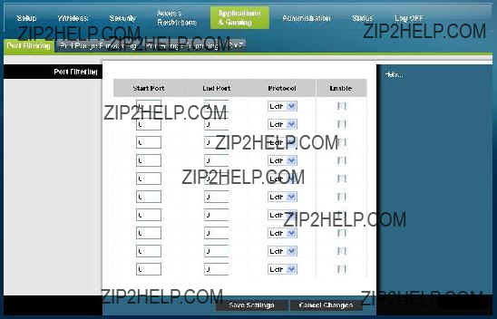
Applications & Gaming > Port Filtering
Use this window to configure transmission control protocol (TCP) and user datagram protocol (UDP) port filters. These filters prevent a range of TCP/UDP ports from accessing the Internet. You can also prevent PCs from sending outgoing TCP/UDP traffic to the WAN on specific IP port numbers. This filter is not IP address- or MAC address- specific. The system blocks the specified port ranges for all PCs.
Select the Port Filtering tab to open the Applications & Gaming Port Filtering page.
Applications and Gaming Port Filtering Page Description
Use the descriptions and instructions in the following table to configure the port filtering for applications and gaming features used on your residential gateway. Click the Enable checkbox to enable port forwarding for the relevant application. After you make your selections, click Save Settings to apply your changes or Cancel Changes to cancel.

Configure Applications and Gaming
End Port:
This is the end of the port range. Enter the end of the range of port numbers (external ports) used by the server or Internet application. Check with the software documentation of the Internet application for more information if necessary.
Protocol
Select one of the following protocols:
??? TCP
??? UDP
??? Both
Enable:
Check this box to enable filtering on the specified ports.
Applications & Gaming > Port Range Forwarding
Important: The gateway normally implements a feature called Port Translation. Port Translation monitors what ports are actually being used by your PCs or other devices on your LAN. This monitoring provides an added level of security beyond what the firewall provides. However, there are some applications that require the gateway to use specific ports to connect over the Internet.
Use Port Range Forwarding to forward ports from the public Internet to specific IP addresses in your local network. Select the Port Range Forwarding tab to open the Applications & Gaming Port Range Forwarding page.
For the Start and End Port, select a port from the recommended 49152 - 65535 range. Keep in mind that ports used are program specific so check which ones the program requires to be forwarded. Type the port number or range in both boxes. In the IP
Address box type the name of the computer???s IP address to which this is to apply.
Note: Port Range Forwarding continually exposes the selected ports to the public
Internet. This means that the gateway???s firewall is no longer active on these ports.
The device with the forwarding IP address can be exposed to hacker attacks while the port range is being forwarded.
Configure Applications and Gaming
Applications and Gaming Port Range Forward Page Description
Use the descriptions and instructions in the following table to configure the port range forwarding for the residential gateway. Select enable for each. After you make your selections, click Save Settings to apply your changes or Cancel Changes to cancel.
Port Range Forwarding Start
For the Start port, select a port from the recommended 49152 - 65535 range. Keep in mind that ports used are program specific so check which ones the program requires to be forwarded.
End
For the End port, select a port from the recommended 49152 - 65535 range. Keep in mind that ports used are program specific so check which ones the program requires to be forwarded.
Protocol
Select one of the following protocols:
???
???
???
TCP
UDP
Both
IP Address
Enter the computer???s IP address to which this is to apply.
Enable
Check this box to enable port forwarding for the specified ports and IP addresses.

Configure Applications and Gaming
Applications & Gaming > Port Range Triggering
Port range triggering is a way to dynamically forward ports to a LAN PC that needs them at a particular time. That particular time is when it runs a certain application that performs some event that trigger the router. This event must be an outbound access of a particular port range.
Select the Port Range Triggering tab to open the Applications & Gaming Port Range Triggering page.
Applications and Gaming Port Range Triggering Page Description
Use the descriptions and instructions in the following table to configure the port range triggering for the residential gateway. Select enable for each. After you make your selections, click Save Settings to apply your changes or Cancel Changes to cancel.
End Port
For the End port, select a port from the recommended 49152 - 65535 range. Keep in mind that ports used are program specific so check which ones the program requires to be forwarded.

???
???
???
TCP
UDP
Both
Enable
Click the Enable checkbox to enable port range triggering for the relevant application.
Applications & Gaming > DMZ
Use this page to configure an IP address whose ports are directly exposed to the public Internet or to the Wide Area Network (WAN). Demilitarized Zone (DMZ) hosting is commonly referred to as "exposed host," and allows you to specify a recipient of WAN traffic that Network Address Translation (NAT) is unable to translate to a known local PC.
A DMZ is typically used by a company that wants to host its own Internet server. DMZ allows one IP address to be placed on the Internet side of the gateway firewall while others remain protected behind the firewall.
The DMZ allows a device to be directly accessible to Internet traffic, such as a web (HTTP) server, an FTP server, an SMTP

Configure Applications and Gaming
Applications and Gaming DMZ Page Description
Use the descriptions and instructions in the following table to configure the port range triggering for the residential gateway. Select enable for each DMZ Host IP address. After you make your selections, click Save Settings to apply your changes or Cancel Changes to cancel.
???
???
Enable
Disable (factory default)
DMZ Host IP Address
DMZ allows one IP address to be unprotected while others remain protected. Enter the IP address of the computer you want to expose to the Internet in this field.

Manage the Gateway
Manage the Gateway
Administration > Management
The Administration Management page allows the network???s administrator to manage specific gateway functions for access and security. Select the Management tab to open the Administration Management page.
Important: The following page displays when DHCP (factory default) is the Connection Mode. The page that displays when Static IP is selected is shown and described later in this section.
Administration Management Page Description
Use the descriptions and instructions in the following table to configure the administration management for the residential gateway when DHCP or Static IP connection mode is selected. After you make your selections, click Save Settings to apply your changes or Cancel Changes to cancel.

Static IP
Allows you to specify the WAN IP address and corresponding server information as static or fixed values that will be used whenever the gateway goes online

Field
MTU
Manage the Gateway
Description
Internet IP Address
Enter the gateway???s IP address (as seen from the Internet)
Subnet Mask
Enter the gateway???s subnet mask (as seen from the Internet, including your service provider)
Default Gateway
Enter the default gateway of the service provider???s server
Primary DNS
Enter the primary domain name server IP address(es) provided by your service provider. This is required.
Secondary DNS
Enter the secondary domain name server IP address(es) provided by your service provider. This is optional.
MTU size
MTU is the Maximum Transmission Unit. The MTU size specifies the largest packet size permitted for Internet transmission. . The factory default = 0 (1500 bytes)
Gateway Access
Local Access
Current User Name
Identifies the currently logged in user
Change Current User Name to
This field allows you to change your user name. If you want to change your user name, enter your new user name in this field and click Save Settings to apply the change.
Note: The factory default user name is a blank field.
Change Password to
This field allows you to change your password. If you want to change your password, enter your new password in this field. Then,
Note: The factory default password is a blank field.
Allows you to

Manage the Gateway
Administration > Reporting
Administration reporting allows you to email various system activities to your email address.
Select the Reporting tab to open the Administration Reporting page.
Use the descriptions and instructions in the following table to configure the reporting feature on the gateway. After you make your selections, click Save Settings to apply your changes or Cancel Changes to cancel.
SMTP Mail Server
Enter the address (domain name) or IP address of the Simple Mail
Transport Protocol (SMTP) server you use for outgoing
Enter the

Manage the Gateway
View Log
To view the logs, complete the following steps.
1 Click View Log. A new window opens with the log data page.
2To view a particular log, select one of the following options from the Type drop- down menu:
???All
???Access Log
???Firewall Log
???VPN Log
3After the log data is displayed, use one of the following options:
???Click the Page Refresh button to update the log.
???Click the Clear button to clear all the information in the current log.
???Click the Previous Page button to go back to the information previously displayed.
???Click the Next Page button to see the next section of the log, if available.
Manage the Gateway
Administration > Diagnostics
Administration diagnostics allow you to check the status of your Internet connection by using a Ping test.
Select the Diagnostics tab to open the Administration Diagnostics page.
Use the descriptions and instructions in the following table to configure the diagnostics feature on the gateway. After you make your selections, click Save Settings to apply your changes or Cancel Changes to cancel.

Manage the Gateway
Administration > Backup & Restore
Administration Backup & Restore allows you to back up you configuration of the Gateway and store it on your computer. You can use this file to restore a previously saved configuration for your Gateway.
Select the Back Up & Restore tab to open the Administration Back Up & Restore page.

 CAUTION:
Restoring a configuration file will destroy (overwrite) all of the existing settings.
Back Up Configuration Use the Back Up Configuration feature to save a copy of the current configuration and store the file on your computer. Click Back Up to start the download.
Restore Configuration Use the Restore Configuration feature to restore a previously saved configuration file. Click Browse to select the configuration file, and then click Restore to load the configuration file to the device.
Manage the Gateway
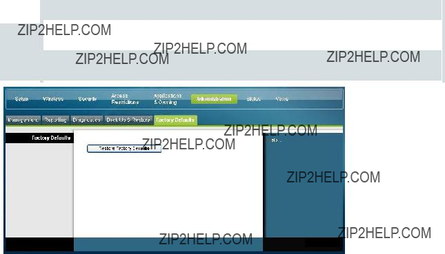
Administration > Factory Defaults
The Administration Factory Defaults page allows you to restore the configuration to its factory default settings. Select the Factory Defaults tab to open the Administration Factory Defaults page.

 CAUTION:
If you restore the factory defaults, the gateway will lose all of the settings you have entered. Before you reset the gateway to its factory default settings, write down all of your custom settings. After the defaults have been restored, you will have to
Restore Factory Defaults
To restore factory defaults, click Restore Factory Defaults to reset all configuration settings to their default values. Any settings you have saved will be lost when the default settings are restored.

Monitor Gateway Status
Monitor Gateway Status
This section describes the options available under the Status tab that you can use to monitor the status of the residential gateway and to perform diagnostics on the device and the network.
Status > Gateway
The Gateway Status page displays information about the gateway and its current settings. The
Select the Gateway tab to open the Status Gateway screen. Click Refresh to update the data displayed
Use the descriptions in the following table to review the status of your gateway and your Internet connection.

Status > Local Network
The Local Network Status page displays information about the status of the local area network.
Select the Local Network tab to open the Status Local Network page. Click Refresh to update the data on the page.
Use the following table to review the status of your gateway and your Internet connection.

IP Address
Displays the IP address for the LAN subnet
Subnet Mask
Displays the subnet mask for your LAN
DHCP Server
Displays the status of your local DHCP server (Enabled or Disabled)
Starting IP Address
Displays the beginning of the range of IP addresses used by the
DHCP server in your gateway
End IP Address
Displays the end of the range of IP addresses used by the DHCP server
DHCP Client Table Click DHCP Client Table to show which devices are attached to your LAN that have been isued IP addresses by the DHCP server in the gateway. On the DHCP Client Table page, you will see a list of DHCP clients (computers and other network devices) with the following information: Client Host Names, IP Addresses, MAC Addresses, and the length of time before their assigned IP addresses expire. To retrieve the most
The following illustration shows an example of the DHCP Client Table.

Monitor Gateway Status
ARP/RARP Table Click ARP/RARP Table to see a complete list of all devices that are connected to your network. To retrieve the most
The following illustration shows an example of the ARP/RARP Table.
Status > Wireless
The Wireless Network Status page displays basic information about the wireless network of the gateway.
Select the Wireless tab to open the Status Wireless page. Click Refresh to update the data on the page.

Monitor Gateway Status
Status Wireless Page Description
Use the following table to review the status of your wireless network.
???
???
???
2.4 GHz
5 GHz
2.4 and 5 GHz
Note: Not all products support the 5 GHz radio band.
Network Name (SSID)
Displays the name or service set identifier (SSID) of your wireless access point
Channel Width
Displays the channel bandwidth setting selected on the Basic
Wireless Settings page
Wide Channel
Displays the Wide Channel setting selected on the Basic Wireless
Settings page
Standard Channel
Displays the Standard Channel setting selected on the Basic
Wireless Settings page
Security
Displays the security method used by your wireless network
SSID Broadcast
Displays the status of the gateway's SSID Broadcast feature

Monitor Gateway Status
Status > DOCSIS WAN
DOCSIS WAN Status displays information about the system of your cable modem. Select the DOCSIS WAN tab to open the Status DOCSIS WAN page.
DOCSIS WAN Page Description
Use the descriptions in the following table to review the status of your DOCSIS WAN network.

Frequently Asked Questions
Frequently Asked Questions
Q.How Do I Configure TCP/IP Protocol?
A.To configure TCP/IP protocol, you need to have an Ethernet Network Interface
Card (NIC) with TCP/IP communications protocol installed on your system. TCP/IP is a communications protocol used to access the Internet. This section contains instructions for configuring TCP/IP on your Internet devices to operate with the residential gateway in Microsoft Windows or Macintosh environments.
TCP/IP protocol in a Microsoft Windows environment is different for each operating system. Follow the appropriate instructions in this section for your operating system.
Configuring TCP/IP on Windows 2000 Systems
1Click Start, select Settings, and choose Network and
2
3Click Properties in the Local Area Connection Status window.
4Click Internet Protocol (TCP/IP) in the Local Area Connection Properties window, and then click Properties.
5Select both Obtain an IP address automatically and Obtain DNS server address automatically in the Internet Protocol (TCP/IP) Properties window, and then click OK.
6Click Yes to restart your computer when the Local Network window opens. The computer restarts. The TCP/IP protocol is now configured on your PC, and your Ethernet devices are ready for use.
7Try to access the Internet. If you cannot access the Internet, contact your service provider for further assistance.
Configuring TCP/IP on Windows XP Systems
1Click Start, and depending on your Start menu setup, choose one of the following options:
???If you are using the Windows XP Default Start Menu, select Connect to, choose Show all connections, and then go to step 2.
???If you are using the Windows XP Classic Start Menu, select Settings, choose
Network Connections, click Local Area Connection, and then go to step 3.
2
3Click Properties in the Local Area Connection Status window.
4Click Internet Protocol (TCP/IP), and then click Properties in the Local Area Connection Properties window.
Frequently Asked Questions
5Select both Obtain an IP address automatically and Obtain DNS server address automatically in the Internet Protocol (TCP/IP) Properties window, and then click OK.
6Click Yes to restart your computer when the Local Network window opens. The computer restarts. The TCP/IP protocol is now configured on your PC, and your Ethernet devices are ready for use.
7Try to access the Internet. If you cannot access the Internet, contact your service provider for further assistance.
Configuring TCP/IP on Macintosh Systems
1Click the Apple icon in the
Control Panels, and then click TCP/IP.
2Click Edit on the Finder at the top of the page. Scroll down to the bottom of the menu, and then click User Mode.
3Click Advanced in the User Mode window, and then click OK.
4Click the Up/Down selector arrows located to the right of the Connect Via section of the TCP/IP window, and then click Using DHCP Server.
5Click Options in the TCP/IP window, and then click Active in the TCP/IP Options window.
Note: Make sure that the Load only when needed option is unchecked.
6Verify that the Use 802.3 option located in the
7Is there a Hardware Address listed in this window?
???If yes, click OK. To close the TCP/IP Control Panel window, click File, and then scroll down to click Close. You have completed this procedure.
???If no, you must power off your Macintosh.
8With the power off, simultaneously press and hold down the Command (Apple), Option, P, and R keys on your keyboard. Keeping those keys pressed down, power on your Macintosh but do not release these keys until you hear the Apple chime at least three times, then release the keys and let the computer restart.
9When your computer fully reboots, repeat steps 1 through 7 to verify that all TCP/IP settings are correct. If your computer still does not have a Hardware Address, contact your authorized Apple dealer or Apple technical support center for further assistance.
Frequently Asked Questions
Renewing the IP Address on Windows 95, 98, 98SE, and ME Systems
1Click Start, and then click Run to open the Run window.
2Type winipcfg in the Open field, and click OK to execute the winipcfg command. The IP Configuration window opens.
3Click the down arrow to the right of the top field, and select the Ethernet adapter that is installed on your PC. The IP Configuration window displays the Ethernet adapter information.
4Click Release, and then click Renew. The IP Configuration window displays a new IP address.
5Click OK to close the IP Configuration window, you have completed this procedure.
Note: If you cannot access the Internet, contact your service provider for further assistance.
Renewing the IP Address on Windows NT, 2000, or XP Systems
1Click Start, and then click Run. The Run window opens.
2Type cmd in the Open field and click OK. A window with a command prompt opens.
3Type ipconfig/release at the C:/ prompt and press Enter. The system releases the IP address.
4Type ipconfig/renew at the C:/ prompt and press Enter. The system displays a new IP address.
5Click the X in the
Note: If you cannot access the Internet, contact your service provider for further assistance.
Q.What if I don't subscribe to cable TV?
A.If cable TV is available in your area, data service may be made available with or without subscribing to cable TV service. Contact your local service provider for complete information on cable services, including
Q.How do I arrange for installation?
A.Call your service provider to inquire about professional installation. A professional installation ensures proper cable connection to the modem and to your PC, and it ensures the proper configuration of all hardware and software settings. Contact your service provider for more information about installation.
Frequently Asked Questions
Q.How does the residential gateway connect to my computer?
A.The residential gateway connects to the PC using a wireless connection or the
Q.After my residential gateway is connected, how do I access the Internet?
A.Your local service provider becomes your Internet Service Provider (ISP). They offer a wide range of services including
Q.Can I watch TV and surf the Internet at the same time?
A.Absolutely! If you subscribe to cable television service, you can watch TV and use your residential gateway at the same time by connecting your TV and your residential gateway to the cable network using an optional cable signal splitter.
Common Troubleshooting Issues
I don't understand the front panel status indicators
See Front Panel LED Status Indicator Functions (on page 96), for more detailed information on front panel LED status indicator operation and function.
The residential gateway does not register an Ethernet connection
???Verify that your computer has an Ethernet card and that the Ethernet driver software is properly installed. If you purchase and install an Ethernet card, follow the installation instructions very carefully.
???Verify the status of the front panel status indicator lights.
The residential gateway does not register an Ethernet connection after connecting to a hub
If you are connecting multiple PCs to the residential gateway, you should first connect the modem to the uplink port of the hub using the correct crossover cable. The LINK LED of the hub will illuminate continuously.
The residential gateway does not register a cable connection
???The modem works with a standard
???Your NIC card or USB interface may be malfunctioning. Refer to the troubleshooting information in the NIC or USB documentation.
Tips for Improved Performance
Tips for Improved Performance
Check and Correct
If your residential gateway does not perform as expected, the following tips may help. If you need further assistance, contact your service provider.
???Verify that the plug to your residential gateway AC power is properly inserted into an electrical outlet.
???Verify that your residential gateway AC power cord is not plugged into an electrical outlet that is controlled by a wall switch. If a wall switch controls the electrical outlet, make sure the switch is in the ON position.
???Verify that the ONLINE LED status indicator on the front panel of your residential gateway is illuminated.
???Verify that your cable service is active and that it supports
???Verify that all cables are properly connected, and that you are using the correct cables.
???Verify that your TCP/IP is properly installed and configured if you are using the Ethernet connection.
???Verify that you have called your service provider and given them the serial number and MAC address of your residential gateway.
???If you are using a cable signal splitter so that you can connect the residential gateway to other devices, remove the splitter and reconnect the cables so that the residential gateway is connected directly to the cable input. If the residential gateway now functions properly, the cable signal splitter may be defective and may need to be replaced.
???For best performance over an Ethernet connection, your PC should be equipped with a Gigabit Ethernet card.

Front Panel LED Status Indicator Functions
Front Panel LED Status Indicator Functions
Initial Power Up, Calibration, and Registration (AC Power applied)
The following chart illustrates the sequence of steps and the corresponding appearance of the residential gateway front panel LED status indicators during power up, calibration, and registration on the network when AC power is applied to the residential gateway. Use this chart to troubleshoot the power up, calibration, and registration process of your residential gateway.
Note: After the residential gateway completes Step 6 (Request
Normal Operations (AC Power applied) (on page 98).
Front Panel LED Status Indicators During Initial Power Up, Calibration, and Registration

Front Panel LED Status Indicator Functions
Front Panel LED Status Indicators During
Initial Power Up, Calibration, and Registration
High Speed Data Registration (continued)

Front Panel LED Status Indicator Functions
Normal Operations (AC Power applied)
The following chart illustrates the appearance of the residential gateway front panel LED status indicators during normal operations when AC power is applied to the gateway.
Front Panel LED Status Indicators During Normal Conditions

Front Panel LED Status Indicator Functions
Special Conditions
The following chart describes the appearance of the cable modem front panel LED status indicators during special conditions to show when you have been denied network access.
Front Panel LED Status Indicators During Special Conditions
Notices
Notices
Trademarks
Cisco and the Cisco logo are trademarks or registered trademarks of Cisco and/or its affiliates in the U.S. and other countries. A listing of Cisco's trademarks can be found at www.cisco.com/go/trademarks.
DOCSIS is a registered trademark of Cable Television Laboratories, Inc. EuroDOCSIS, EuroPacketCable, and PacketCable are trademarks of Cable Television Laboratories, Inc. The
Other third party trademarks mentioned are the property of their respective owners.
The use of the word partner does not imply a partnership relationship between Cisco and any other company. (1009R)
Publication Disclaimer
Cisco Systems, Inc. assumes no responsibility for errors or omissions that may appear in this publication. We reserve the right to change this publication at any time without notice. This document is not to be construed as conferring by implication, estoppel, or otherwise any license or right under any copyright or patent, whether or not the use of any information in this document employs an invention claimed in any existing or later issued patent.
The maximum performance for wireless is derived from IEEE Standard 802.11 specifications. Actual performance can vary, including lower wireless network capacity, data throughput rate, range and coverage. Performance depends on many factors, conditions and variables, including distance from the access point, volume of network traffic, building materials and construction, operating system used, mix of wireless products used, interference and other adverse conditions.
Copyright
?? 2010, 2012 Cisco and/or its affiliates. All rights reserved. Printed in the United States of America.
Information in this publication is subject to change without notice. No part of this publication may be reproduced or transmitted in any form, by photocopy, microfilm, xerography, or any other means, or incorporated into any information retrieval system, electronic or mechanical, for any purpose, without the express permission of Cisco Systems, Inc.
Notices
Software and Firmware Use
The software described in this document is protected by copyright law and furnished to you under a license agreement. You may only use or copy this software in accordance with the terms of your license agreement.
The firmware in this equipment is protected by copyright law. You may only use the firmware in the equipment in which it is provided. Any reproduction or distribution of this firmware, or any portion of it, without our express written consent is prohibited.
For Information
For Information
If You Have Questions
If you have technical questions, call Cisco Services for assistance. Follow the menu options to speak with a service engineer.
For Information

This document includes various trademarks of Cisco Systems, Inc. Please see the Notices section of this document for a list of the Cisco Systems, Inc. trademarks used in this document.
Product and service availability are subject to change without notice.