NEXT
SETUP INSTRUCTIONS
CF2001P
Printer
WARNING
??? Do not plug in the power cord or turn on this unit until you are instructed to according to this manual.
CAUTION
???Install this machine so that it can quickly be unplugged from the electrical outlet in case of an emergency. The socket-outlet shall be installed near the machine and shall be easily accessible.
???Keep all packing materials out of the reach of children.
NOTE
???If the CF2001P is connected to the Minolta MircroPress Cluster Printing System, be sure to take back the User Manual for the CF2001P, since it is not needed by the customer.
???Keep all packing materials in a safe place for later use in case they are needed for transportation.
1.Remove the accessories from the box, and then check that the following are
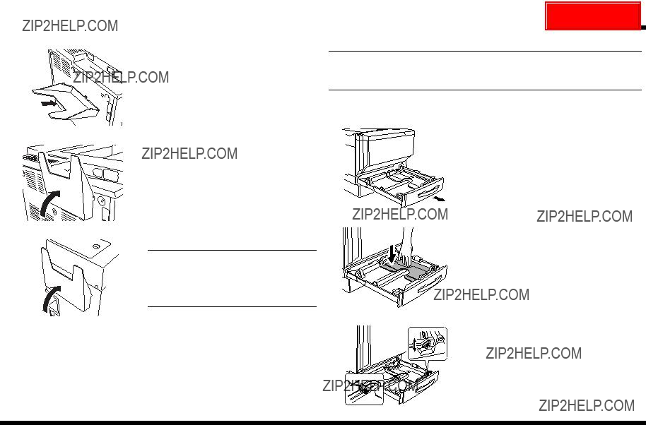
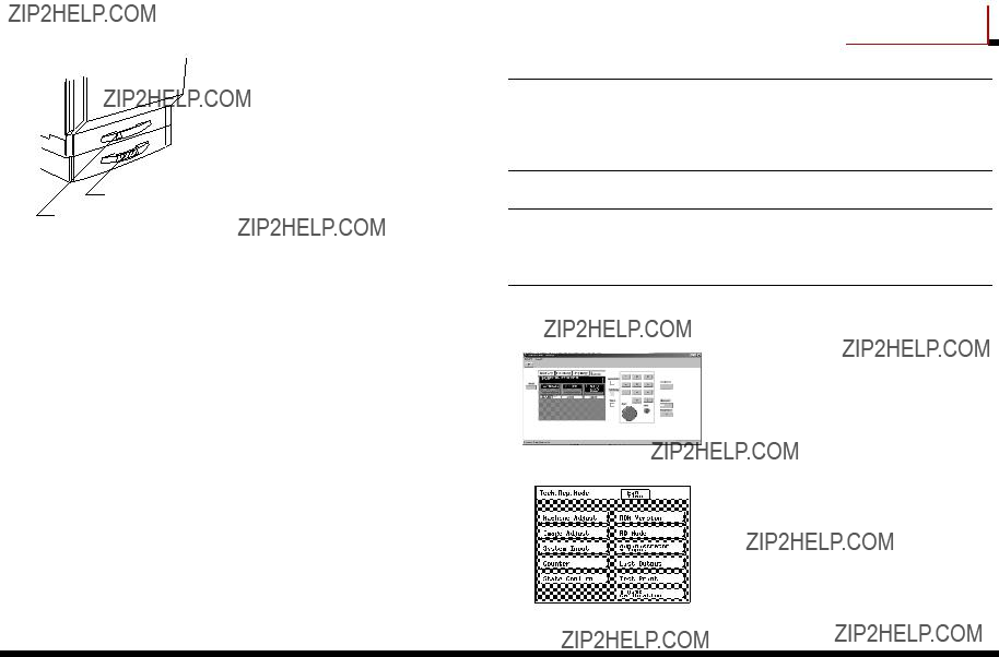
??? Removing the Protective Tape and Packing Materials
<Outside Surface of the Printer>
Remove the tape affixed to the outside sur- face of the printer.
C4004U145AA
C4004U005AA
Paper take-up
 roller
 Packing


 material
C4004U006AA
3.Remove the 2 pieces of packing material from the paper-lifting plate.
4.Close the paper drawer.
5.Pull out the paper drawer for Tray 2.
NOTE
Be careful not to touch the surface of the paper take-up roller with your hands. If the roller has been touched, wipe it with a dry cloth.
6.Remove the 3 pieces of tape affixed to the paper-lifting plate as shown.
<Paper Feed Section>
Packing
 material
Paper take-up roller
1. Pull out the paper drawer for Tray 1.
NOTE
Be careful not to touch the surface of the paper take-up roller with your hands. If the roller has been touched, wipe it with a dry cloth.
7.Remove the packing material from the paper-lifting plate.
8 Close the paper drawer.
C4004U024AA
2.Remove the 2 pieces of tape shown in the illustration from the paper-lifting plate.
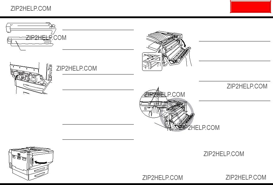
6.Fully pull the toner hopper shutter out toward you. Pulling out the toner hopper shutter allows the toner to begin filling the toner hop- per. Check that all of the toner has emptied out of the toner bottle and into the hopper, which may take a while.
9. Carefully close the yellow toner hopper lid.
NOTE
Do not tap on the toner bottle while refilling the hopper; otherwise, the toner may spurt out.
10.Fill the magenta, cyan, and black toner in the same way (as described in steps 2 through 9).
NOTE
Be sure to fill the toner hoppers with the cor- rect color of toner.
7.Push the toner hopper shutter closed until it snaps into place and closes the bottle.
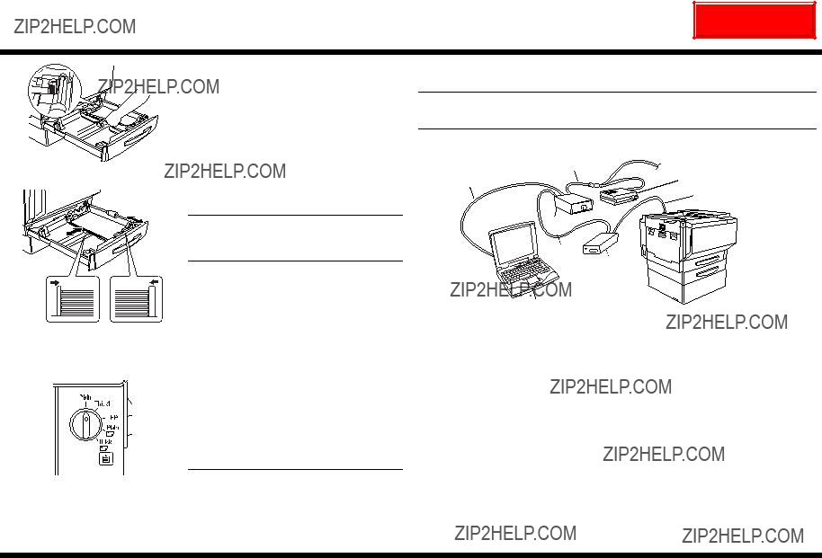
11.After all four toner hoppers are filled, grasp the toner supply door as shown, and then carefully swing the door down to close it.
C4004U067AA
8.Tilt the toner bottle slightly backward, and then pull the opening of the bottle up and toward you to remove it.
C4004U065AB
4. Connecting the Cables
1. Make sure that the printer power cord is not plugged into the electrical outlet, and then insert the plug on the end of the power cord into the power cord connector on the printer.
5. Affixing the Support Label
Support label
Affix the support label on the right side of the top of the toner supply door.
NOTE
Affix the label that corresponds with the installed options.
2.Insert the plug on the other end of the power cord into an electrical outlet.
C4004U139CA
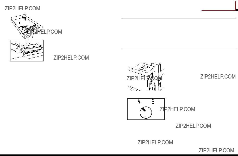
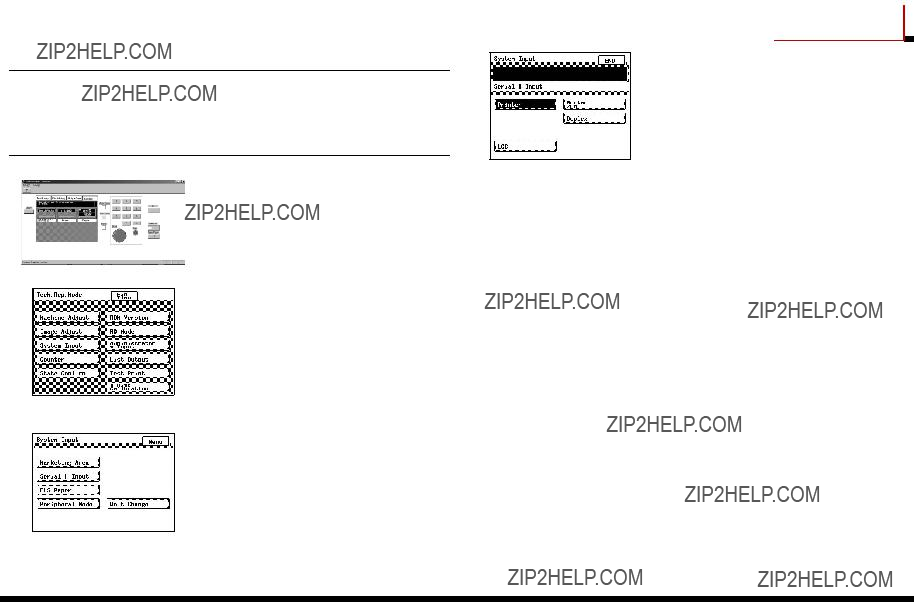
8. Making System Setting
??? Checking the Date Setting
1.Check that the External Panel Controller appears in the computer screen, and then display the Date/Time Input screen. (For details about displaying the Date/Time Input screen, refer to the Service Manual.)
C4004P565CA
3. Click [END].
C4004PU09CA
4.Click [Menu].
5.Check that the Basic screen appears on the External Panel Controller.
C4004PU07CA
2.Check that the current date and time settings are correct. If the settings are not correct, use the keypad in the External Panel Con- troller to enter the correct date and time in the upper row of the screen.
Example)
To specify April 1, 2001 15:30, click:
[2], [0], [0], [1], [0], [4], [0], [1], [1], [5], [3], [0]
C4004PU08CA
???Specifying the Serial Number
NOTE
Be sure to specify the serial number.
When the serial number is specified, the settings for each unit can be read by the printer. If the serial number is not specified, a correctly adjusted image cannot be printed.
4.Make sure that [Printer] is selected. Using the keypad in the External Panel Controller, enter the printer???s serial number.
Repeat this step to enter the serial numbers for [LCC], [Sorter/FN], and [Duplex].
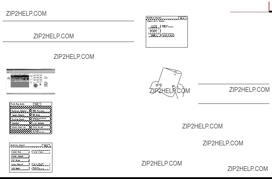
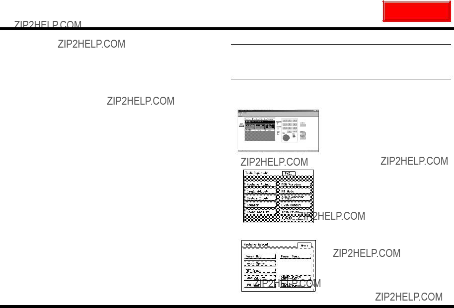
1.Check that the External Panel Controller appears in the computer screen, and then display the Tech. Rep. Mode screen.(For details about displaying the Tech. Rep. Mode screen, refer to the Service Manual.)
5.Click [END].
6.Click [Menu], and then click [Fin. Time].
C4004P565CA
2. Click [System Input].
C4004P597CA
3. Click [Serial # Input].
C4004P584CA
10.Check that the External Panel Controller appears in the computer screen, and then display the Tech. Rep. Mode screen. (For details about displaying the Tech. Rep. Mode screen, refer to the Service Manual.)
C4004P565CA
11. Click [List Output].
15.Check that the message displayed in the control panel changes from ???Alert Printing suspended??? to ???Info???.
16.Exit the External Panel Controller.
NOTE
Before connecting or disconnecting the har- nesses of the IR port cable, be sure to turn off the printer and the converter.
C4004P597CA
12. Click [Image Processing].
C4004PU10CA
13.Click the [Start] key in the External Panel Controller. A list of image processing set- tings and the values of each counter are printed out on four sheets of A4(L)-size (or Letter(C)-size) plain paper.
14.Click [Menu], and then click [Fin. Time].
8.Affix the enclosed paper size label to Tray 2 as shown.
9.Affix the enclosed drawer number label as
shown.
Paper size label
Drawer number label
C4004U141AA
10.Adjusting the Options
NOTE
???With the CF2001P, the adjustments of each option are performed with the servicing equipment. Therefore, start up the External Panel Controller, and make the adjustments with the appropriate setting.
???After adjusting the options, restart the printer.
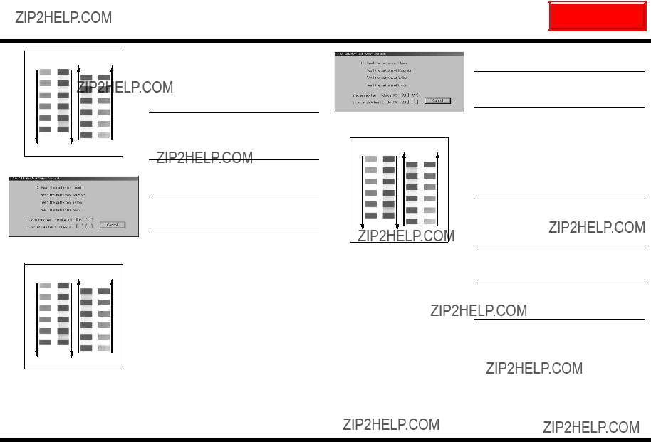
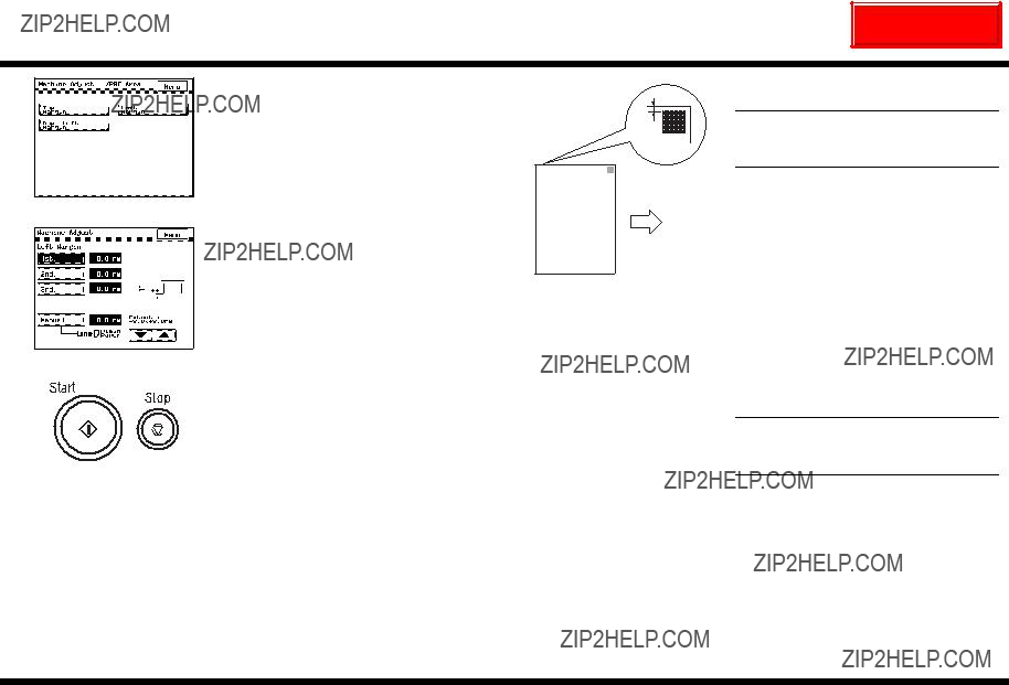
???Checking the Paper Reference Position for PF-118
NOTE
???For details on the installing PF-118, refer to its Setup Instructions.
???To adjust PF-118, follow the instructions below.
???To exit the External Panel Controller, refer to step 14 on page 24.
1.Load A4-size (or Letter-size) paper into the paper drawer of the optional paper feed unit.
2.Check that the External Panel Controller appears in the computer screen, and then display the Tech. Rep. Mode screen. (For details about displaying the Tech. Rep. Mode screen, refer to the Service Manual.)
C4004P565CA
3. Click [Machine Adjust].
C4004P597CA
4. Click [PRT Area].
C4004P588CA
5. Click [Left Margin].
Standard width of the margin (a):
3.0 mm ?? 1.0 mm (with Fiery X3e installed)
5.0 mm ?? 1.0 mm (with MicroPress PrintLink
2020m installed)
If the width of the measured margin does not meet its standard width, follow the procedure in the next section, ???Adjusting the Paper Ref- erence Position for PF-118???, to adjust it.
C4658U028AA
C4658P003CA
6.Select the key for the paper drawer that is to be adjusted, and then click the Start key in the External Panel Controller.
A test page is printed.
C4658P005CA
10.Check that the message displayed in the control panel changes from ???Alert Printing suspended??? to ???Info???.
11.Exit the External Panel Controller.
??? Checking and Adjusting the Paper Reference Position for PF-117
NOTE
???For details on the installing PF-117, refer to its Setup Instructions.
???To adjust PF-117, follow the instructions below.
???To exit the External Panel Controller, refer to step 14 on page 24.
1.Load A4-size (or Letter-size) paper into the paper drawer of the large-capacity cabinet.
2.Check that the External Panel Controller appears in the computer screen, and then display the Tech. Rep. Mode screen. (For details about displaying the Tech. Rep. Mode screen, refer to the Service Manual.)
C4004P565CA
3. Click [Machine Adjust].
C4004P597CA
4. Click [PRT Area].
C4004P588CA
???Checking the Hole-Punching Positions for FN-107
NOTE
???For details on the installing FN-107, refer to its Setup Instructions.
???To adjust FN-107, follow the instructions below.
???To exit the External Panel Controller, refer to step 14 on page 24.
1.Unplug the power cord, and then turn off the printer.
2.Load A4-size (or Letter-size) paper (in land- scape orientation) into Tray 1.
6. Click [Hole-Punch].
C4683P005CA
7.Click the Start key in the External Panel Controller.
3.Check that the External Panel Controller appears in the computer screen, and then display the Tech. Rep. Mode screen. (For details about displaying the Tech. Rep. Mode screen, refer to the Service Manual.)
C4004P565CA
4. Click [Machine Adjust].
8.Fold the paper that is fed out in half, and check that the punched holes are aligned.
Standard position: ??2mm
NOTE
If the punched holes are not at their stan- dard positions, adjust the hole-punching
4643U031AA position.
C4004P597CA
5. Click [Staple/Hole-Punch].
C4004P588CA
???Setting DT-105 (USA and Canada only)
NOTE
???For details on installing DT-105, refer to the Setup Instructions included with it.
???To set the DT-105, follow the instructions below.
???To exit the External Panel Controller, refer to step 14 on page 24.
<Connecting the Telephone Cables>
??? Connect the telephone cable to the jack marked ???LINE??? on the data terminal.
NOTE
If the telephone cable is too short, obtain a different cable with modular plugs.
???Connection examples
<When the telephone line is only for the data terminal>
4656M007CA
<When the telephone line is for a phone and the data terminal>
4656M008CA
<When the telephone line is only for a fax, phone and data terminal>
4656M009CA
NOTE
For details on connecting the fax, refer to the manual for the fax machine.
NEXT
CF2001P
1. Click [Date/Time Input].
C4656P004CA
3.Select the dial mode of the user???s telephone line.
4. Click [END].
C4656P005CA
5. Click [Auto Receive].
C4656P003CA
2.Click [Year], click the Clear key in the External Panel Controller, and then use the keypad in the External Panel Controller to enter the correct year.
3.Enter the correct settings for [Month], [Date], and [Hour].
C4656P007CA
4. Click [SET].
C4656P004CA
6.Click [Disable].
7.Click [END] twice.
C4656P006CA
<Maintenance Center (Billing Center) Settings>
NOTE
The procedure for making Maintenance Center settings are described below. If Billing Center settings are necessary, specify them using the same procedure after entering the Maintenance Center settings.
<Clearing the Maintenance RAM>
1.Click [Maintenance].
(For the Billing Center, click [Billing].)
4.Click [ID Code] again so that it appears in black on a white background.
5.Click [RAM Clear].
C4656P010CA
6. Click [Yes].
7. Click [END].
2.Click [ID Code] so that it appears in white on a black background.
NOTE
For the Billing Center, there is no need to enter an ID code.
C4656P008CA
3.Using the keypad in the External Panel Controller, enter the 7-digit ID code.
NOTE
Enter the service representative???s ID code.
C4656P009CA
<DT Settings>
1.Click [ID Code] so that it appears in white on a black background.
C4656P008CA
2.Using the keypad in the External Panel Controller, enter the 7-digit ID code.
NOTE
Enter the service representative???s ID code.
C4656P009CA
3.Click [ID Code] again so that it appears in black on a white background.
4.Click [DT Setting].
6.Using the keypad in the External Panel Controller, enter the 4-digit Center ID.
Password: Center ID code; identification number of the Center that the data terminal connects to
C4656P013CA
7.Click [DT-ID] so that it appears in white on a black background.
C4656P014CA
8.Using the keypad in the External Panel Controller, enter the 6-digit data terminal ID.
NOTE
If the number is not 6-digits long, add ???0??? at the beginning.
C4656P010CA
5.Click [Password] so that it appears in white on a black background.
C4656P012CA
<Initial Transmission>
???To perform the initial user registration for the data terminal after the initial settings have been specified, connect to the Center so the initial information can be sent to the data terminal.
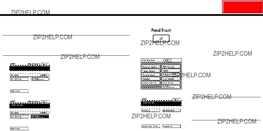
3.Click the Panel Reset key in the External Panel Controller.
4. Click [Fin. Time].
1. Click [Initial Transmission].
C4004P566CA
C4656P010CA
2.After the initial transmission is completed, check that ???End normal.??? appears on the screen.
NOTE
This completes input of the Maintenance Center settings. If the Billing Center settings must be specified, perform it in the same way.


 *
*


 1
1


 and
and  in the