Cisco Aironet 1400 Series Wireless Bridge
Hardware Installation Guide
August 2006
Corporate Headquarters
Cisco Systems, Inc. 170 West Tasman Drive
San Jose, CA
USA http://www.cisco.com Tel: 408
800
Text Part Number:
Cisco Aironet 1400 Series Wireless Bridge
Hardware Installation Guide
August 2006
Corporate Headquarters
Cisco Systems, Inc. 170 West Tasman Drive
San Jose, CA
USA http://www.cisco.com Tel: 408
800
Text Part Number:
THE SPECIFICATIONS AND INFORMATION REGARDING THE PRODUCTS IN THIS MANUAL ARE SUBJECT TO CHANGE WITHOUT NOTICE. ALL
STATEMENTS, INFORMATION, AND RECOMMENDATIONS IN THIS MANUAL ARE BELIEVED TO BE ACCURATE BUT ARE PRESENTED WITHOUT
WARRANTY OF ANY KIND, EXPRESS OR IMPLIED. USERS MUST TAKE FULL RESPONSIBILITY FOR THEIR APPLICATION OF ANY PRODUCTS.
THE SOFTWARE LICENSE AND LIMITED WARRANTY FOR THE ACCOMPANYING PRODUCT ARE SET FORTH IN THE INFORMATION PACKET THAT
SHIPPED WITH THE PRODUCT AND ARE INCORPORATED HEREIN BY THIS REFERENCE. IF YOU ARE UNABLE TO LOCATE THE SOFTWARE LICENSE
OR LIMITED WARRANTY, CONTACT YOUR CISCO REPRESENTATIVE FOR A COPY.
The following information is for FCC compliance of Class A devices: This equipment has been tested and found to comply with the limits for a Class A digital device, pursuant to part 15 of the FCC rules. These limits are designed to provide reasonable protection against harmful interference when the equipment is operated in a commercial environment. This equipment generates, uses, and can radiate
The following information is for FCC compliance of Class B devices: The equipment described in this manual generates and may radiate
Modifying the equipment without Cisco???s written authorization may result in the equipment no longer complying with FCC requirements for Class A or Class B digital devices. In that event, your right to use the equipment may be limited by FCC regulations, and you may be required to correct any interference to radio or television communications at your own expense.
You can determine whether your equipment is causing interference by turning it off. If the interference stops, it was probably caused by the Cisco equipment or one of its peripheral devices. If the equipment causes interference to radio or television reception, try to correct the interference by using one or more of the following measures:
???Turn the television or radio antenna until the interference stops.
???Move the equipment to one side or the other of the television or radio.
???Move the equipment farther away from the television or radio.
???Plug the equipment into an outlet that is on a different circuit from the television or radio. (That is, make certain the equipment and the television or radio are on circuits controlled by different circuit breakers or fuses.)
Modifications to this product not authorized by Cisco Systems, Inc. could void the FCC approval and negate your authority to operate the product.
The Cisco implementation of TCP header compression is an adaptation of a program developed by the University of California, Berkeley (UCB) as part of UCB???s public domain version of the UNIX operating system. All rights reserved. Copyright ?? 1981, Regents of the University of California.
NOTWITHSTANDING ANY OTHER WARRANTY HEREIN, ALL DOCUMENT FILES AND SOFTWARE OF THESE SUPPLIERS ARE PROVIDED ???AS IS??? WITH
ALL FAULTS. CISCO AND THE
LIMITATION, THOSE OF MERCHANTABILITY, FITNESS FOR A PARTICULAR PURPOSE AND NONINFRINGEMENT OR ARISING FROM A COURSE OF
DEALING, USAGE, OR TRADE PRACTICE.
IN NO EVENT SHALL CISCO OR ITS SUPPLIERS BE LIABLE FOR ANY INDIRECT, SPECIAL, CONSEQUENTIAL, OR INCIDENTAL DAMAGES, INCLUDING,
WITHOUT LIMITATION, LOST PROFITS OR LOSS OR DAMAGE TO DATA ARISING OUT OF THE USE OR INABILITY TO USE THIS MANUAL, EVEN IF CISCO
OR ITS SUPPLIERS HAVE BEEN ADVISED OF THE POSSIBILITY OF SUCH DAMAGES.
CCSP, CCVP, the Cisco Square Bridge logo, Follow Me Browsing, and StackWise are trademarks of Cisco Systems, Inc.; Changing the Way We Work, Live, Play, and Learn, and iQuick Study are service marks of Cisco Systems, Inc.; and Access Registrar, Aironet, BPX, Catalyst, CCDA, CCDP, CCIE, CCIP, CCNA, CCNP, Cisco, the Cisco Certified Internetwork Expert logo, Cisco IOS, Cisco Press, Cisco Systems, Cisco Systems Capital, the Cisco Systems logo, Cisco Unity, Enterprise/Solver, EtherChannel, EtherFast, EtherSwitch, Fast Step, FormShare, GigaDrive, GigaStack, HomeLink, Internet Quotient, IOS, IP/TV, iQ Expertise, the iQ logo, iQ Net Readiness Scorecard, LightStream, Linksys, MeetingPlace, MGX, the Networkers logo, Networking Academy, Network Registrar, Packet, PIX,
All other trademarks mentioned in this document or Website are the property of their respective owners. The use of the word partner does not imply a partnership relationship between Cisco and any other company. (0601R)
Cisco Aironet 1400 Series Wireless Bridge Hardware Installation Guide.
??2006 Cisco Systems, Inc. All rights reserved.

C O N T E N T S
Contents

Contents

Contents
Cisco Aironet 1400 Series Wireless Bridge Hardware Installation Guide.

Preface
This section describes the objectives, audience, organization, and conventions of the Cisco Aironet 1400 Series Wireless Bridge Hardware Installation Guide.
Objectives
This publication explains the steps for initial setup and basic configuration of the Cisco Aironet 1400 Series Wireless Bridge (hereafter called the bridge) supporting
Audience
This publication is for the person installing and configuring a bridge for the first time. The installer should be familiar with network structures, terms, and concepts.
Organization
This guide contains the following sections:
Chapter 1, ???Overview,??? describes the major components, features, and specifications of the bridge.
Chapter 2, ???Installation Overview,??? provides warnings, safety information, and information needed before you begin the installation of your bridge system.
Chapter 3, ???Mounting and Alignment Overview,??? provides an overview of components and features used during bridge mounting and antenna alignment operations.
Chapter 4, ???Stacking Bridges,??? describes the how to install and verify stacked bridges for increased bandwidth.
Chapter 5, ???Configuring the Bridge for the First Time,??? describes how to enter basic bridge configuration settings.
Chapter 6, ???Troubleshooting,??? provides solutions to potential problems encountered during setup.
Appendix A, ???Translated Safety Warnings,??? lists translations of the safety warnings in this publication.
Appendix B, ???Declarations of Conformity and Regulatory Information,??? describes the regulatory conventions to which the bridge conforms and provides guidelines for operating bridges in Japan.
Cisco Aironet 1400 Series Wireless Bridge Hardware Installation Guide.
Preface
Conventions
Appendix C, ???Channels and Maximum Power Levels,??? describes the channels and maximum power levels supported by the regulatory organizations.
Appendix D, ???Assembling the Rooftop or Wall Mount,??? provides assembly instructions for the optional rooftop or wall mount.
Conventions
This publication uses the following conventions to convey instructions and information:
??? Commands and keywords are in boldface type.
Note Means reader take note. Notes contain helpful suggestions or references to materials not contained in this manual.
Caution Means reader be careful. In this situation, you might do something that could result in equipment damage or loss of data.
Warning This warning symbol means danger. You are in a situation that could cause bodily injury. Before you work on any equipment, be aware of the hazards involved with electrical circuitry and be familiar with standard practices for preventing accidents. (To see translations of the warnings that appear in this publication, refer to the appendix ???Translated Safety Warnings.???)
Waarschuwing Dit waarschuwingssymbool betekent gevaar. U verkeert in een situatie die lichamelijk letsel kan veroorzaken. Voordat u aan enige apparatuur gaat werken, dient u zich bewust te zijn van de bij elektrische schakelingen betrokken risico???s en dient u op de hoogte te zijn van standaard maatregelen om ongelukken te voorkomen. (Voor vertalingen van de waarschuwingen die in deze publicatie verschijnen, kunt u het aanhangsel ???Translated Safety Warnings??? (Vertalingen van veiligheidsvoorschriften) raadplegen.)
Varoitus T??m?? varoitusmerkki merkitsee vaaraa. Olet tilanteessa, joka voi johtaa ruumiinvammaan. Ennen kuin ty??skentelet mink????n laitteiston parissa, ota selv???? s??hk??kytkent??ihin liittyvist?? vaaroista ja tavanomaisista onnettomuuksien ehk??isykeinoista. (T??ss?? julkaisussa esiintyvien varoitusten k????nn??kset l??yd??t liitteest?? "Translated Safety Warnings" (k????nnetyt turvallisuutta koskevat varoitukset).)
Attention Ce symbole d???avertissement indique un danger. Vous vous trouvez dans une situation pouvant entra??ner des blessures. Avant d???acc??der ?? cet ??quipement, soyez conscient des dangers pos??s par les circuits ??lectriques et
Cisco Aironet 1400 Series Wireless Bridge Hardware Installation Guide.

Preface
Related Publications
Warnung Dieses Warnsymbol bedeutet Gefahr. Sie befinden sich in einer Situation, die zu einer K??rperverletzung f??hren k??nnte. Bevor Sie mit der Arbeit an irgendeinem Ger??t beginnen, seien Sie sich der mit elektrischen Stromkreisen verbundenen Gefahren und der Standardpraktiken zur Vermeidung von Unf??llen bewu??t. (??bersetzungen der in dieser Ver??ffentlichung enthaltenen Warnhinweise finden Sie im Anhang mit dem Titel ???Translated Safety Warnings??? (??bersetzung der Warnhinweise).)
Avvertenza Questo simbolo di avvertenza indica un pericolo. Si ?? in una situazione che pu?? causare infortuni. Prima di lavorare su qualsiasi apparecchiatura, occorre conoscere i pericoli relativi ai circuiti elettrici ed essere al corrente delle pratiche standard per la prevenzione di incidenti. La traduzione delle avvertenze riportate in questa pubblicazione si trova nell???appendice, ???Translated Safety Warnings??? (Traduzione delle avvertenze di sicurezza).
Advarsel Dette varselsymbolet betyr fare. Du befinner deg i en situasjon som kan f??re til personskade. F??r du utf??rer arbeid p?? utstyr, m?? du v??re oppmerksom p?? de faremomentene som elektriske kretser inneb??rer, samt gj??re deg kjent med vanlig praksis n??r det gjelder ?? unng?? ulykker. (Hvis du vil se oversettelser av de advarslene som finnes i denne publikasjonen, kan du se i vedlegget "Translated Safety Warnings" [Oversatte sikkerhetsadvarsler].)
Aviso Este s??mbolo de aviso indica perigo.
??Advertencia! Este s??mbolo de aviso significa peligro. Existe riesgo para su integridad f??sica. Antes de manipular cualquier equipo, considerar los riesgos que entra??a la corriente el??ctrica y familiarizarse con los procedimientos est??ndar de prevenci??n de accidentes. (Para ver traducciones de las advertencias que aparecen en esta publicaci??n, consultar el ap??ndice titulado ???Translated Safety Warnings.???)
Varning! Denna varningssymbol signalerar fara. Du befinner dig i en situation som kan leda till personskada. Innan du utf??r arbete p?? n??gon utrustning m??ste du vara medveten om farorna med elkretsar och k??nna till vanligt f??rfarande f??r att f??rebygga skador. (Se f??rklaringar av de varningar som f??rekommer i denna publikation i appendix "Translated Safety Warnings" [??versatta s??kerhetsvarningar].)
Related Publications
For more information about bridges and related products, refer to the following publications:
???Quick Start Guide: Cisco Aironet 1400 Series Wireless Bridge describes the bridge, system components, and how to obtain bridge documentation. This document is included in the shipping box with your bridge.
???Cisco Aironet 1400 Series Wireless Bridge Software Configuration Guide describes the bridge???s management system and explains how to configure the bridge. This document is available on the Cisco CCO web site at the following URL:
http://www.cisco.com/univercd/cc/td/doc/product/wireless/index.htm
???Cisco Aironet 1400 Series Wireless Bridge Mounting Instructions that was shipped with your bridge provides detailed instructions for mounting the bridge and aligning the antenna .
Cisco Aironet 1400 Series Wireless Bridge Hardware Installation Guide.

Preface
Obtaining Documentation
???Cisco IOS Command Reference for Cisco Aironet Access Points and Bridges describes the IOS commands supported by Cisco Aironet access points and bridges. This document is available on the Cisco CCO web site at the following URL:
http://www.cisco.com/univercd/cc/td/doc/product/wireless/index.htm
???Release Notes: Cisco Aironet 1400 Series Wireless Bridge describes features and caveats for the bridge running IOS release 12.2(11)JA. This document is available on the Cisco CCO web site at the following URL:
http://www.cisco.com/univercd/cc/td/doc/product/wireless/index.htm
???Cisco Secure Access Control Server for Windows 2000/NT Servers Version 3.0 User Guide provides complete instructions for using Cisco Secure ACS, including steps for configuring Cisco Secure ACS to support access points and bridges. This document is available on the Cisco CCO web site at the following URL:
http://www.cisco.com/univercd/cc/td/doc/product/access/acs_soft/csacs4nt/csnt30/user/index.htm
Obtaining Documentation
Cisco documentation and additional literature are available on Cisco.com. This section explains the product documentation resources that Cisco offers.
Cisco.com
You can access the most current Cisco documentation at this URL:
http://www.cisco.com/techsupport
You can access the Cisco website at this URL:
You can access international Cisco websites at this URL:
http://www.cisco.com/public/countries_languages.shtml
Product Documentation DVD
The Product Documentation DVD is a library of technical product documentation on a portable medium. The DVD enables you to access installation, configuration, and command guides for Cisco hardware and software products. With the DVD, you have access to the HTML documentation and some of the
PDF files found on the Cisco website at this URL:
http://www.cisco.com/univercd/home/home.htm
The Product Documentation DVD is created monthly and is released in the middle of the month. DVDs are available singly or by subscription. Registered Cisco.com users can order a Product Documentation DVD (product number
http://www.cisco.com/go/marketplace/docstore
Cisco Aironet 1400 Series Wireless Bridge Hardware Installation Guide.
Preface
Documentation Feedback
Ordering Documentation
You must be a registered Cisco.com user to access Cisco Marketplace. Registered users may order Cisco documentation at the Product Documentation Store at this URL:
http://www.cisco.com/go/marketplace/docstore
If you do not have a user ID or password, you can register at this URL:
http://tools.cisco.com/RPF/register/register.do
Documentation Feedback
You can provide feedback about Cisco technical documentation on the Cisco Technical Support & Documentation site area by entering your comments in the feedback form available in every online document.
Cisco Product Security Overview
Cisco provides a free online Security Vulnerability Policy portal at this URL:
http://www.cisco.com/en/US/products/products_security_vulnerability_policy.html
From this site, you will find information about how to do the following:
???Report security vulnerabilities in Cisco products
???Obtain assistance with security incidents that involve Cisco products
???Register to receive security information from Cisco
A current list of security advisories, security notices, and security responses for Cisco products is available at this URL:
To see security advisories, security notices, and security responses as they are updated in real time, you can subscribe to the Product Security Incident Response Team Really Simple Syndication (PSIRT RSS) feed. Information about how to subscribe to the PSIRT RSS feed is found at this URL:
http://www.cisco.com/en/US/products/products_psirt_rss_feed.html
Reporting Security Problems in Cisco Products
Cisco is committed to delivering secure products. We test our products internally before we release them, and we strive to correct all vulnerabilities quickly. If you think that you have identified a vulnerability in a Cisco product, contact PSIRT:
???For emergencies only ???
An emergency is either a condition in which a system is under active attack or a condition for which a severe and urgent security vulnerability should be reported. All other conditions are considered nonemergencies.
Cisco Aironet 1400 Series Wireless Bridge Hardware Installation Guide.

Preface
Product Alerts and Field Notices
??? For nonemergencies ??? psirt@cisco.com
In an emergency, you can also reach PSIRT by telephone:
???1 877
???1 408
Tip We encourage you to use Pretty Good Privacy (PGP) or a compatible product (for example, GnuPG) to encrypt any sensitive information that you send to Cisco. PSIRT can work with information that has been encrypted with PGP versions 2.x through 9.x.
Never use a revoked encryption key or an expired encryption key. The correct public key to use in your correspondence with PSIRT is the one linked in the Contact Summary section of the Security Vulnerability Policy page at this URL:
http://www.cisco.com/en/US/products/products_security_vulnerability_policy.html
The link on this page has the current PGP key ID in use.
If you do not have or use PGP, contact PSIRT to find other means of encrypting the data before sending any sensitive material.
Product Alerts and Field Notices
Modifications to or updates about Cisco products are announced in Cisco Product Alerts and Cisco Field Notices. You can receive Cisco Product Alerts and Cisco Field Notices by using the Product Alert Tool on Cisco.com. This tool enables you to create a profile and choose those products for which you want to receive information.
To access the Product Alert Tool, you must be a registered Cisco.com user. (To register as a Cisco.com user, go to this URL: http://tools.cisco.com/RPF/register/register.do) Registered users can access the tool at this URL: http://tools.cisco.com/Support/PAT/do/ViewMyProfiles.do?local=en
Obtaining Technical Assistance
Cisco Technical Support provides
Cisco Technical Support & Documentation website on Cisco.com features extensive online support resources. In addition, if you have a valid Cisco service contract, Cisco Technical Assistance Center (TAC) engineers provide telephone support. If you do not have a valid Cisco service contract, contact your reseller.
Cisco Technical Support & Documentation Website
The Cisco Technical Support & Documentation website provides online documents and tools for troubleshooting and resolving technical issues with Cisco products and technologies. The website is available 24 hours a day at this URL:
http://www.cisco.com/techsupport
Cisco Aironet 1400 Series Wireless Bridge Hardware Installation Guide.

Preface
Obtaining Technical Assistance
Access to all tools on the Cisco Technical Support & Documentation website requires a Cisco.com user ID and password. If you have a valid service contract but do not have a user ID or password, you can register at this URL:
http://tools.cisco.com/RPF/register/register.do
Note Use the Cisco Product Identification Tool to locate your product serial number before submitting a request for service online or by phone. You can access this tool from the Cisco Technical Support & Documentation website by clicking the Tools & Resources link, clicking the All Tools
Tip Displaying and Searching on Cisco.com
If you suspect that the browser is not refreshing a web page, force the browser to update the web page by holding down the Ctrl key while pressing F5.
To find technical information, narrow your search to look in technical documentation, not the entire Cisco.com website. On the Cisco.com home page, click the Advanced Search link under the Search box and then click the Technical Support & Documentation.radio button.
To provide feedback about the Cisco.com website or a particular technical document, click Contacts & Feedback at the top of any Cisco.com web page.
Submitting a Service Request
Using the online TAC Service Request Tool is the fastest way to open S3 and S4 service requests. (S3 and S4 service requests are those in which your network is minimally impaired or for which you require product information.) After you describe your situation, the TAC Service Request Tool provides recommended solutions. If your issue is not resolved using the recommended resources, your service request is assigned to a Cisco engineer. The TAC Service Request Tool is located at this URL:
http://www.cisco.com/techsupport/servicerequest
For S1 or S2 service requests, or if you do not have Internet access, contact the Cisco TAC by telephone. (S1 or S2 service requests are those in which your production network is down or severely degraded.) Cisco engineers are assigned immediately to S1 and S2 service requests to help keep your business operations running smoothly.
To open a service request by telephone, use one of the following numbers:
Australia: 1 800 805 227
EMEA: +32 2 704 55 55
USA: 1 800 553 2447
For a complete list of Cisco TAC contacts, go to this URL:
http://www.cisco.com/techsupport/contacts
Cisco Aironet 1400 Series Wireless Bridge Hardware Installation Guide.

Preface
Obtaining Additional Publications and Information
Definitions of Service Request Severity
To ensure that all service requests are reported in a standard format, Cisco has established severity definitions.
Severity 1
Severity 2
Severity 3
Severity 4
Obtaining Additional Publications and Information
Information about Cisco products, technologies, and network solutions is available from various online and printed sources.
???The Cisco Product Quick Reference Guide is a handy, compact reference tool that includes brief product overviews, key features, sample part numbers, and abbreviated technical specifications for many Cisco products that are sold through channel partners. It is updated twice a year and includes the latest Cisco channel product offerings. To order and find out more about the Cisco Product Quick Reference Guide, go to this URL:
???Cisco Marketplace provides a variety of Cisco books, reference guides, documentation, and logo merchandise. Visit Cisco Marketplace, the company store, at this URL:
http://www.cisco.com/go/marketplace/
???Cisco Press publishes a wide range of general networking, training, and certification titles. Both new and experienced users will benefit from these publications. For current Cisco Press titles and other information, go to Cisco Press at this URL:
???Packet magazine is the magazine for Cisco networking professionals. Each quarter, Packet delivers coverage of the latest industry trends, technology breakthroughs, and Cisco products and solutions, as well as network deployment and troubleshooting tips, configuration examples, customer case studies, certification and training information, and links to scores of
???Internet Protocol Journal is a quarterly journal published by Cisco Systems for engineering professionals involved in designing, developing, and operating public and private internets and intranets. You can access the Internet Protocol Journal at this URL:
Cisco Aironet 1400 Series Wireless Bridge Hardware Installation Guide.

Preface
Obtaining Additional Publications and Information
???Networking products offered by Cisco Systems, as well as customer support services, can be obtained at this URL:
http://www.cisco.com/en/US/products/index.html
???Networking Professionals Connection is an interactive website where networking professionals share questions, suggestions, and information about networking products and technologies with Cisco experts and other networking professionals. Join a discussion at this URL:
http://www.cisco.com/discuss/networking
??????What???s New in Cisco Documentation??? is an online publication that provides information about the latest documentation releases for Cisco products. Updated monthly, this online publication is organized by product category to direct you quickly to the documentation for your products. You can view the latest release of ???What???s New in Cisco Documentation??? at this URL:
http://www.cisco.com/univercd/cc/td/doc/abtunicd/136957.htm
???
http://www.cisco.com/en/US/learning/index.html
Cisco Aironet 1400 Series Wireless Bridge Hardware Installation Guide.

Preface
Obtaining Additional Publications and Information
Cisco Aironet 1400 Series Wireless Bridge Hardware Installation Guide.

C H A P T E R 1
Overview
The Cisco Aironet 1400 Series Wireless Bridge (hereafter called the bridge) is a wireless device designed for
The bridge uses a
This chapter provides information on the following topics:
???Network Configuration Examples, page
???Bridge Specifications, page
Cisco Aironet 1400 Series Wireless Bridge Hardware Installation Guide.

Chapter 1 Overview
Key Features
Key Features
Key features of the bridge:
???Unlicensed
???Metal enclosure supports outdoor installations
???Industrial temperature rating
???Integrated antenna or external antenna configurations (see Figure
???
???Four LEDs on bridge
???Inline power over
???Receive Signal Strength Indicator (RSSI) voltage port for easy antenna alignment
???Bridge control using Cisco IOS commands, Internet browser, or SNMP
Note The bridge communicates only with other bridges and does not support associations with wireless client adapters.
Figure
88795
Cisco Aironet 1400 Series Wireless Bridge Hardware Installation Guide.

Chapter 1 Overview
Key Features
Power
The bridge is available in two output power versions to support international regulatory regions:
???Regular
???Low
The bridge receives inline power from the Cisco Aironet Power Injector LR (hereafter called the power injector).
The power injector uses an external
Note The power injector and the power module should not be placed in an outdoor unprotected environment.
External Antenna
The bridge is available with an
???
???
???
Note To meet regulatory restrictions, the external antenna bridge configuration and the external antenna must be professionally installed.
Note Some international regulatory regions may restrict the use of external antennas.
Cisco Aironet 1400 Series Wireless Bridge Hardware Installation Guide.

Chapter 1 Overview
Key Features
Integrated Antenna
The bridge is available with an integrated
Note The
Note Some international regulatory regions may restrict the integrated antenna bridge configuration.
Ethernet Ports
The bridge???s power injector
Tip You can connect the
Metal Enclosure
The bridge uses a metal enclosure that supports outdoor operating environments and supports an industrial temperature operating range (refer to ???Bridge Specifications??? section on page
Cisco Aironet 1400 Series Wireless Bridge Hardware Installation Guide.
Chapter 1 Overview
Key Features
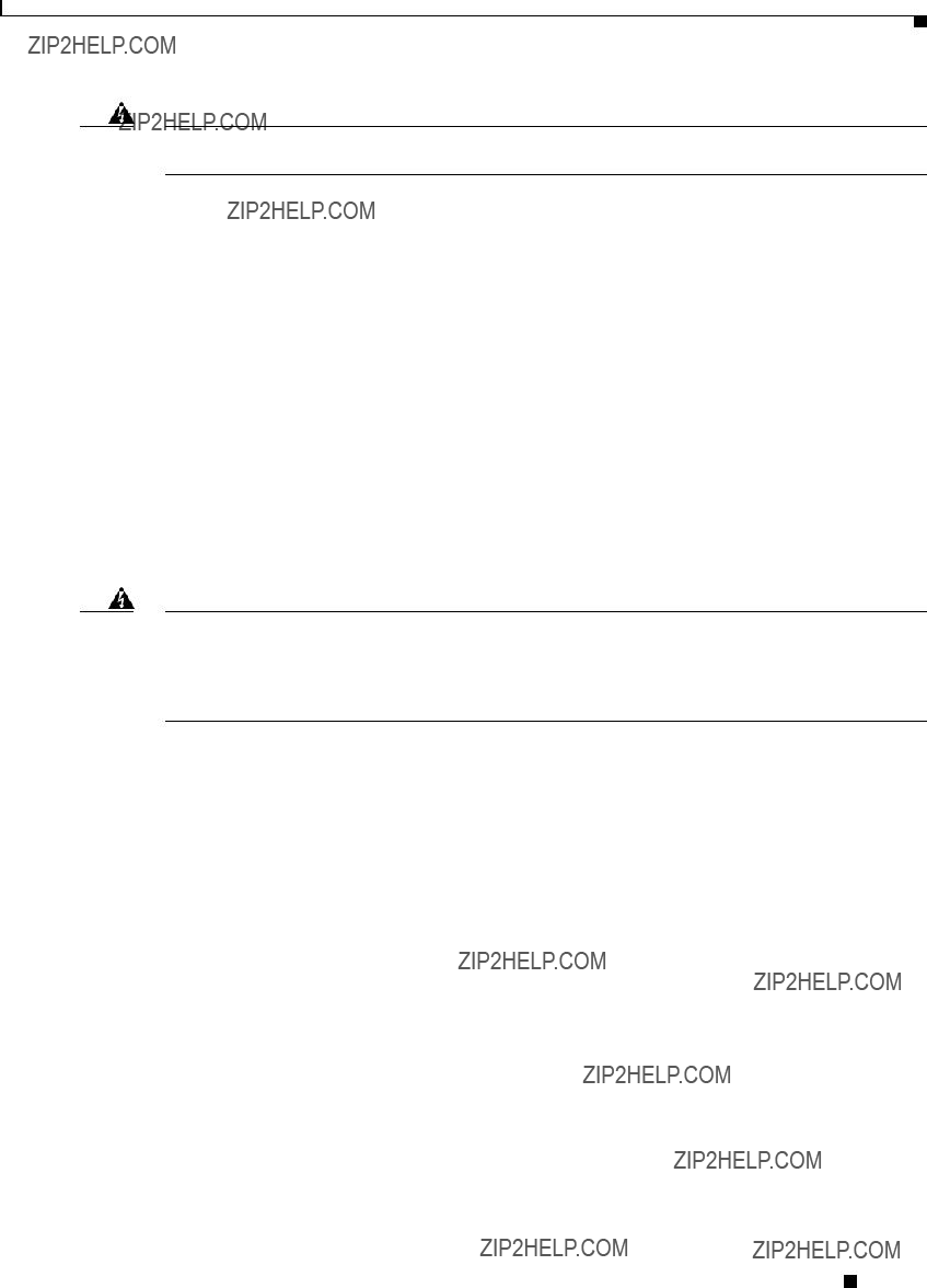
Bridge LEDs
Four LEDs are located on back of the housing to report installation and alignment conditions, bridge status, radio activity, and Ethernet activity (see Figure
Figure
6
The bridge LEDs are shown in Figure
???The install LED indicates that installation mode is activated. During installation mode, the other LEDs provide signal strength readings used for antenna alignment.
???The radio LED blinks green to indicate radio traffic activity. The light is normally off, but it blinks green whenever a packet is received or transmitted over the bridge radio link. This LED also provides signal strength readings during installation mode.
???The status LED signals bridge association status. Blinking green indicates that the bridge is not associated with another bridge. Steady green indicates that the bridge is associated with at least one other bridge. This LED also provides signal strength readings during installation mode.
Cisco Aironet 1400 Series Wireless Bridge Hardware Installation Guide.

Chapter 1 Overview
Network Configuration Examples
???The Ethernet LED signals Ethernet traffic. This LED blinks green when a packet is received or transmitted over the Ethernet infrastructure. The LED is off when the Ethernet link not working or the port is shutdown. This LED also provides signal strength readings during installation mode.
For additional information on the LEDs, refer to ???Checking the Bridge LEDs??? section on page
Receive Signal Strength Indicator Port
The bridge supports a receive signal strength indicator (RSSI) port for use in antenna alignment. The RSSI port produces a DC voltage proportional to the strength of the received radio signal. The highest voltage indicates the best antenna alignment position. The RSSI port is a female BNC connector located on the bottom of the bridge housing (see Figure
Note The RSSI port requires the use of a voltmeter and a cable with a male BNC connector.
Network Configuration Examples
This section describes the bridge???s role in three common wireless network configurations.
In a
Figure
88833
Cisco Aironet 1400 Series Wireless Bridge Hardware Installation Guide.
Chapter 1 Overview
Network Configuration Examples
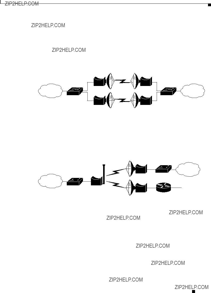
Port Aggregation or Redundancy Configuration
The port aggregation or redundancy configuration (Figure
Figure
88834
The
Figure
Bridge
Bridge
Bridge
 88835
88835
Cisco Aironet 1400 Series Wireless Bridge Hardware Installation Guide.
Chapter 1 Overview
Bridge Specifications
Bridge Specifications
The bridge, power injector, and power module specifications are listed in Table
Cisco Aironet 1400 Series Wireless Bridge Hardware Installation Guide.

Chapter 1 Overview
Bridge Specifications
Cisco Aironet 1400 Series Wireless Bridge Hardware Installation Guide.

Chapter 1 Overview
Bridge Specifications
Maximum Power Levels
Each regulatory region limits the equivalent isotropic radiated power (EIRP) that can be supported within their region. This restricts the bridge output power that can be used with the bridge antennas and affects the resulting operating range of the bridge (for additional information refer to Appendix C, ???Channels and Maximum Power Levels.???
Cisco Aironet 1400 Series Wireless Bridge Hardware Installation Guide.

C H A P T E R 2
Installation Overview
This chapter provides warnings, safety information, and information needed before you begin the installation of your bridge system. This chapter includes the following sections:
???Safety Information, page
???Unpacking the Bridge, page
???Before Beginning the Installation, page
???Installation Summary, page
Cisco Aironet 1400 Series Wireless Bridge Hardware Installation Guide.

Chapter 2 Installation Overview
Warnings
Warnings
Translated versions of the following safety warnings are provided in Appendix A, ???Translated Safety Warnings.???
Warning This warning symbol means danger. You are in a situation that could cause bodily injury. Before you work on any equipment, be aware of the hazards involved with electrical circuitry and be familiar with standard practices for preventing accidents. (To see translations of the warnings that appear in this publication, refer to the appendix ???Translated Safety Warnings.???)
Warning Only trained and qualified personnel should be allowed to install, replace, or service this equipment.
Warning Do not locate the antenna near overhead power lines or other electric light or power circuits, or where it can come into contact with such circuits. When installing the antenna, take extreme care not to come into contact with such circuits, as they may cause serious injury or death. For proper installation and grounding of the antenna, please refer to national and local codes (e.g. U.S.:NFPA 70, National Electrical Code, Article 810, in Canada: Canadian Electrical Code, Section 54).
Warning This product relies on the building???s installation for
120 VAC, 15A U.S. (240 VAC, 10A International)
Warning This equipment must be grounded. Never defeat the ground conductor or operate the equipment in the absence of a suitably installed ground conductor. Contact the appropriate electrical inspection authority or an electrician if you are uncertain that suitable grounding is available.
Warning Read the installation instructions before you connect the system to its power source.
Warning Do not work on the system or connect or disconnect cables during periods of lightning activity.
Warning Do not operate your wireless network device near unshielded blasting caps or in an explosive environment unless the device has been modified to be especially qualified for such use.
Warning In order to comply with radio frequency (RF) exposure limits, the antennas for this product should be positioned no less than 6.56 ft (2 m) from your body or nearby persons.
Cisco Aironet 1400 Series Wireless Bridge Hardware Installation Guide.
Chapter 2 Installation Overview
Safety Information
Warning This unit is intended for installation in restricted access areas. A restricted access area can be accessed only through the use of a special tool, lock and key, or other means of security.
Safety Information
Follow the guidelines in this section to ensure proper operation and safe use of the bridge.
FCC Safety Compliance Statement
The FCC, with its action in ET Docket
Safety Precautions
Warning Do not locate the antenna near overhead power lines or other electric light or power circuits, or where it can come into contact with such circuits. When installing the antenna, take extreme care not to come into contact with such circuits, as they may cause serious injury or death. For proper installation and grounding of the antenna, please refer to national and local codes (e.g. U.S.:NFPA 70, National Electrical Code, Article 810, in Canada: Canadian Electrical Code, Section 54).
Each year hundreds of people are killed or injured when attempting to install an antenna. In many of these cases, the victim was aware of the danger of electrocution, but did not take adequate steps to avoid the hazard.
For your safety, and to help you achieve a good installation, please read and follow these safety precautions. They may save your life!
1.If you are installing an antenna for the first time, for your own safety as well as others, seek professional assistance.
2.Select your installation site with safety, as well as performance in mind. Remember: electric power lines and phone lines look alike. For your safety, assume that any overhead line can kill you.
3.Call your electric power company. Tell them your plans and ask them to come look at your proposed installation. This is a small inconvenience considering your life is at stake.
4.Plan your installation carefully and completely before you begin. Successful raising of a mast or tower is largely a matter of coordination. Each person should be assigned to a specific task, and should know what to do and when to do it. One person should be in charge of the operation to issue instructions and watch for signs of trouble.
5.When installing your antenna, remember:
a.Do not use a metal ladder.
b.Do not work on a wet or windy day.
Cisco Aironet 1400 Series Wireless Bridge Hardware Installation Guide.

Chapter 2 Installation Overview
Safety Information
c.Do dress
6.If the assembly starts to drop, get away from it and let it fall. Remember, the antenna, mast, cable, and metal guy wires are all excellent conductors of electrical current. Even the slightest touch of any of these parts to a power line complete an electrical path through the antenna and the installer: you!
7.If any part of the antenna system should come in contact with a power line, don???t touch it or try to remove it yourself. Call your local power company. They will remove it safely.
If an accident should occur with the power lines call for qualified emergency help immediately.
Typical Bridge Installation Components
The bridge is designed to be installed in an outdoor environment, typically, on a tower or a tall building. A typical bridge installation diagram is shown in Figure
Figure
88836
Note Ground wires must comply with Sections 810 and 820 of the National Electrical Code and Section 54 of the Canadian Electrical Code.
Caution To ensure correct installation and grounding, install the bridge in compliance with your local and national electrical codes: National Fire Protection Association (NFPA) 70, National Electrical Code (U.S.); Canadian Electrical Code, Part I, CSA 22.1 (Canada); and if local or national electrical codes are not available, refer to IEC 364, Part 1 through 7 (other countries).
Cisco Aironet 1400 Series Wireless Bridge Hardware Installation Guide.
Chapter 2 Installation Overview
Installation Guidelines
Installation Guidelines
Because the bridge is a radio device, it is susceptible to common causes of interference that can reduce throughput and range. Follow these basic guidelines to ensure the best possible performance:
???Install the bridge in an area where structures, trees, or hills do not obstruct radio signals to and from the bridge.
???Install the bridge at a height sufficient to provide clear
Site Surveys
Every network application is a unique installation. Before installing multiple bridges, you should perform a site survey to determine the optimum use of networking components and to maximize range, coverage, and network performance.
Consider the following operating and environmental conditions when performing a site survey:
???Data
???Antenna type and
???Physical
???
Unpacking the Bridge
Note If you are unpacking an external antenna bridge, do not remove the foam block attached to the face of the bridge until the bridge is installed. The foam protects the antenna connector.
Follow these steps to unpack the bridge:
Step 1 Open the shipping container and carefully remove the contents.
Step 2 Return all packing materials to the shipping container and save it.
Step 3 Ensure that all items listed in the ???Package Contents??? section are included in the shipment. If any item is damaged or missing, notify your authorized Cisco sales representative.
Cisco Aironet 1400 Series Wireless Bridge Hardware Installation Guide.

Chapter 2 Installation Overview
Before Beginning the Installation
Package Contents
Each bridge package contains the following items:
???Bridge unit
???Power injector unit (with mounting screws and wall anchors)
???Power module and AC power cord (with mounting screws and wall anchors)
???Two
???Mounting kit and hardware
???
???Two tower clamps
???Four bolts, lock washers, and washers for securing the bridge brackets to the tower or mast bracket
???Four bolts and lock washers for securing the bridge brackets to the bridge
???Grounding block and mounting screws
???Ground lug for the bridge with screws
???Weatherproofing kit (consisting of Coax Seal and electrical joint compound)
???Quick Start Guide: Cisco Aironet 1400 Series Wireless Bridge
???Cisco Aironet 1400 Series Wireless Bridge Mounting Instructions
???Cisco product registration and Cisco documentation feedback cards
Before Beginning the Installation
Before you begin the installation process, please carefully review the following list of figures to become familiar with the system components, connectors, indicators, cables, system interconnection, and grounding:
???Bridge Installation diagram (Figure
???Power injector layout (Figure
???Grounding block (Figure
Cisco Aironet 1400 Series Wireless Bridge Hardware Installation Guide.

Chapter 2 Installation Overview
Before Beginning the Installation
Figure
1
1
Cisco Aironet 1400 Series Wireless Bridge Hardware Installation Guide.
Chapter 2 Installation Overview
Before Beginning the Installation
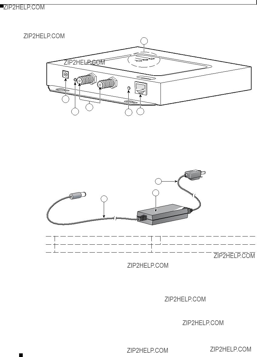
Figure
6
1
3
88809
3
2
1
88829
2 Power module
Cisco Aironet 1400 Series Wireless Bridge Hardware Installation Guide.

Chapter 2 Installation Overview
Installation Summary
Installation Summary
During the installation of the bridge, you will perform the following operations:
???Connect a
???Connect the
Tip You can connect the
Note You should securely tighten the cable connectors (15 to 20
???Connect a ground wire to the grounding block.
???Mount the bridge to the external tower or mast. For additional information, refer to the Cisco Aironet 1400 Series Wireless Bridge Mounting Instructions that shipped with your bridge.
???Connect a ground wire to the bridge (use the bridge ground lug).
???Connect the
Tip You can connect the
Note You should securely tighten the cable connectors (15 to 20
??? Connect the AC power cord to the
Cisco Aironet 1400 Series Wireless Bridge Hardware Installation Guide.

Chapter 2 Installation Overview
Installation Summary
???Connect the power module to the power injector and plug the AC cord into an AC power receptacle.
???Align the bridge antenna. For additional information, refer to the Cisco Aironet 1400 Series Wireless Bridge Mounting Instructions that shipped with your bridge.
???Configure basic settings (refer to Chapter 5, ???Configuring the Bridge for the First Time???).
???Seal all external connectors with special weather sealing material.
???Configure security and other bridge options. For additional information, refer to the Cisco Aironet 1400 Series Wireless Bridge Software Configuration Guide.
Cisco Aironet 1400 Series Wireless Bridge Hardware Installation Guide.

C H A P T E R 3
Mounting and Alignment Overview
This chapter provides an overview of bridge mounting and antenna alignment. The following sections are included in this chapter:
???Mounting the Bridge, page
???Mounting Hardware, page
???Aligning the Antenna Using LED Indications, page
???Aligning the Antenna Using the RSSI Voltage, page
Cisco Aironet 1400 Series Wireless Bridge Hardware Installation Guide.

Chapter 3 Mounting and Alignment Overview
Mounting the Bridge
Mounting the Bridge
Typically, the bridge is installed on a rooftop, mast, tower, wall, or a suitable flat surface. Each of these installations requires a different approach. This document provides a mounting overview. For detailed mounting instructions, refer to the Cisco Aironet 1400 Series Wireless Bridge Mounting Instructions that shipped with your bridge.
The bridge is available in two configurations:
???Integrated antenna bridge (with
???External antenna bridge (with antenna connector for use with an external antenna)
Note To meet regulatory restrictions, the external antenna bridge configuration and the external antenna must be professionally installed.
Personnel installing the bridge must understand wireless bridging techniques, antenna alignment and adjustment, and grounding methods. The integrated antenna configuration can be installed by an experienced IT professional.
Mounting Hardware
The bridge is shipped with the following mounting hardware:
???
???Fastener hardware (consisting of nuts, bolts, washers, and
The
1.Mount the two bridge brackets to the bridge with the support pins facing the sides of the bridge.
2.Mount the mast bracket to the tower or mast using the supplied
3.Suspend the bridge on the mast bracket using the bridge bracket support pins.
4.Secure the bridge brackets to the mast bracket using the supplied nuts, bolts, and washers (hand tighten).
5.Connect the
Note You should securely tighten the cable connectors (15 to 20
6.Connect the ground wire to the bridge.
7.Align the bridge and tighten the nuts and bolts.
Cisco Aironet 1400 Series Wireless Bridge Hardware Installation Guide.

Chapter 3 Mounting and Alignment Overview
Bridge LEDs
Bridge Brackets
The two bridge brackets mount on the back side of the bridge housing. Each bracket mounts on two screw posts on opposite ends of the unit. The support pin on the bridge bracket must be facing the side of the unit. These support pins are used to suspend the bridge in the notches on the mast mounting bracket until you secure the mounting bolts.
The bridge brackets must be positioned to obtain the correct antenna polarization that matches the remote antenna. The bridge housing contains an antenna polarization mark consisting of an arrow on the side of the housing. When the bridge is positioned so that the arrow is pointing up, the bridge antenna is vertically polarized. For horizontal polarization, the arrow should be pointing from left to right. All bridges must use the same antenna polarization for best operation.
Mast Bracket
The mast bracket attaches to a mast or tower support and is used to secure the bridge.The procedure for attaching the mounting bracket to the support depends on the pipe diameter, as shown in Table
Note The
Bridge LEDs
When you power up the bridge for the first time, it starts in a special installation mode. The LEDs indicate the startup status, operating mode, association status, and received signal strength. This information simplifies the process of activating the link and positioning the antenna from the bridge mounting location.
The LEDs are mounted on the back of the housing near the connectors (see Figure
Cisco Aironet 1400 Series Wireless Bridge Hardware Installation Guide.

Chapter 3 Mounting and Alignment Overview
Bridge LEDs
Figure
4
88818
When the bridge is initially
1. Preconfigured bridges search indefinitely.
Cisco Aironet 1400 Series Wireless Bridge Hardware Installation Guide.
Chapter 3 Mounting and Alignment Overview
Aligning the Antenna Using LED Indications
Use the Install LED to determine when the bridge successfully associates with a remote bridge and to verify its mode of operation. After association, the other three LEDs indicate signal strength (see Table
The startup and association sequence depends on the bridge configuration, which can be one of the following types:
???
???
Aligning the Antenna Using LED Indications
You can align the integrated antenna using LEDs after the bridge successfully associates with a remote bridge. In the installation mode before association to another bridge, the Install LED blinks amber. If the bridge associates to a root bridge, the Install LED turns continuous amber. If the bridge does not associate to a root bridge in the first 60 seconds, the Install LED blinks green to indicate beacons are being transmitted and the bridge is waiting for another
Note For the signal level (dBm), a smaller number represents a stronger signal because the signal level is given as a negative value.
1.Slow blinking rate of 1 blink/sec.
2.Medium blinking rate of 2 blinks/sec.
3.Fast blinking rate of 4 blinks/sec.
Cisco Aironet 1400 Series Wireless Bridge Hardware Installation Guide.

Chapter 3 Mounting and Alignment Overview
Aligning the Antenna Using the RSSI Voltage
When using LEDs to maximize the signal, adjust the antenna until as many LEDs as possible are turned on and the rest are blinking as fast as possible.
Aligning the Antenna Using the RSSI Voltage
The RSSI port produces a DC voltage that is proportional to the received signal level. The RSSI voltage is available whenever a signal is present, regardless of the bridge mode (installation or normal), association status, or pre configuration role setting. In Install mode, the RSSI voltage provides an instantaneous reading as you move the antenna. In Normal mode, the RSSI reading has a delay, so you must stop moving the antenna and wait before taking your reading. The RSSI port is a female BNC connector on the bridge housing (see Figure
The RSSI voltage increases linearly with signal level as shown in Table
Note A larger RSSI voltage reading indicates a stronger signal.
The voltage varies from 0 to 2.7 volts for signals between
Cisco Aironet 1400 Series Wireless Bridge Hardware Installation Guide.

C H A P T E R 4
Stacking Bridges
This chapter describes how to install stacked bridges for increased bandwidth and how to verify their isolation. This chapter contains the following topics:
???Choosing a Second Mounting Location, page
???Installing the Stacked Bridges, page
???Verifying Isolation, page
Cisco Aironet 1400 Series Wireless Bridge Hardware Installation Guide.

Chapter 4 Stacking Bridges
Overview
Overview
You can double the throughput, or create a standby link, by stacking two bridges. A stacked installation consists of two bridge systems installed at the same physical location. For detailed mounting instructions refer to the Cisco Aironet 1400 Series Wireless Bridge Mounting Instructions that shipped with your bridge.
Choosing a Second Mounting Location
You can mount the second bridge system in the same general location as the first as long as you separate the antennas by at least 8 ft (2.44 m). For example, in a
Interference path
95008

Chapter 4 Stacking Bridges
Verifying Isolation
Step 4 At each site location, temporarily install the second link 2 bridge, positioning the antenna toward the intended location of the corresponding link 2 remote antenna.
Note You can improve system isolation by using different polarizations for the two local antennas. For example, if the link 1 system has vertical polarization, assemble the link 2 system for horizontal polarization.
Verifying Isolation
Isolation measurements are valid only if the link 1 bridges are operating at maximum power. By default, the bridge operates at maximum power.
To verify signal isolation, refer to Figure
Step 1 Ensure that the link 1 bridges are operating at full power and bridge A is configured as the root bridge.
Step 2 At Site 1, measure the isolation between bridges A and B:
a.Activate the link 2 bridge (bridge B) as a
b.Connect a voltmeter to the RSSI port of bridge B, and verify that the voltage is 1.95 V
c.Slowly rotate the bridge B antenna a few degrees to the left and to the right and verify that the RSSI level does not rapidly spike above 1.95 V. If the voltage peaks above 1.95 V, move the bridge farther away and repeat this step.
Step 3 Go to the remote Site 2 location to measure the isolation between bridges A and D:
a.Activate the link 2 bridge (bridge D) as a
b.Connect a voltmeter to the RSSI port of bridge D and align the bridge D antenna with bridge A so that the RSSI voltage is maximized.
c.When the antennas are fully aligned, if the RSSI voltage level is greater than 1.95 V, the bridge sites are very close. Reduce the output power on all bridges at both sites (bridges A, B, C, and D) to 12 dBm.
d.If you are still unable to reduce the RSSI voltage level to 1.95 V, change the polarization of the link 2 bridges (bridges B and D). For example; change the antenna polarization from vertical to horizontal.
Step 4 At Site 2, measure the isolation between bridge C and D by following these steps:
a.Turn off bridge A for this measurement.
b.Activate the link 2 bridge (bridge D) as a
c.Connect a voltmeter to the RSSI port of bridge D and verify that the voltage is 1.95 V
Cisco Aironet 1400 Series Wireless Bridge Hardware Installation Guide.

Chapter 4 Stacking Bridges
Verifying Isolation
d.Slowly rotate the antenna of bridge D a few degrees to the left and to the right and verify that the RSSI level does not rapidly spike above 1.95 V. If the voltage peaks above 1.95 V, move the bridge farther away and repeat this step.
Step 5 After you verify the isolation of the second bridge link, you must properly set the root and
Cisco Aironet 1400 Series Wireless Bridge Hardware Installation Guide.

C H A P T E R 5
Configuring the Bridge for the First Time
This chapter describes how to configure basic settings on your bridge for the first time. The contents of this chapter are similar to the instructions in the quick start guide that shipped with your bridge. You can configure all the settings described in this chapter using the
This chapter contains these sections:
???Obtaining and Assigning an IP Address, page
???Connecting to the Bridge Locally, page
???Assigning Basic Settings, page
???Using the IP Setup Utility, page
???Assigning an IP Address Using the CLI, page
???Using a Telnet Session to Access the CLI, page
Cisco Aironet 1400 Series Wireless Bridge Hardware Installation Guide.
Chapter 5 Configuring the Bridge for the First Time
Before You Start
Before You Start
Before you install the bridge, make sure you are using a computer connected to the same network as the bridge, and obtain the following information:
???From your network system administrator:
???A system name
???The
???If not connected to a DHCP server, a unique IP address for your bridge (such as 172.17.255.115)
???If the bridge is not on the same subnet as your PC, a default gateway address and subnet mask
???A Simple Network Management Protocol (SNMP) community name and the SNMP file attribute (if SNMP is in use)
???If you use IPSU to find or assign the bridge IP address, the MAC address from the label on the bottom of the bridge (such as 00164625854c)
Resetting the Bridge to Default Settings
If you need to start over during the initial setup process, follow these steps to reset the bridge to factory default settings using the power injector???s Mode button:
Step 1 Disconnect the power jack from the power injector.
Step 2 Press and hold the power injector???s MODE button while you reconnect the power jack.
Step 3 Hold the MODE button until the Status LED turns amber (approximately 1 to 3 seconds) and wait until the bridge boots up (Status LED turns green). All bridge settings return to factory defaults.
You can also use the
Step 1 Open your Internet browser. You must use Microsoft Internet Explorer (version 5.x or later) or Netscape Navigator (version 4.x).
Step 2 Enter the bridge???s IP address in the browser address line and press Enter. An Enter Network Password window appears.
Step 3 Enter your username in the User Name field. The default username is Cisco.
Step 4 Enter the bridge password in the Password field and press Enter. The default password is Cisco. The Summary Status page appears.
Step 5 Click System Software and the System Software screen appears.
Step 6 Click System Configuration and the System Configuration screen appears.
Step 7 Click Default.
Cisco Aironet 1400 Series Wireless Bridge Hardware Installation Guide.

Chapter 5 Configuring the Bridge for the First Time
Obtaining and Assigning an IP Address
Note If the bridge is configured with a static IP address, the IP address is not changed.
Obtaining and Assigning an IP Address
To browse to the bridge???s Express Setup page, you must either obtain or assign the bridge???s IP address using one of the following methods:
???Use default address 10.0.0.1 when you connect to the bridge locally. For detailed instructions, see the ???Connecting to the Bridge Locally??? section on page
???Use a DHCP server (if available) to automatically assign an IP address. You can find the
???Provide your organization???s network administrator with your bridge???s Media Access Control (MAC) address. Your network administrator will query the DHCP server using the MAC address to identify the IP address. The bridge???s MAC address is on label attached to the bottom of the bridge.
???Use the Cisco IP Setup Utility (IPSU) to identify the assigned address. You can also use IPSU to assign an IP address to the bridge if it did not receive an IP address from the DHCP server. IPSU runs on most Microsoft Windows operating systems: Windows 9x, 2000, Me, NT, and XP.
You can download IPSU from the Software Center on Cisco.com. For additional information refer to the ???Obtaining and Installing IPSU??? section on page
Connecting to the Bridge Locally
If you need to configure the bridge locally (without connecting the bridge???s power injector to a wired LAN), you can connect a PC to the power injector???s Ethernet port using a Category 5 Ethernet cable. You can use a local connection to the Ethernet port much as you would use a serial port connection.
Note You do not need a special crossover cable to connect your PC to the bridge???s power injector; you can use either a
If the bridge is configured with default values and not connected to a DHCP server or cannot obtain an IP address, it defaults to IP address 10.0.0.1 and becomes a
The
Caution When a bridge with default settings is connected on a wired LAN and does not receive an IP address from a DHCP server, the bridge provides an IP address to any DHCP requests it receives.
Cisco Aironet 1400 Series Wireless Bridge Hardware Installation Guide.

Chapter 5 Configuring the Bridge for the First Time
Assigning Basic Settings
Follow these steps to connect to the bridge locally:
Step 1 Make sure that the PC you intend to use is configured to obtain an IP address automatically, or manually assign it an IP address from 10.0.0.31 to 10.0.0.40. Connect your PC to the power injector using a Category 5 Ethernet cable. You can use either a crossover cable or a
Note When you connect your PC to the bridge???s power injector or reconnect your PC to the wired LAN, you might need to release and renew the IP address on the PC. On most PCs, you can perform a release and renew by rebooting your PC or by entering ipconfig /release and ipconfig /renew commands in a command prompt window. Consult your PC operating instructions for detailed instructions.
Step 2 Power up the power injector.
Step 3 Follow the steps in the ???Assigning Basic Settings??? section on page
Step 4 After configuring the bridge, remove the Ethernet cable from your PC and connect the power injector to your wired LAN.
Assigning Basic Settings
After you determine or assign the bridge???s IP address, you can browse to the bridge???s Express Setup page and perform an initial configuration. Follow these steps:
Step 1 Open your Internet browser. You must use Microsoft Internet Explorer (version 5.x or later) or Netscape Navigator (version 4.x).
Step 2 Enter the bridge???s IP address in the browser address line and press Enter. An Enter Network Password screen appears.
Step 3 Press Tab to bypass the Username field and advance to the Password field.
Step 4 Enter the
Cisco Aironet 1400 Series Wireless Bridge Hardware Installation Guide.
Chapter 5 Configuring the Bridge for the First Time
Assigning Basic Settings
Figure
Step 5 Click Express Setup. The Express Setup screen appears. Figure
Figure
Cisco Aironet 1400 Series Wireless Bridge Hardware Installation Guide.
Chapter 5 Configuring the Bridge for the First Time
Assigning Basic Settings
Step 6 Enter the configuration settings you obtained from your system administrator. The configurable settings include:
???System
???Configuration Server
???
Note When DHCP is enabled, the IP Address, Subnet Mask, and Default Gateway fields indicate
Negotiated by DHCP
???Static
???IP
Note If the bridge???s IP address changes while you are configuring the bridge using the
???IP Subnet
???Default
???SNMP
???
???
???Radio Service Set ID
???Broadcast SSID in
???
???
Cisco Aironet 1400 Series Wireless Bridge Hardware Installation Guide.
Chapter 5 Configuring the Bridge for the First Time
Assigning Basic Settings
???Role in Radio
???Install
You can also
???
???
Note When initially powered up, the bridge is configured in Install mode with automatic detection activated.
???Optimize Radio Network
???
???
???
???
page. Clicking Custom takes you to the Network Interfaces:
Step 7 Click Apply to save your settings. If you changed the IP address, you lose your connection to the bridge. Browse to the new IP address to reconnect to the bridge.
Note You can restore the bridge to its factory defaults by unplugging the power injector???s power jack and plugging it back in while holding down the Mode button for a few seconds, or until the Status LED turns amber.
Cisco Aironet 1400 Series Wireless Bridge Hardware Installation Guide.
Chapter 5 Configuring the Bridge for the First Time
What To Do Next
Default Settings on the Express Setup Page
Table
Table
1.During Install Mode, the SSID is autoinstall.
2.After a static IP address is assigned or the role is changed from Install, the SSID is tsunami.
What To Do Next
After your bridge has basic settings, you need to complete your bridge???s configuration. You might need to adjust the output power level and other network and security settings.
Output Power Level
Your bridge???s output power level might require adjustment under the following conditions:
???The bridge???s output power level must be reduced when using an external dish antenna or when using the integrated antenna in a multipoint configuration (refer to ???Channels and Maximum Power Levels??? section on page
???When bridges are installed less than 328 ft (100 m) apart, you should reduce their output power to avoid overloading the bridge???s receivers.
To configure your bridge???s output power level, refer to the Cisco Aironet 1400 Series Wireless Bridge
Software Configuration Guide.
Cisco Aironet 1400 Series Wireless Bridge Hardware Installation Guide.

Chapter 5 Configuring the Bridge for the First Time
Using the IP Setup Utility
Protecting Your Wireless LAN
To prevent unauthorized access to your network, you must configure security settings. Because the bridge is a radio device, the bridge communicates beyond the physical boundaries of your building. Refer to the Cisco Aironet 1400 Series Wireless Bridge Software Configuration Guide to configure security features to protect your network from intruders:
???Unique SSIDs that are not broadcast in the bridge beacon
???WEP and additional WEP features, such as TKIP and broadcast key rotation
???Dynamic WEP and EAP authentication
Using the IP Setup Utility
IPSU enables you to find the bridge???s IP address when it has been assigned by a DHCP server. You can also use IPSU to set the bridge???s IP address and SSID if they have not been changed from the default settings.
Note IPSU can be used only on the following operating systems: Windows 95, 98, NT, 2000, ME, or XP.
The sections below explain how to install the utility, how to use it to find the bridge???s IP address, and how to use it to set the IP address and the SSID.
Obtaining and Installing IPSU
IPSU is available on the Cisco web site. Follow these steps to obtain and install IPSU:
Step 1 Use your web browser to go to the Cisco Software Center at the following URL:
Step 2 Select Option #1: Aironet Wireless Software Selector.
Step 3 For the Product Type, select Wireless Bridge and click Submit.
Step 4 Select 1400 Series for the model number and click Submit.
Step 5 Select Current Release (Recommended) and click Submit.
Step 6 Under Utilities, select IPSUvxxxxxx.exe.
Step 7 On the Encryption Authorization Form, enter the requested information, read the encryption information, and check the boxes that apply. Click Submit.
Step 8 Read and accept the terms and conditions of the Software License Agreement.
Step 9 Select the IPSU file again to download it.
Step 10 Save the file to a temporary directory on your hard drive and then exit the Internet browser.
Step 11
Step 12
The IPSU icon appears on your computer desktop.
Cisco Aironet 1400 Series Wireless Bridge Hardware Installation Guide.

Chapter 5 Configuring the Bridge for the First Time
Using the IP Setup Utility
Using IPSU to Find the Bridge???s IP Address
If your bridge receives an IP address from a DHCP server, you can use IPSU to find its IP address. Because IPSU sends a
Step 1
Figure
Step 2 When the utility window opens, make sure the Get IP address radio button in the Function box is selected.
Step 3 Enter the bridge???s MAC address in the Device MAC ID field. The bridge???s MAC address is printed on the label on the bottom of the unit. It should contain six pairs of hexadecimal digits. Your bridge???s MAC address might look like the following example:
000164xxxxxx
Note The MAC address field is not case sensitive.
Step 4 Click Get IP Address.
Step 5 When the bridge???s IP address appears in the IP Address field, write it down.
If IPSU reports that the IP address is 10.0.0.1, the default IP address, the bridge did not receive a
Cisco Aironet 1400 Series Wireless Bridge Hardware Installation Guide.

Chapter 5 Configuring the Bridge for the First Time
Using the IP Setup Utility
Using IPSU to Set the Bridge???s IP Address and SSID
You can use IPSU to change the default IP address (10.0.0.1) of the bridge. You can also set the bridge???s SSID at the same time.
Note The computer you use to assign an IP address to the bridge must have an IP address in the same subnet as the bridge (10.0.0.x).
Note IPSU can change the bridge???s IP address and SSID only from their default settings. After the IP address and SSID are changed, IPSU cannot change them again.
Follow these steps to assign an IP address and an SSID to the bridge:
Step 1
Step 2 Click the Set Parameters radio button in the Function box (see Figure
Figure
Step 3 Enter the bridge???s MAC address in the Device MAC ID field. The bridge???s MAC address is printed on the label on the bottom of the unit. It should contain six pairs of hexadecimal digits. Your bridge???s MAC address might look like this example:
004096xxxxxx
Note The MAC address field is not case sensitive.
Step 4 Enter the IP address you want to assign to the bridge in the IP Address field.
Step 5 Enter the SSID you want to assign to the bridge in the SSID field.
Note You cannot set the SSID without also setting the IP address. However, you can set the IP address without setting the SSID.
Cisco Aironet 1400 Series Wireless Bridge Hardware Installation Guide.

Chapter 5 Configuring the Bridge for the First Time
Assigning an IP Address Using the CLI
Step 6 Click Set Parameters to change the bridge???s IP address and SSID settings.
Step 7 Click Exit to exit IPSU.
Assigning an IP Address Using the CLI
When you connect the bridge to the wired LAN, the bridge links to the network using a bridge virtual interface (BVI) that it creates automatically. Instead of tracking separate IP addresses for the bridge???s Ethernet and radio ports, the network uses the BVI.
When you assign an IP address to the bridge using the CLI, you must assign the address to the BVI. Beginning in privileged EXEC mode, follow these steps to assign an IP address to the bridge???s BVI:
Using a Telnet Session to Access the CLI
Follow these steps to access the CLI using a Telnet session. These steps are for a PC running Microsoft Windows with a Telnet terminal application. Check your PC operating instructions for detailed instructions for your operating system.
Step 1 Select Start > Programs > Accessories > Telnet.
If Telnet is not listed in your Accessories menu, select Start > Run, type Telnet in the entry field, and press Enter.
Step 2 When the Telnet window appears, click Connect and select Remote System.
Note In Windows 2000, the Telnet window does not contain
Step 3 In the Host Name field, type the bridge???s IP address and click Connect.
Cisco Aironet 1400 Series Wireless Bridge Hardware Installation Guide.

C H A P T E R 6
Troubleshooting
This chapter provides troubleshooting procedures for basic problems with the bridge. For the most
Sections in this chapter include:
???Checking the Bridge LEDs, page
???Power Injector LEDs, page
???Checking Basic Configuration Settings, page
???Antenna Alignment, page
???Resetting to the Default Configuration, page
???Reloading the Bridge Image, page
Cisco Aironet 1400 Series Wireless Bridge Hardware Installation Guide.

Chapter 6 Troubleshooting
Checking the Bridge LEDs
Checking the Bridge LEDs
If your bridge is not associating with the remote bridge, check the four LEDs on the back panel. You can use them to quickly assess the unit???s status. For information on using the LEDs during the installation and alignment of the bridge antenna, refer to the ???Bridge LEDs??? section on page
Figure
4
88818
Bridge Normal Mode LED Indications
During bridge operation the LEDs provide status information as shown in Table
Table
Chapter 6 Troubleshooting
Checking the Bridge LEDs
Cisco Aironet 1400 Series Wireless Bridge Hardware Installation Guide.

Chapter 6 Troubleshooting
Power Injector LEDs
The bridge uses a blinking code to identify various error conditions. The code sequence uses a
Power Injector LEDs
The power injector contains three LEDs to provide status information on the wired Ethernet link, the bridge Ethernet link, and the bridge status. When the power injector is powered up, it sends a constant discovery tone on the
When power is applied to the bridge, the bridge activates the bootloader and begins the POST operations. The bridge begins to load the IOS image when the Post operations are successfully completed. Upon successfully loading the IOS image, the bridge initializes and tests the radio.
Cisco Aironet 1400 Series Wireless Bridge Hardware Installation Guide.

Chapter 6 Troubleshooting
Power Injector LEDs
The power injector LEDs are shown in Figure
Figure
7
6 8
1
3
88820

Chapter 6 Troubleshooting
Checking Power
Checking Power
You can verify the availability of power to the bridge by checking the power injector LEDs (see Figure
???Power LED
???Green color indicates 48 VDC is available to the power injector (see Figure
???Off indicates 48 VDC is not available to the power
???Uplink Activity LED
???Green or blinking green color indicates the bridge is operating.
Cisco Aironet 1400 Series Wireless Bridge Hardware Installation Guide.

Chapter 6 Troubleshooting
Checking Basic Configuration Settings
???Off indicates that the power
???Amber color indicates that an internal power injector
???Status LED
???Green or blinking green color indicates that the bridge is operating.
???Blinking amber color indicates that the bridge has not been detected by the power injector and that power is not being supplied to the
Checking Basic Configuration Settings
Mismatched basic settings are the most common causes of lost wireless connectivity. If the bridge does not associate with a remote bridge, check the following areas.
SSID
To associate, all bridges must use the same SSID. The bridge installation mode SSID is autoinstall and the normal mode default SSID is tsunami. You should verify that the SSID value shown on the Express Setup page is the same for all bridges. You should also verify that the bridges are configured for the proper network role; only one bridge can be configured as the root bridge.
Security Settings
Remote bridges attempting to authenticate to your bridge must support the same security options configured in the bridge, such as WEP, EAP or LEAP, MAC address authentication, Message Integrity Check (MIC), WEP key hashing, and 802.1X protocol versions.
If a
Cisco Aironet 1400 Series Wireless Bridge Hardware Installation Guide.

Chapter 6 Troubleshooting
Antenna Alignment
Antenna Alignment
If your
Note To meet regulatory restrictions, the external antenna bridge configuration and the external antenna must be professionally installed.
For detailed alignment instructions, refer to the Cisco Aironet 1400 Series Wireless Bridge Mounting Instructions that shipped with your bridge.
Resetting to the Default Configuration
If you forget the password that allows you to configure the bridge, you may need to completely reset the configuration. You can use the MODE button on the power injector or the
Note The following steps reset all configuration settings to factory defaults, including passwords, WEP keys, the IP address, and the SSID.
Using the MODE Button
Follow these steps to delete the current configuration and return all bridge settings to factory defaults using the MODE button:
Step 1 Disconnect the power jack on the power injector.
Step 2 Press and hold the MODE button while you reconnect power to the power injector.
Step 3 Hold the MODE button until the Status LED turns amber (approximately 3 seconds).
Step 4 After the bridge reboots, you must reconfigure the bridge by using the Web browser interface, the Telnet interface, or IOS commands.
Note The bridge is configured with the factory default values including the IP address (set to receive an IP address using DHCP). To obtain the bridge???s new IP address, refer to the ???Using the IP Setup Utility??? section on page
Cisco Aironet 1400 Series Wireless Bridge Hardware Installation Guide.
Chapter 6 Troubleshooting
Reloading the Bridge Image
Using the Web Browser Interface
Follow the steps below to delete the current configuration and return all bridge settings to the factory defaults using the web browser interface.
Step 1 Open your Internet browser. You must use Microsoft Internet Explorer (version 5.x or later) or Netscape Navigator (version 4.x).
Step 2 Enter the bridge???s IP address in the browser address line and press Enter. An Enter Network Password screen appears.
Step 3 Enter your username in the User Name field.
Step 4 Enter the bridge password in the Password field and press Enter. The Summary Status page appears.
Step 5 Click System Software and the System Software screen appears.
Step 6 Click System Configuration and the System Configuration screen appears.
Step 7 Click Default.
Note If the bridge is configured with a static IP address, the IP address does not change.
Step 8 After the bridge reboots, you must reconfigure the bridge by using the Web browser interface, the Telnet interface, or IOS commands.
Reloading the Bridge Image
If your bridge has a firmware failure, you must reload the complete bridge image file using the Web browser interface or by pressing and holding the MODE button for around 30 seconds. You can use the browser interface if the bridge firmware is still fully operational and you want to upgrade the firmware image. However, you can use the MODE button when the bridge has a corrupt firmware image.
Using the MODE button
You can use the MODE button on the bridge to reload the bridge image file from an active Trivial File Transfer Protocol (TFTP) server on a PC connected directly to the power injector Ethernet port.
Note If your bridge experiences a firmware failure or a corrupt firmware image, indicated by three red LEDs, you must reload the image from a directly connected PC with a TFTP server.
Note This process resets all configuration settings to factory defaults, including passwords, WEP keys, the bridge IP address, and SSIDs.
Follow the steps below to reload the bridge image file:
Step 1 The PC you intend to use must be configured with a static IP address in the range of 10.0.0.2 to 10.0.0.30.
Cisco Aironet 1400 Series Wireless Bridge Hardware Installation Guide.

Chapter 6 Troubleshooting
Reloading the Bridge Image
Step 2 Make sure the PC contains the bridge image file
Step 3 Connect the PC to the bridge using a Category 5 Ethernet cable.
Step 4 Disconnect the power jack from the power injector.
Step 5 Press and hold the MODE button while you reconnect power to the power injector.
Step 6 Hold the MODE button until the status LED turns red (approximately 20 to 30 seconds).
Step 7 Wait until the bridge reboots as indicated by all LEDs turning green followed by the Status LED blinking green.
Step 8 After the bridge reboots, you must reconfigure the bridge by using the Web interface, the Telnet interface, or IOS commands.
Note The bridge is configured with the factory default values including the IP address (set to receive an IP address using DHCP). To obtain the bridge???s new IP address, refer to the ???Using the IP Setup Utility??? section on page
Web Browser Interface
You can also use the Web browser interface to reload the bridge image file. The Web browser interface supports loading the image file using HTTP or TFTP interfaces.
Note Your bridge configuration is not changed when using the browser to reload the image file.
Browser HTTP Interface
The HTTP interface enables you to browse to the bridge image file on your PC and download the image to the bridge. Follow the instructions below to use the HTTP interface:
Step 1 Open your Internet browser. You must use Microsoft Internet Explorer (version 5.x or later) or Netscape Navigator (version 4.x).
Step 2 Enter the bridge???s IP address in the browser address line and press Enter. An Enter Network Password screen appears.
Step 3 Enter your username in the User Name field.
Step 4 Enter the bridge password in the Password field and press Enter. The Summary Status page appears.
Step 5 Click the System Software tab and then click Software Upgrade. The HTTP Upgrade screen appears.
Step 6 Click Browse to locate the image file on your PC.
Step 7 Click Upload.
For additional information, click the Help icon on the Software Upgrade screen.
Cisco Aironet 1400 Series Wireless Bridge Hardware Installation Guide.

Chapter 6 Troubleshooting
Reloading the Bridge Image
Browser TFTP Interface
The TFTP interface enables you to use a TFTP server on a network device to load the bridge image file. Follow the instructions below to use a TFTP server:
Step 1 Open your Internet browser. You must use Microsoft Internet Explorer (version 5.x or later) or Netscape Navigator (version 4.x).
Step 2 Enter the bridge???s IP address in the browser address line and press Enter. An Enter Network Password screen appears.
Step 3 Enter your username in the User Name field.
Step 4 Enter the bridge password in the Password field and press Enter. The Summary Status page appears.
Step 5 Click System Software and then click Software Upgrade. The HTTP Upgrade screen appears.
Step 6 Click TFTP Upgrade.
Step 7 Enter the IP address for the TFTP server in the TFTP Server field.
Step 8 Enter the filename for the bridge image file
Step 9 Click Upload.
For additional information click the Help icon on the Software Upgrade screen.
Obtaining the Bridge Image File
You can obtain the bridge image file from the Cisco.com software center by following these steps:
Step 1 Use your web browser to go to the Cisco Software Center at the following URL:
Step 2 Select Option #1: Aironet Wireless Software Selector.
Step 3 For the Product Type, select Wireless Bridge and click Submit.
Step 4 Select 1400 Series for the model number and click Submit.
Step 5 Select Current Release (Recommended) and click Submit.
Step 6 Select
Step 7 On the Encryption Authorization Form, enter the requested information, read the encryption information, and check the boxes that apply. Click Submit.
Step 8 Read and accept the terms and conditions of the Software License Agreement.
Step 9 Select the bridge image file again to download it.
Step 10 Save the file to a directory on your hard drive and then exit the Internet browser.
Cisco Aironet 1400 Series Wireless Bridge Hardware Installation Guide.

Chapter 6 Troubleshooting
Reloading the Bridge Image
Obtaining the TFTP Server Software
You can download TFTP server software from several web sites. Cisco recommends the shareware TFTP utility available at this URL:
Follow the instructions on the website for installing and using the utility.
Cisco Aironet 1400 Series Wireless Bridge Hardware Installation Guide.
A P P E N D I X A
Translated Safety Warnings
This appendix provides translations of the safety warnings that appear in this publication. These translated warnings apply to other documents in which they appear in English. The following safety warnings appear in this appendix:
???Installation Warning, page
???Installation and Grounding Warning, page
???Circuit Breaker Warning, page
???Ground Conductor Warning, page
???Installation Warning, page
???Lightning Activity Warning, page
???Explosive Device Proximity Warning, page
???Radio Frequency Exposure Limits, page
???Restricted Area Warning, page
Cisco Aironet 1400 Series Wireless Bridge Hardware Installation Guide.
Appendix A Translated Safety Warnings
Warning Definition
Warning Definition
Warning This warning symbol means danger. You are in a situation that could cause bodily injury. Before you work on any equipment, be aware of the hazards involved with electrical circuitry and be familiar with standard practices for preventing accidents. (To see translations of the warnings that appear in this publication, refer to the appendix ???Translated Safety Warnings.???)
Waarschuwing Dit waarschuwingssymbool betekent gevaar. U verkeert in een situatie die lichamelijk letsel kan veroorzaken. Voordat u aan enige apparatuur gaat werken, dient u zich bewust te zijn van de bij elektrische schakelingen betrokken risico???s en dient u op de hoogte te zijn van standaard maatregelen om ongelukken te voorkomen. (Voor vertalingen van de waarschuwingen die in deze publicatie verschijnen, kunt u het aanhangsel ???Translated Safety Warnings??? (Vertalingen van veiligheidsvoorschriften) raadplegen.)
Varoitus T??m?? varoitusmerkki merkitsee vaaraa. Olet tilanteessa, joka voi johtaa ruumiinvammaan. Ennen kuin ty??skentelet mink????n laitteiston parissa, ota selv???? s??hk??kytkent??ihin liittyvist?? vaaroista ja tavanomaisista onnettomuuksien ehk??isykeinoista. (T??ss?? julkaisussa esiintyvien varoitusten k????nn??kset l??yd??t liitteest?? "Translated Safety Warnings" (k????nnetyt turvallisuutta koskevat varoitukset).)
Attention Ce symbole d???avertissement indique un danger. Vous vous trouvez dans une situation pouvant en- tra??ner des blessures. Avant d???acc??der ?? cet ??quipement, soyez conscient des dangers pos??s par les circuits ??lectriques et
Warnung Dieses Warnsymbol bedeutet Gefahr. Sie befinden sich in einer Situation, die zu einer K??rperver- letzung f??hren k??nnte. Bevor Sie mit der Arbeit an irgendeinem Ger??t beginnen, seien Sie sich der mit elektrischen Stromkreisen verbundenen Gefahren und der Standardpraktiken zur Vermeidung von Unf??llen bewu??t. (??bersetzungen der in dieser Ver??ffentlichung enthaltenen Warnhinweise finden Sie im Anhang mit dem Titel ???Translated Safety Warnings??? (??bersetzung der Warnhin- weise).)
Avvertenza Questo simbolo di avvertenza indica un pericolo. Si ?? in una situazione che pu?? causare infortuni. Prima di lavorare su qualsiasi apparecchiatura, occorre conoscere i pericoli relativi ai circuiti elettrici ed essere al corrente delle pratiche standard per la prevenzione di incidenti. La traduz- ione delle avvertenze riportate in questa pubblicazione si trova nell???appendice, ???Translated Safe- ty Warnings??? (Traduzione delle avvertenze di sicurezza).
Advarsel Dette varselsymbolet betyr fare. Du befinner deg i en situasjon som kan f??re til personskade. F??r du utf??rer arbeid p?? utstyr, m?? du v??re oppmerksom p?? de faremomentene som elektriske kretser inneb??rer, samt gj??re deg kjent med vanlig praksis n??r det gjelder ?? unng?? ulykker. (Hvis du vil se oversettelser av de advarslene som finnes i denne publikasjonen, kan du se i vedlegget "Trans- lated Safety Warnings" [Oversatte sikkerhetsadvarsler].)
Aviso Este s??mbolo de aviso indica perigo.
Cisco Aironet 1400 Series Wireless Bridge Hardware Installation Guide.

Appendix A Translated Safety Warnings
Installation Warning
??Advertencia! Este s??mbolo de aviso significa peligro. Existe riesgo para su integridad f??sica. Antes de manipu- lar cualquier equipo, considerar los riesgos que entra??a la corriente el??ctrica y familiarizarse con los procedimientos est??ndar de prevenci??n de accidentes. (Para ver traducciones de las ad- vertencias que aparecen en esta publicaci??n, consultar el ap??ndice titulado ???Translated Safety Warnings.???)
Varning! Denna varningssymbol signalerar fara. Du befinner dig i en situation som kan leda till personska- da. Innan du utf??r arbete p?? n??gon utrustning m??ste du vara medveten om farorna med elkretsar och k??nna till vanligt f??rfarande f??r att f??rebygga skador. (Se f??rklaringar av de varningar som f??rekommer i denna publikation i appendix "Translated Safety Warnings" [??versatta s??kerhets- varningar].)
Installation Warning
Warning Only trained and qualified personnel should be allowed to install, replace, or service this equipment.
Waarschuwing Deze apparatuur mag alleen worden ge??nstalleerd, vervangen of hersteld door bevoegd geschoold personeel.
Varoitus T??m??n laitteen saa asentaa, vaihtaa tai huoltaa ainoastaan koulutettu ja laitteen tunteva henkil??kunta.
Attention Il est vivement recommand?? de confier l'installation, le remplacement et la maintenance de ces ??quipements ?? des personnels qualifi??s et exp??riment??s.
Warnung Das Installieren, Ersetzen oder Bedienen dieser Ausr??stung sollte nur geschultem, qualifiziertem Personal gestattet werden.
Figyelem! A berendez??st csak szakk??pzett szem??lyek helyezhetik ??zembe, cser??lhetik ??s tarthatj??k karban.
Avvertenza Questo apparato pu?? essere installato, sostituito o mantenuto unicamente da un personale competente.
Advarsel Bare oppl??rt og kvalifisert personell skal foreta installasjoner, utskiftninger eller service p?? dette utstyret.
Aviso Apenas pessoal treinado e qualificado deve ser autorizado a instalar, substituir ou fazer a revis??o deste equipamento.
??Advertencia! Solamente el personal calificado debe instalar, reemplazar o utilizar este equipo.
Varning! Endast utbildad och kvalificerad personal b??r f?? till??telse att installera, byta ut eller reparera denna utrustning.
Cisco Aironet 1400 Series Wireless Bridge Hardware Installation Guide.

Appendix A Translated Safety Warnings
Installation and Grounding Warning
Installation and Grounding Warning
Warning Do not locate the antenna near overhead power lines or other electric light or power circuits, or where it can come into contact with such circuits. When installing the antenna, take extreme care not to come into contact with such circuits, because they may cause serious injury or death. For proper installation and grounding of the antenna, please refer to national and local codes (for example, U.S.:NFPA 70, National Electrical Code, Article 810, Canada: Canadian Electrical Code, Section 54).
Waarschuwing Zorg dat antenne niet in de buurt wordt geplaatst van langs het plafond lopende stroomkabels of andere voorzieningen voor licht of elektriciteit of op een plaats waar contact met dergelijke stroomvoorzieningen mogelijk is. Wees bij het installeren van de antenne voorzichtig dat u niet in contact komt met dergelijke stroomvoorzieningen aangezien dit kan leiden to ernstig lichamelijk of dodelijk letsel. Voor het juist installeren en aarden van de antenne, dient u de nationale en plaatselijke verordeningen te raadplegen (bijv. in de VS NFPA 70, National Electrical Code, Artikel 810, in Canada: Canadian Electrical Code, Sectie 54).
Varoitus ??l?? sijoita antennia l??helle voimajohtoja, muita s??hk??valo- tai virtapiirej?? tai paikkaa, jossa se voi joutua kosketuksiin sellaisten piirien kanssa. Kun asennat antennia, varo, ettet joudu kosketuksiin mainittujen piirien kanssa, sill?? seurauksena voi olla vakava vamma tai kuolema. Tarkista antennin asennus- ja maadoitustiedot kansallisista ja paikallisista s??hk??s????nn??ksist?? (esimerkiksi Yhdysvalloissa NFPA 70, National Electrical Code, Article 810 ja Kanadassa Canadian Electrical Code, Section 54).
Attention Ne placez pas l'antenne ?? proximit?? d'une ligne a??rienne ou d'autres circuits d'??clairage ou d'alimentation, ou dans un endroit o?? elle risque d'??tre en contact avec des circuits de ce type. Lors de son installation,
Cisco Aironet 1400 Series Wireless Bridge Hardware Installation Guide.

Appendix A Translated Safety Warnings
Installation and Grounding Warning
Warnung Platzieren Sie die Antenne nicht in der N??he von
Figyelem! Ne helyezze az antenn??t elektromos fels??vezet??kek ??s m??s elektromos vil??g??t??si ??s t??pell??t??si ??ramk??r??k k??zel??be, ??s semmilyen olyan k??rnyezetbe, ahol ilyen ??ramk??r??kkel ??rintkezhet. Az antenna felszerel??sekor k??l??n??sk??ppen ??gyeljen arra, hogy ne ker??lj??n ??rintkez??sbe ilyen ??ramk??r??kkel, mert az s??lyos s??r??l??st vagy hal??lt okozhat. Az antenna helyes ??zembe helyez??s??vel ??s f??ldel??s??vel kapcsolatban az orsz??gos ??s helyi el????r??sok tartalmaznak ??tmutat??st (p??ld??ul az
Avvertenza Non sistemare l'antenna nelle vicinanze di circuiti elettrici generali o di altri circuiti di illuminazione o di alimentazione, o dove questa possa venire a contatto con tali circuiti. Durante l'installazione dell'antenna, prestare particolare attenzione a non entrare in contatto con tali circuiti, in quanto questo potrebbe provocare seri danni o morte. Per una corretta installazione e messa a terra dell'antenna, fare riferimento ai codici nazionali e locali (es. U.S.A.: NFPA 70, Codice Elettrico Nazionale, articolo 810, Canada: Codice Elettrico Canadese, sezione 54).
Advarsel Plasser ikke antennen n??r de overliggende str??mledningene eller andre lys- eller str??mkretser, eller der den kan komme i kontakt med slike kretser. Ved installering av antennen m?? du v??re ytterst forsiktig slik at du ikke kommer i kontakt med slike kretser. Dette kan f??re til alvorlig skade eller d??d. For riktig installasjon og jording av antennen, se statlige og lokale forskrifter (for eksempel i USA: NFPA 70, National Electrical Code, Article 810, og i Canada: Canadian Electrical Code, Section 54).
Aviso N??o coloque a antena perto de linhas de alimenta????o, de outros circuitos ou onde possa entrar em contato com esses circuitos. Ao instalar a antena, tenha muito cuidado para n??o tocar nesses circuitos, visto que podem provocar ferimentos graves ou at?? a morte. Para obter informa????es sobre como instalar e aterrar corretamente a antena, consulte a legisla????o local e nacional (por ex., U.S.: NFPA 70, National Electrical Code, Artigo 810, Canad??: Canadian Electrical Code, Se????o 54).
??Advertencia! No coloque la antena cerca de cables de tendido el??ctrico u otros circuitos el??ctricos, ni donde pueda entrar en contacto con los mismos. Al instalar la antena, extreme las precauciones para no entrar en contacto con dichos circuitos, ya que puede causar heridas graves e incluso la muerte. Para instalar la antena y conectarla a tierra correctamente, consulte los c??digos nacionales y locales (p.ej., Estados Unidos: NFPA 70, National Electrical Code, Secci??n 810, Canad??: Canadian Electrical Code, Art??culo 54).
Varning! Placera inte antennen n??ra ??verh??ngande kraftledningar, andra elljus- eller str??mkretsar eller d??r den kan komma i kontakt med s??dan kretsar. Vid installation av antennen m??ste du vara mycket f??rsiktig s?? att du inte kommer i kontakt med s??dana kretsar eftersom de kan orsaka allvarlig kroppsskada eller d??dsfall. F??r riktig installation och jordning av antennen, h??nvisas du till nationella och lokala koder (t.ex. USA: NFPA 70, National Electrical Code, Article 810, Kanada: Canadian Electrical Code, Section 54).
Cisco Aironet 1400 Series Wireless Bridge Hardware Installation Guide.

Appendix A Translated Safety Warnings
Circuit Breaker Warning
Circuit Breaker Warning
Warning This product relies on the building???s installation for
120 VAC, 15A U.S. (240 VAC, 10A International)
Waarschuwing Dit product is afhankelijk van de installatie van het gebouw voor beveiliging tegen kortsluiting (overstroom). Controleer of de beschermingsinrichting niet meer dan:
120 Vac, 15A U.S. (240 Vac, 10A International) is.
Varoitus T??m?? tuote on riippuvainen rakennukseen asennetusta oikosulkusuojauksesta (ylivirtasuojauksesta). Varmista, ett?? suojalaitteen mitoitus ei ole yli:
120 VAC, 15A U.S. (240 VAC, 10A International)
Attention Pour ce qui est de la protection contre les
120 VAC, 15A U.S. (240 VAC, 10A International)
Warnung Dieses Produkt ist darauf angewiesen, dass im Geb??ude ein Kurzschluss- bzw. ??berstromschutz installiert ist. Stellen Sie sicher, dass der Nennwert der Schutzvorrichtung nicht mehr als:
120 Vac, 15A U.S. (240 Vac, 10A International) betr??gt.
Figyelem! A term??k v??delmi rendszer??nek r??sze az ??p??let k??belez??s??be ??p??tett r??vidz??rlat (t??l??ram) elleni v??delem is. Gondoskodjon r??la, hogy a k??sz??l??ket v??d?? eszk??z legfeljebb
120 VAC, 15A U.S. (240 VAC, 10A International) ??ramer??ss??gre legyen m??retezve.
Cisco Aironet 1400 Series Wireless Bridge Hardware Installation Guide.
Appendix A Translated Safety Warnings
Ground Conductor Warning
Avvertenza Questo prodotto dipende dall'impianto dell'edificio per quanto riguarda la protezione contro cortocircuiti (sovracorrente). Assicurarsi che il dispositivo di protezione non abbia un rating superiore a:
120 VAC, 15A U.S. (240 VAC, 10A International)
Advarsel Dette produktet er avhengig av bygningens installasjoner av kortslutnings
120 VAC, 15A U.S. (240 VAC, 10A International)
Aviso Este produto depende das instala????es existentes para prote????o contra
120 VAC, 15A U.S. (240 VAC, 10A International)
??Advertencia! Este equipo utiliza el sistema de protecci??n contra cortocircuitos (o sobrecorrientes) del edificio. Aseg??rese de que el dispositivo de protecci??n no sea superior a:
120 VAC, 15A U.S. (240 VAC, 10A International)
Varning! Denna produkt ??r beroende av i byggnaden installerat kortslutningsskydd (??verstr??msskydd). Kontrollera att skyddsanordningen inte har h??gre m??rkv??rde ??n:
120 VAC, 15A U.S. (240 VAC, 10A International)
120 VAC, 15A U.S. (240 VAC, 10A International)
120 VAC, 15A U.S. (240 VAC, 10A International)
120 VAC, 15A U.S. (240 VAC, 10A International)
Ground Conductor Warning
Warning This equipment must be grounded. Never defeat the ground conductor or operate the equipment in the absence of a suitably installed ground conductor. Contact the appropriate electrical inspection authority or an electrician if you are uncertain that suitable grounding is available.
Waarschuwing Deze apparatuur dient geaard te zijn. De aardingsleiding mag nooit buiten werking worden gesteld en de apparatuur mag nooit bediend worden zonder dat er een op de juiste wijze ge??nstalleerde aardingsleiding aanwezig is. Neem contact op met de bevoegde instantie voor elektrische inspecties of met een elektricien als u er niet zeker van bent dat er voor passende aarding gezorgd is.
Cisco Aironet 1400 Series Wireless Bridge Hardware Installation Guide.
Appendix A Translated Safety Warnings
Ground Conductor Warning
Varoitus Laitteiden on oltava maadoitettuja. ??l?? koskaan ohita maajohdinta tai k??yt?? laitteita ilman oikein asennettua maajohdinta. Ota yhteys s??hk??tarkastusviranomaiseen tai s??hk??asentajaan, jos olet ep??varma maadoituksen sopivuudesta.
Attention Cet ??quipement doit ??tre mis ?? la masse. Ne jamais rendre inop??rant le conducteur de masse ni utiliser l'??quipement sans un conducteur de masse ad??quatement install??. En cas de doute sur la mise ?? la masse appropri??e disponible, s'adresser ?? l'organisme responsable de la s??curit?? ??lectrique ou ?? un ??lectricien.
Warnung Dieses Ger??t muss geerdet sein. Auf keinen Fall den Erdungsleiter unwirksam machen oder das Ger??t ohne einen sachgerecht installierten Erdungsleiter verwenden. Wenn Sie sich nicht sicher sind, ob eine sachgerechte Erdung vorhanden ist, wenden Sie sich an die zust??ndige Inspektionsbeh??rde oder einen Elektriker.
Figyelem! A berendez??s csak megfelel?? v??d??f??ldel??ssel m??k??dtethet??. Ne iktassa ki a f??ldel??s csatlakoz??j??t, ??s ne ??zemeltesse a berendez??st szab??lyosan felszerelt f??ldel?? vezet??k n??lk??l! Ha nem biztos benne, hogy megfelel?? f??ldel??s ??ll rendelkez??sbe, forduljon a helyi elektromos hat??s??gokhoz vagy egy villanyszerel??h??z.
Avvertenza Questa apparecchiatura deve essere dotata di messa a terra. Non escludere mai il conduttore di protezione n?? usare l'apparecchiatura in assenza di un conduttore di protezione installato in modo corretto. Se non si ?? certi della disponibilit?? di un adeguato collegamento di messa a terra, richiedere un controllo elettrico presso le autorit?? competenti o rivolgersi a un elettricista.
Advarsel Dette utstyret m?? jordes. Omg?? aldri jordingslederen og bruk aldri utstyret uten riktig montert jordingsleder. Ta kontakt med fagfolk innen elektrisk inspeksjon eller med en elektriker hvis du er usikker p?? om det finnes velegnet jordning.
Aviso Este equipamento deve ser aterrado. Nunca anule o fio terra nem opere o equipamento sem um aterramento adequadamente instalado. Em caso de d??vida com rela????o ao sistema de aterramento dispon??vel, entre em contato com os servi??os locais de inspe????o el??trica ou um eletricista qualificado.
??Advertencia! Este equipo debe estar conectado a tierra. No inhabilite el conductor de tierra ni haga funcionar el equipo si no hay un conductor de tierra instalado correctamente. P??ngase en contacto con la autoridad correspondiente de inspecci??n el??ctrica o con un electricista si no est?? seguro de que haya una conexi??n a tierra adecuada.
Varning! Denna utrustning m??ste jordas. Koppla aldrig fr??n jordledningen och anv??nd aldrig utrustningen utan en p?? l??mpligt s??tt installerad jordledning. Om det f??religger os??kerhet huruvida l??mplig jordning finns skall elektrisk besiktningsauktoritet eller elektriker kontaktas.
Cisco Aironet 1400 Series Wireless Bridge Hardware Installation Guide.
Appendix A Translated Safety Warnings
Installation Warning
Installation Warning
Warning Read the installation instructions before connecting the system to the power source.
Waarschuwing Raadpleeg de
Varoitus Lue asennusohjeet ennen j??rjestelm??n yhdist??mist?? virtal??hteeseen.
Attention Avant de brancher le syst??me sur la source d'alimentation, consulter les directives d'installation.
Warnung Vor dem Anschlie??en des Systems an die Stromquelle die Installationsanweisungen lesen.
Figyelem! Miel??tt ??ramforr??shoz csatlakoztatn?? a rendszert, olvassa el az ??zembe helyez??si ??tmutat??t!
Avvertenza Consultare le istruzioni di installazione prima di collegare il sistema all'alimentatore.
Advarsel Les installasjonsinstruksjonene f??r systemet kobles til str??mkilden.
Aviso Leia as instru????es de instala????o antes de ligar o sistema ?? fonte de energia.
??Advertencia! Lea las instrucciones de instalaci??n antes de conectar el sistema a la red de alimentaci??n.
Varning! L??s installationsanvisningarna innan du kopplar systemet till str??mf??rs??rjningsenheten.
Cisco Aironet 1400 Series Wireless Bridge Hardware Installation Guide.

Appendix A Translated Safety Warnings
Lightning Activity Warning
Lightning Activity Warning
Warning Do not work on the system or connect or disconnect cables during periods of lightning activity.
Waarschuwing Tijdens onweer dat gepaard gaat met bliksem, dient u niet aan het systeem te werken of kabels aan te sluiten of te ontkoppelen.
Varoitus ??l?? ty??skentele j??rjestelm??n parissa ??l??k?? yhdist?? tai irrota kaapeleita ukkosilmalla.
Attention Ne pas travailler sur le syst??me ni brancher ou d??brancher les c??bles pendant un orage.
Warnung Arbeiten Sie nicht am System und schlie??en Sie keine Kabel an bzw. trennen Sie keine ab, wenn es gewittert.
Figyelem! Vill??ml??s k??zben ne dolgozzon a rendszeren, valamint ne csatlakoztasson ??s ne h??zzon ki k??beleket!
Avvertenza Non lavorare sul sistema o collegare oppure scollegare i cavi durante un temporale con fulmini.
Advarsel Utf??r aldri arbeid p?? systemet, eller koble kabler til eller fra systemet n??r det tordner eller lyner.
Aviso N??o trabalhe no sistema ou ligue e desligue cabos durante per??odos de mau tempo (trovoada).
??Advertencia! No operar el sistema ni conectar o desconectar cables durante el transcurso de descargas el??ctricas en la atm??sfera.
Varning! Vid ??ska skall du aldrig utf??ra arbete p?? systemet eller ansluta eller koppla loss kablar.
Cisco Aironet 1400 Series Wireless Bridge Hardware Installation Guide.
Appendix A Translated Safety Warnings
Explosive Device Proximity Warning
Explosive Device Proximity Warning
Radio Frequency Exposure Limits
Warning In order to comply with radio frequency (RF) exposure limits, the antennas for this product should be positioned no less than 6.56 ft (2 m) from your body or nearby persons.
Waarschuwing De antennes van dit product moeten minimaal 2 m van u of andere personen zijn verwijderd om te voldoen aan de vereisten voor blootstelling aan radiofrequenties (RF).
Cisco Aironet 1400 Series Wireless Bridge Hardware Installation Guide.

Appendix A Translated Safety Warnings
Restricted Area Warning
Varoitus Radiotaajuuksille altistumista koskevien rajoitusten mukaan t??m??n tuotteen antennien tulee olla sijoitettuna v??hint????n kahden (2) metrin p????h??n k??ytt??j??st?? tai l??hell?? olevista henkil??ist??.
Attention Pour respecter les limites d'exposition ?? la fr??quence radio, veillez ?? placer les antennes de ce produit ?? plus de 2 m des personnes.
Warnung Um die in den Richtlinien der Expositionsh??chstgrenzen f??r Radiofrequenzen (RF) festgelegten Grenzwerte nicht zu ??berschreiten, sollten die Antennen f??r dieses Produkt mindestens 2 m von Ihnen oder anderen Personen entfernt aufgestellt werden.
Avvertenza Per conformarsi ai limiti di esposizione alle frequenze radio (RF, Radio Frequency) posizionare l???antenna del prodotto ad almeno due metri di distanza dall???utente e dalle persone vicine.
Advarsel I henhold til eksponeringsgrensene for radiofrekvenser (RF), skal antenner for dette produktet plasseres p?? en avstand av minst 2 meter fra mennesker.
Aviso Para estar de acordo com os limites de exposi????o a freq????ncia de r??dio (RF), as antenas desse produto devem ser colocadas a um m??nimo de 2 m (6,56 pol) de dist??ncia de seu corpo ou das pessoas ao redor.
??Advertencia! Para cumplir con los l??mites de exposici??n de radio frecuencia (RF), es preciso ubicar las antenas de este producto a un m??nimo de 2 m (6,56 pies) de su cuerpo o de las personas que se encuentren cerca.
Varning! F??r att f??lja exponeringsgr??nserna f??r radiofrekvens (RF), b??r antennerna f??r denna produkt placeras minst 2 m fr??n din kropp och fr??n personer som finns i n??rheten.
Restricted Area Warning
Warning This unit is intended for installation in restricted access areas. A restricted access area can be accessed only through the use of a special tool, lock and key, or other means of security.
Waarschuwing Deze eenheid is bestemd voor installatie in plaatsen met beperkte toegang. Toegang tot een dergelijke plaats kan alleen verkregen worden door middel van een speciaal instrument, een slot en sleutel of een ander veiligheidsmiddel.
Varoitus T??m?? laite on tarkoitettu asennettavaksi paikkaan, johon p????sy on rajoitettua. T??llaiseen paikkaan p????see vain erikoisty??kalua, lukkoon sopivaa avainta tai jotakin muuta turvalaitetta k??ytt??m??ll??.
Cisco Aironet 1400 Series Wireless Bridge Hardware Installation Guide.

Appendix A Translated Safety Warnings
Restricted Area Warning
Attention Cet appareil est ?? installer dans des zones d'acc??s r??serv??. L'acc??s ?? une zone d'acc??s r??serv?? n'est possible qu'en utilisant un outil sp??cial, un m??canisme de verrouillage et une cl??, ou tout autre moyen de s??curit??.
Warnung Diese Einheit ist zur Installation in Bereichen mit beschr??nktem Zutritt vorgesehen. Der Zutritt zu derartigen Bereichen ist nur mit einem Spezialwerkzeug, Schloss und Schl??ssel oder einer sonstigen Sicherheitsvorkehrung m??glich.
Figyelem! A k??sz??l??k korl??tozottan hozz??f??rhet?? ter??letre t??rt??n?? beszerel??sre k??sz??lt. A korl??tozottan hozz??f??rhet?? ter??letekhez csak speci??lis szersz??m, z??r ??s kulcs vagy m??s biztons??gi berendez??s seg??ts??g??vel lehet hozz??f??rni.
Avvertenza Questa unit?? ?? prevista per essere installata in un'area ad accesso limitato, vale a dire un'area accessibile solo mediante l'uso di un attrezzo speciale, come lucchetto e chiave, o altri dispositivi di sicurezza.
Advarsel Denne enheten er beregnet p?? installasjon i omr??der med begrenset tilgang. Et begrenset tilgangsomr??de kan bare n??s ved hjelp av et spesielt verkt??y, l??s og n??kkel, eller andre sikkerhetsanordninger.
Aviso Esta unidade foi concebida para instala????o em ??reas de acesso restrito. Uma ??rea de acesso restrito ?? uma ??rea ?? qual apenas tem acesso o pessoal de servi??o autorizado, que possua uma ferramenta, chave e fechadura especial, ou qualquer outra forma de seguran??a.
??Advertencia! Esta unidad ha sido dise??ada para instalaci??n en ??reas de acceso restringido. S??lo puede obtenerse acceso a una de estas ??reas mediante la utilizaci??n de una herramienta especial, cerradura con llave u otro medio de seguridad.
Varning! Denna enhet ??r avsedd f??r installation i omr??den med begr??nsat tilltr??de. Ett omr??de med begr??nsat tilltr??de kan endast tilltr??das med hj??lp av specialverktyg, l??s och nyckel eller annan s??kerhetsanordning.
Cisco Aironet 1400 Series Wireless Bridge Hardware Installation Guide.

Appendix A Translated Safety Warnings
Restricted Area Warning
Cisco Aironet 1400 Series Wireless Bridge Hardware Installation Guide.

A P P E N D I X B
Declarations of Conformity and Regulatory
Information
This appendix provides declarations of conformity and regulatory information for the Cisco Aironet 1400 Series Wireless Bridge.
This appendix contains the following sections:
???Manufacturers Federal Communication Commission Declaration of Conformity Statement, page
???Industry Canada, page
???International Models, page
???European Community: Ireland, page
???Declaration of Conformity for RF Exposure, page
???Administrative Rules for Cisco Aironet Bridges in Taiwan, page
???Operation of Cisco Aironet Bridges in Brazil, page
Cisco Aironet 1400 Series Wireless Bridge Hardware Installation Guide.

Appendix B Declarations of Conformity and Regulatory Information
Manufacturers Federal Communication Commission Declaration of Conformity Statement
Manufacturers Federal Communication Commission
Declaration of Conformity Statement
Tested To Comply
With FCC Standards
FOR HOME OR OFFICE USE
This device complies with Part 15 rules. Operation is subject to the following two conditions:
1.This device may not cause harmful interference, and
2.This device must accept any interference received, including interference that may cause undesired operation.
This equipment has been tested and found to comply with the limits of a Class B digital device, pursuant to Part 15 of the FCC Rules. These limits are designed to provide reasonable protection against harmful interference when the equipment is operated in a residential environment. This equipment generates, uses, and radiates radio frequency energy, and if not installed and used in accordance with the instructions, may cause harmful interference. However, there is no guarantee that interference will not occur. If this equipment does cause interference to radio or television reception, which can be determined by turning the equipment off and on, the user is encouraged to correct the interference by one of the following measures:
???Reorient or relocate the receiving antenna.
???Increase separation between the equipment and receiver.
???Connect the equipment to an outlet on a circuit different from which the receiver is connected.
???Consult the dealer or an experienced radio/TV technician.
Caution The Part 15 radio device operates on a
Caution To meet regulatory restrictions, the bridge with the antenna connector and the external antenna must be
be professionally installed.
Cisco Aironet 1400 Series Wireless Bridge Hardware Installation Guide.

Appendix B Declarations of Conformity and Regulatory Information
Industry Canada
Industry Canada
Canadian Compliance Statement
This Class B Digital apparatus meets all the requirements of the Canadian
Cet appareil numerique de la classe B respecte les exigences du Reglement sur le material broilleur du Canada.
This device complies with Class B Limits of Industry Canada. Operation is subject to the following two conditions:
1.This device may not cause harmful interference, and
2.This device must accept any interference received, including interference that may cause undesired operation.
Cisco???s
International Models
The international bridge models are listed in Table
Table
Cisco Aironet 1400 Series Wireless Bridge Hardware Installation Guide.

Appendix B Declarations of Conformity and Regulatory Information
European Community: Ireland
European Community: Ireland
Declaration of Conformity with Regard to the R&TTE Directive 1999/5/EC
The Declaration of Conformity related to this product can be found at the following URL:
http://www.ciscofax.com
For 54 Mbps, 5.8 GHz radio bridge being sold in Ireland, the following standards were applied:
???Radio: No harmonized standard currently exists. Radio spectrum matters covered in TCF as per R&TTE Directive 99/5/EC.
???EMC: EN
???Safety: EN 60950
Cisco Aironet 1400 Series Wireless Bridge Hardware Installation Guide.
Appendix B Declarations of Conformity and Regulatory Information
Declaration of Conformity for RF Exposure
The following CE mark is affixed to the 54 Mbps, 5.8 GHz bridges:
98883
Declaration of Conformity for RF Exposure
This bridge product has been found to be compliant to the requirements set forth in CFR 47 Section 1.1307 addressing RF Exposure from radio frequency devices as defined in Evaluating
Compliance with FCC Guidelines for Human Exposure to Radio Frequency Electromagnetic Fields. For antennas,
This bridge is also compliant to EN 50835 for RF exposure.
This transmitter may not be
Cisco Aironet 1400 Series Wireless Bridge Hardware Installation Guide.
Appendix B Declarations of Conformity and Regulatory Information
Administrative Rules for Cisco Aironet Bridges in Taiwan
Administrative Rules for Cisco Aironet Bridges in Taiwan
This section provides administrative rules for operatingCisco Aironet bridges inTaiwan. The rules are provided in both Chinese and English.
Chinese Translation
English Translation
Administrative Rules for
Article 12
For those
Article 14
The operation of the
Cisco Aironet 1400 Series Wireless Bridge Hardware Installation Guide.
Appendix B Declarations of Conformity and Regulatory Information
Operation of Cisco Aironet Bridges in Brazil
The authorized radio station means a
The operation of the
Operation of Cisco Aironet Bridges in Brazil
This section contains special information for operation of Cisco Aironet bridges in Brazil.
Bridge Model
Regulatory Information
Figure
Figure
Cisco Aironet 1400 Series Wireless Bridge Hardware Installation Guide.

Appendix B Declarations of Conformity and Regulatory Information
Operation of Cisco Aironet Bridges in Brazil
Portuguese Translation
Este equipamento opera em car??ter secund??rio, isto ??, n??o tem direito a prote????o contra interfer??ncia prejudicial, mesmo de esta????es do mesmo tipo, e n??o pode causar interfer??ncia a sistemas operando em car??ter prim??rio.
English Translation
This equipment operates on a secondary basis and consequently must accept harmful interference, including interference from stations of the same kind. This equipment may not cause harmful interference to systems operating on a primary basis.
Cisco Aironet 1400 Series Wireless Bridge Hardware Installation Guide.

A P P E N D I X C
Channels and Maximum Power Levels
For channel and maximum power level settings, refer to the Channels and Maximum Power Settings for Cisco Aironet Autonomous Access Points and Bridges document available on the Cisco Wireless documentation page of Cisco.com.
To browse to the document, follow these steps:
Step 1 Click this link to the Cisco Wireless documentation home page:
http://www.cisco.com/en/US/products/hw/wireless/tsd_products_support_category_home.html
Step 2 Click Cisco Aironet 1300 Series listed under ???Wireless LAN Access.???
Step 3 Click Install and Upgrade Guides.
Step 4 Click Channels and Maximum Power Settings for Cisco Aironet Autonomous Access Points and Bridges.
Cisco Aironet 1400 Series Wireless Bridge Hardware Installation Guide.

Appendix C Channels and Maximum Power Levels
Cisco Aironet 1400 Series Wireless Bridge Hardware Installation Guide.

A P P E N D I X D
Assembling the Rooftop or Wall Mount
This appendix provides assembly instructions for the optional rooftop or wall mount and contains the following sections:
???Unpacking the Mount, page
???Assembling the Mount, page
Cisco Aironet 1400 Series Wireless Bridge Hardware Installation Guide.

Appendix D Assembling the Rooftop or Wall Mount
Overview
Overview
Use the optional rooftop or wall mount to mount your bridge to a flat horizontal or vertical surface, such as a building wall or roof. You must assemble the mount before you can use it.
Unpacking the Mount
Follow these steps to unpack the mount:
Step 1 Open the shipping container and carefully remove the contents.
Step 2 Return all packing materials to the shipping container and save it.
Step 3 Ensure that all items listed in the ???Package Contents??? section are included in the shipment. If any item is damaged or missing, notify your authorized Cisco sales representative.
Package Contents
Your mount package contains the following items:
???Mast pipe
???Mounting plate
???Mounting hardware consisting of the following:
???One long flanged hex bolt [2 in. (5.08 cm)]
???Two carriage bolts [0.5 in. (1.27 cm)]
???Four washers
???Three flanged hex nuts
Cisco Aironet 1400 Series Wireless Bridge Hardware Installation Guide.
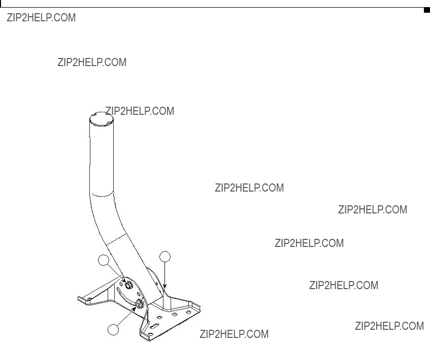
Appendix D Assembling the Rooftop or Wall Mount
Assembling the Mount
Assembling the Mount
Figure
Figure
Appendix D Assembling the Rooftop or Wall Mount
Assembling the Mount
You have completed the assembly of your rooftop or wall mount.
Note You must securely attach the mounting plate to the wall or roof and tighten all nuts (12 to 14
To mount your rooftop or wall mount, please follow the mounting instructions located in the Cisco Aironet 1400 Series Wireless Bridge Mounting Instructions that shipped with your bridge.
Cisco Aironet 1400 Series Wireless Bridge Hardware Installation Guide.

802.11
802.11a
G L O S S A R Y
The IEEE standard that specifies carrier sense media access control and physical layer specifications for 1- and
The IEEE standard that specifies carrier sense media access control and physical layer specifications for wireless LANs operating in the
A
ad hoc network
antenna gain
associated
A wireless network composed of stations without access points.
The gain of an antenna is a measure of the antenna???s ability to direct or focus radio energy over a region of space.
A
B
C
cell
CSMA
The area of radio range or coverage in which the wireless devices can communicate with the base station. The size of the cell depends upon the speed of the transmission, the type of antenna used, and the physical environment, as well as other factors.
Carrier sense multiple access. A wireless LAN media access method specified by the IEEE 802.11 specification.
Cisco Aironet 1400 Series Wireless Bridge Hardware Installation Guide.

Glossary
D
data rates
dBi
dBm
DHCP
dipole
domain name
The range of data transmission rates supported by a device. Data rates are measured in megabits per second (Mbps).
A ratio of decibels to an isotropic antenna that is commonly used to measure antenna gain. The greater the dBi value, the higher the gain, and the more narrow the angle of coverage.
An absolute power level described in decibels referenced to 1 mW. 0 dBm is equivalent to 1 mW.
Dynamic Host Configuration Protocol. A protocol available with many operating systems that automatically issues IP addresses within a specified range to devices on the network. The device retains the assigned address for a specific
A type of
The text name that refers to a grouping of networks or network resources based on
DNS
DSSS
Domain Name System server. A server that translates text names into IP addresses. The server maintains a database of host alphanumeric names and their corresponding IP addresses.
Direct sequence spread spectrum. A type of spread spectrum radio transmission that spreads its signal continuously over a wide frequency band.
E
F
Cisco Aironet 1400 Series Wireless Bridge Hardware Installation Guide.
Glossary
G
I
IEEE
infrastructure
IP address
IP subnet mask
isotropic
Institute of Electrical and Electronic Engineers. A professional society serving electrical engineers through its publications, conferences, and standards development activities. The body responsible for the Ethernet 802.3 and wireless LAN 802.11 specifications.
The wired Ethernet network.
The Internet Protocol (IP) address of a station.
The number used to identify the IP subnetwork, indicating whether the IP address can be recognized on the LAN or if it must be reached through a gateway. This number is expressed in a form similar to an IP address, such as 255.255.255.0.
An antenna that radiates its signal in a spherical pattern.
M
N
O

Glossary
P
R
range
receiver sensitivity
RF
root bridge
A linear measure of the distance that a transmitter can send a signal.
A measurement of the weakest signal a receiver can receive and still correctly translate it into data.
Radio frequency. A generic term for
A wireless transceiver connected to the main Ethernet network that communicates with other wireless transceivers connected to remote Ethernet networks.
S
spread spectrum
SSID
A radio transmission technology that spreads the user information over a much wider bandwidth than otherwise required in order to gain benefits such as improved interference tolerance and unlicensed operation.
Service Set Identifier (also referred to as Radio Network Name). A unique identifier used to identify a radio network and which stations must use to be able to communicate with each other or a bridge. The SSID can be any alphanumeric entry up to 32 characters.
T
transmit power The power level of radio transmission.
U

Glossary
W
Cisco Aironet 1400 Series Wireless Bridge Hardware Installation Guide.
Glossary
Cisco Aironet 1400 Series Wireless Bridge Hardware Installation Guide.

I N D E X
E

Index
inline
input
R
regulatory information
related publications ix reloading bridge image
RF exposure
S
safety warnings, translated
size
SSID, troubleshooting
T
TAC
Telnet
temperature, operating
TFTP server
troubleshooting
U
unpacking
W
warning, defined viii to ix
Cisco Aironet 1400 Series Wireless Bridge Hardware Installation Guide.