Cisco 11000 Series Content Services
Switch Hardware Installation Guide
Software Version 6.10
July 2003
Corporate Headquarters
Cisco Systems, Inc. 170 West Tasman Drive
San Jose, CA 95134-1706
USA http://www.cisco.com Tel: 408 526-4000
800 553-NETS (6387) Fax: 408 526-4100
Text Part Number: 78-15146-02
Customer Order Number: DOC-7815146=
THE SPECIFICATIONS AND INFORMATION REGARDING THE PRODUCTS IN THIS MANUAL ARE SUBJECT TO CHANGE WITHOUT
NOTICE. ALL STATEMENTS, INFORMATION, AND RECOMMENDATIONS IN THIS MANUAL ARE BELIEVED TO BE ACCURATE BUT
ARE PRESENTED WITHOUT WARRANTY OF ANY KIND, EXPRESS OR IMPLIED. USERS MUST TAKE FULL RESPONSIBILITY FOR
THEIR APPLICATION OF ANY PRODUCTS.
THE SOFTWARE LICENSE AND LIMITED WARRANTY FOR THE ACCOMPANYING PRODUCT ARE SET FORTH IN THE INFORMATION
PACKET THAT SHIPPED WITH THE PRODUCT AND ARE INCORPORATED HEREIN BY THIS REFERENCE. IF YOU ARE UNABLE TO
LOCATE THE SOFTWARE LICENSE OR LIMITED WARRANTY, CONTACT YOUR CISCO REPRESENTATIVE FOR A COPY.
The following information is for FCC compliance of Class A devices: This equipment has been tested and found to comply with the limits for a Class A digital device, pursuant to part 15 of the FCC rules. These limits are designed to provide reasonable protection against harmful interference when the equipment is operated in a commercial environment. This equipment generates, uses, and can radiate radio-frequency energy and, if not installed and used in accordance with the instruction manual, may cause harmful interference to radio communications. Operation of this equipment in a residential area is likely to cause harmful interference, in which case users will be required to correct the interference at their own expense.
The following information is for FCC compliance of Class B devices: The equipment described in this manual generates and may radiate radio-frequency energy. If it is not installed in accordance with Cisco???s installation instructions, it may cause interference with radio and television reception. This equipment has been tested and found to comply with the limits for a Class B digital device in accordance with the specifications in part 15 of the FCC rules. These specifications are designed to provide reasonable protection against such interference in a residential installation. However, there is no guarantee that interference will not occur in a particular installation.
Modifying the equipment without Cisco???s written authorization may result in the equipment no longer complying with FCC requirem ents for Class A or Class B digital devices. In that event, your right to use the equipment may be limited by FCC regulations, and you may be required to correct any interference to radio or television communications at your own expense.
You can determine whether your equipment is causing interference by turning it off. If the interference stops, it was probably caused by the Cisco equipment or one of its peripheral devices. If the equipment causes interference to radio or television reception, try to correct the interference by using one or more of the following measures:
???Turn the television or radio antenna until the interference stops.
???Move the equipment to one side or the other of the television or radio.
???Move the equipment farther away from the television or radio.
??? Plug the equipment into an outlet that is on a different circuit from the television or radio. (That is, make certain the equ ipment and the television or radio are on circuits controlled by different circuit breakers or fuses.)
Modifications to this product not authorized by Cisco Systems, Inc. could void the FCC approval and negate your authority to operate the product.
The Cisco implementation of TCP header compression is an adaptation of a program developed by the University of California, Berkeley (UCB) as part of UCB???s public domain version of the UNIX operating system. All rights reserved. Copyright ?? 1981, Regents of the Univers ity of California.
NOTWITHSTANDING ANY OTHER WARRANTY HEREIN, ALL DOCUMENT FILES AND SOFTWARE OF THESE SUPPLIERS ARE
PROVIDED ???AS IS??? WITH ALL FAULTS. CISCO AND THE ABOVE-NAMED SUPPLIERS DISCLAIM ALL WARRANTIES, EXPRESSED
OR IMPLIED, INCLUDING, WITHOUT LIMITATION, THOSE OF MERCHANTABILITY, FITNESS FOR A PARTICULAR PURPOSE AND
NONINFRINGEMENT OR ARISING FROM A COURSE OF DEALING, USAGE, OR TRADE PRACTICE.
IN NO EVENT SHALL CISCO OR ITS SUPPLIERS BE LIABLE FOR ANY INDIRECT, SPECIAL, CONSEQUENTIAL, OR INCIDENTAL
DAMAGES, INCLUDING, WITHOUT LIMITATION, LOST PROFITS OR LOSS OR DAMAGE TO DATA ARISING OUT OF THE USE OR
INABILITY TO USE THIS MANUAL, EVEN IF CISCO OR ITS SUPPLIERS HAVE BEEN ADVISED OF THE POSSIBILITY OF SUCH
DAMAGES.
CCIP, CCSP, the Cisco Arrow logo, the Cisco Powered Network mark, Cisco Unity, Follow Me Browsing, FormShare, and StackWise are trademarks of Cisco Systems, Inc.; Changing the Way We Work, Live, Play, and Learn, and iQuick Study are service marks of Cisco Systems, Inc.; and Aironet, ASIST, BPX, Catalyst, CCDA, CCDP, CCIE, CCNA, CCNP, Cisco, the Cisco Certified Internetwork Expert logo, Cisco IOS, the Cisco IOS logo, Cisco Press, Cisco Systems, Cisco Systems Capital, the Cisco Systems logo, Empowering the Internet Generation, Enterprise/Solver, EtherChannel, EtherSwitch, Fast Step, GigaStack, Internet Quotient, IOS, IP/TV, iQ Expertise, the iQ logo, iQ Net Readiness Scorecard, LightStream, MGX, MICA, the Networkers logo, Networking Academy, Network Registrar, Packet, PIX, Post-Routing, Pre-Routing, RateMUX, Registrar, ScriptShare, SlideCast, SMARTnet, StrataView Plus, Stratm, SwitchProbe, TeleRouter, The Fastest Way to Increase Your Internet Quotient, TransPath, and VCO are registered trademarks of Cisco Systems, Inc. and/or its affiliates in the U.S. and certain other countries.
All other trademarks mentioned in this document or Web site are the property of their respective owners. The use of the word partner does not imply a partnership relationship between Cisco and any other company. (0304R)
Cisco 11000 Series Content Services Switch Hardware Installation Guide
Copyright ?? 2003 Cisco Systems, Inc. All rights reserved.
Contents
Cisco 11000 Series Content Services Switch Hardware Installation Guide
Figures
Cisco 11000 Series Content Services Switch Hardware Installation Guide
Preface
This guide is intended to help you install your Cisco 11000 Series Content Services Switches (CSS), models CSS 11050, CSS 11150, and CSS 11800. It provides you with instructions for installing, cabling, booting, and configuring the CSS. Information in this guide applies to all CSSs except where noted.
This preface describes the following topics:
???Audience
???How to Use This Guide
???Related Documentation
???Symbols and Conventions
???Obtaining Documentation
???Obtaining Technical Assistance
???Obtaining Additional Publications and Information
Cisco 11000 Series Content Services Switch Hardware Installation Guide
Preface
Audience
Audience
Warning Only trained and qualified personnel are allowed to install or replace this equipment.
This guide is intended for the following trained and qualified service personnel who are responsible for installing and operating the CSS:
???System installer
???Hardware technician
???System operator
How to Use This Guide
The following table lists the contents of this guide and describes the contents of each chapter and appendix.
Preface
Related Documentation
Related Documentation
In addition to this document, the CSS documentation set includes the following:
Preface
Related Documentation
Preface
Symbols and Conventions
Symbols and Conventions
This guide uses the following symbols and conventions to emphasize certain information.
Caution A caution means that a specific action you take could cause a loss of data or adversely impact use of the equipment.
Warning A warning describes an action that could cause you physical harm or damage the equipment.
Note A note provides important related information, reminders, and recommendations.
Bold text indicates a command in a paragraph.
Courier text indicates text that appears in a command line, including the CLI prompt.
Courier bold text indicates commands and text you enter in a command line.
Italics text indicates the first occurrence of a new term, book title, emphasized text and variables for which you supply values.
1.A numbered list indicates that the order of the list items is important.
a.An alphabetical list indicates that the order of the secondary list items is important.
Preface
Obtaining Documentation
???A bulleted list indicates that the order of the list topics is unimportant.
???An indented list indicates that the order of the list subtopics is unimportant.
Obtaining Documentation
Cisco provides several ways to obtain documentation, technical assistance, and other technical resources. These sections explain how to obtain technical information from Cisco Systems.
Cisco.com
You can access the most current Cisco documentation on the World Wide Web at this URL:
http://www.cisco.com/univercd/home/home.htm
You can access the Cisco website at this URL:
http://www.cisco.com
International Cisco websites can be accessed from this URL:
http://www.cisco.com/public/countries_languages.shtml
Documentation CD-ROM
Cisco documentation and additional literature are available in a Cisco Documentation CD-ROM package, which may have shipped with your product. The Documentation CD-ROM is updated regularly and may be more current than printed documentation. The CD-ROM package is available as a single unit or through an annual or quarterly subscription.
Registered Cisco.com users can order a single Documentation CD-ROM (product number DOC-CONDOCCD=) through the Cisco Ordering tool:
http://www.cisco.com/en/US/partner/ordering/ordering_place_order_ordering_t ool_launch.html
Cisco 11000 Series Content Services Switch Hardware Installation Guide
Preface
Obtaining Documentation
All users can order monthly or quarterly subscriptions through the online
Subscription Store:
http://www.cisco.com/go/subscription
Ordering Documentation
You can find instructions for ordering documentation at this URL:
http://www.cisco.com/univercd/cc/td/doc/es_inpck/pdi.htm
You can order Cisco documentation in these ways:
???Registered Cisco.com users (Cisco direct customers) can order Cisco product documentation from the Networking Products MarketPlace:
http://www.cisco.com/en/US/partner/ordering/index.shtml
???Nonregistered Cisco.com users can order documentation through a local account representative by calling Cisco Systems Corporate Headquarters (California, U.S.A.) at 408 526-7208 or, elsewhere in North America, by calling 800 553-NETS (6387).
Documentation Feedback
You can submit comments electronically on Cisco.com. On the Cisco
Documentation home page, click Feedback at the top of the page.
You can e-mail your comments to bug-doc@cisco.com.
You can submit comments by using the response card (if present) behind the front cover of your document or by writing to the following address:
Cisco Systems
Attn: Customer Document Ordering
170 West Tasman Drive
San Jose, CA 95134-9883
We appreciate your comments.
Preface
Obtaining Technical Assistance
Obtaining Technical Assistance
Cisco provides Cisco.com, which includes the Cisco Technical Assistance Center (TAC) website, as a starting point for all technical assistance. Customers and partners can obtain online documentation, troubleshooting tips, and sample configurations from the Cisco TAC website. Cisco.com registered users have complete access to the technical support resources on the Cisco TAC website, including TAC tools and utilities.
Cisco.com
Cisco.com offers a suite of interactive, networked services that let you access Cisco information, networking solutions, services, programs, and resources at any time, from anywhere in the world.
Cisco.com provides a broad range of features and services to help you with these tasks:
???Streamline business processes and improve productivity
???Resolve technical issues with online support
???Download and test software packages
???Order Cisco learning materials and merchandise
???Register for online skill assessment, training, and certification programs
To obtain customized information and service, you can self-register on Cisco.com at this URL:
http://tools.cisco.com/RPF/register/register.do
Technical Assistance Center
The Cisco TAC is available to all customers who need technical assistance with a Cisco product, technology, or solution. Two types of support are available: the Cisco TAC website and the Cisco TAC Escalation Center. The type of support that you choose depends on the priority of the problem and the conditions stated in service contracts, when applicable.
Preface
Obtaining Technical Assistance
We categorize Cisco TAC inquiries according to urgency:
???Priority level 4 (P4)???You need information or assistance concerning Cisco product capabilities, product installation, or basic product configuration. There is little or no impact to your business operations.
???Priority level 3 (P3)???Operational performance of the network is impaired, but most business operations remain functional. You and Cisco are willing to commit resources during normal business hours to restore service to satisfactory levels.
???Priority level 2 (P2)???Operation of an existing network is severely degraded, or significant aspects of your business operations are negatively impacted by inadequate performance of Cisco products. You and Cisco will commit full-time resources during normal business hours to resolve the situation.
???Priority level 1 (P1)???An existing network is ???down,??? or there is a critical impact to your business operations. You and Cisco will commit all necessary resources around the clock to resolve the situation.
Cisco TAC Website
The Cisco TAC website provides online documents and tools to help troubleshoot and resolve technical issues with Cisco products and technologies. To access the Cisco TAC website, go to this URL:
http://www.cisco.com/tac
All customers, partners, and resellers who have a valid Cisco service contract have complete access to the technical support resources on the Cisco TAC website. Some services on the Cisco TAC website require a Cisco.com login ID and password. If you have a valid service contract but do not have a login ID or password, go to this URL to register:
http://tools.cisco.com/RPF/register/register.do
If you are a Cisco.com registered user, and you cannot resolve your technical issues by using the Cisco TAC website, you can open a case online at this URL:
http://www.cisco.com/tac/caseopen
If you have Internet access, we recommend that you open P3 and P4 cases online so that you can fully describe the situation and attach any necessary files.
Preface
Obtaining Additional Publications and Information
Cisco TAC Escalation Center
The Cisco TAC Escalation Center addresses priority level 1 or priority level 2 issues. These classifications are assigned when severe network degradation significantly impacts business operations. When you contact the TAC Escalation Center with a P1 or P2 problem, a Cisco TAC engineer automatically opens a case.
To obtain a directory of toll-free Cisco TAC telephone numbers for your country, go to this URL:
http://www.cisco.com/warp/public/687/Directory/DirTAC.shtml
Before calling, please check with your network operations center to determine the Cisco support services to which your company is entitled: for example, SMARTnet, SMARTnet Onsite, or Network Supported Accounts (NSA). When you call the center, please have available your service agreement number and your product serial number.
Obtaining Additional Publications and Information
Information about Cisco products, technologies, and network solutions is available from various online and printed sources.
???The Cisco Product Catalog describes the networking products offered by Cisco Systems, as well as ordering and customer support services. Access the
Cisco Product Catalog at this URL: http://www.cisco.com/en/US/products/products_catalog_links_launch.html
???Cisco Press publishes a wide range of networking publications. Cisco suggests these titles for new and experienced users: Internetworking Terms and Acronyms Dictionary, Internetworking Technology Handbook, Internetworking Troubleshooting Guide, and the Internetworking Design Guide. For current Cisco Press titles and other information, go to Cisco Press online at this URL:
http://www.ciscopress.com
Preface
Obtaining Additional Publications and Information
???Packet magazine is the Cisco quarterly publication that provides the latest networking trends, technology breakthroughs, and Cisco products and solutions to help industry professionals get the most from their networking investment. Included are networking deployment and troubleshooting tips, configuration examples, customer case studies, tutorials and training, certification information, and links to numerous in-depth online resources. You can access Packet magazine at this URL:
http://www.cisco.com/go/packet
???iQ Magazine is the Cisco bimonthly publication that delivers the latest information about Internet business strategies for executives. You can access iQ Magazine at this URL:
http://www.cisco.com/go/iqmagazine
???Internet Protocol Journal is a quarterly journal published by Cisco Systems for engineering professionals involved in designing, developing, and operating public and private internets and intranets. You can access the Internet Protocol Journal at this URL:
http://www.cisco.com/en/US/about/ac123/ac147/about_cisco_the_internet_ protocol_journal.html
???Training???Cisco offers world-class networking training. Current offerings in network training are listed at this URL:
http://www.cisco.com/en/US/learning/le31/learning_recommended_training _list.html
Preface
Obtaining Additional Publications and Information
C H A P T E R 1
Unpacking and Installing the CSS
This chapter describes how to unpack and install the CSS 11050, CSS 11150, and CSS 11800 as free-standing or rack-mount units.
This chapter contains the following major sections:
???Site Requirements
???Shipment Contents
???Unpacking the CSS
???If the Product is Damaged
???Installing the CSS 11050 or CSS 11150
???Installing the CSS 11800
???Installing a CSS 11800 Module
Note For information on installing a replacement or accessory item in the CSS 11800 (such as a redundant AC or DC power supply, or fan unit) consult the reference sheet included with the item.
Chapter 1 Unpacking and Installing the CSS
Site Requirements
Site Requirements
Before you select an installation site for the CSS, read the electrical, environmental, and physical requirements as described in Appendix A, Specifications. If you are installing a DC unit (CSS 11150 or CSS 11800 only), ensure that you read and follow the DC power supply safety warnings in Appendix A, Specifications.
Required Tools and Equipment
To install the CSS hardware, you need the following tools and equipment:
???A Phillips and a flat-head screwdriver
???Anti-static wrist strap (included in the CSS 11800 accessory kit)
???Hand lift (recommended) for lifting the CSS 11800 chassis into the equipment rack
Once you complete the installation, you need a console terminal (or equivalent) that runs at 9600 bps to issue console commands.
Shipment Contents
The CSS 11050, CSS 11150, and CSS 11800 shipment contains the following items except where noted:
???Content Services Switch
???Anti-static wrist strap (CSS 11800 only)
???Four rubber feet (CSS 11050 and CSS 11150)
???Mounting brackets and hardware (CSS 11050 and CSS 11150)
Chapter 1 Unpacking and Installing the CSS
Unpacking the CSS
???Console cable kit:
???RS-232 shielded modem cable
???RJ-45 to female 25-pin sub-d connector
???RJ-45 to female 9-pin sub-d connector
???RJ-45 to RJ-45 Cisco console adapter cable
???Standard software license key. If you ordered the Enhanced feature set, the Secure Management option (which include the Secure Shell Host option and SSL strong encryption for the Device Management software), or the Proximity Database feature, additional Claim Certificates will be included in the Accessory kit.
Note If you cannot locate the Standard software license key or a license key Claim Certificate in the Accessory kit, call the Cisco Technical Assistance Center (TAC) toll free, 24 hours a day, 7 days a week at 1-800-553-2447 or 1-408-526-7209. You can also e-mail TAC at tac@cisco.com.
??? Cisco 11000 Series Content Services Switch Hardware Installation Guide
Unpacking the CSS
The CSS is shipped in a protective shipping carton. The CSS 11050 and
CSS 11150 are shipped as a self-contained chassis; no modules or components can be added or removed. The CSS 11800 is shipped with the power supply, fan unit, SCM, and SFM preinstalled. You must install all separately ordered items (for example, I/O modules or a redundant AC or DC power supply) into the CSS 11800.
This section describes:
???Unpacking the CSS 11050 or CSS 11150
???Unpacking the CSS 11800
Chapter 1 Unpacking and Installing the CSS
Unpacking the CSS
Unpacking the CSS 11050 or CSS 11150
To unpack the CSS 11050 or CSS 11150:
1.Remove the CSS and all accessories from the shipping carton.
2.Check the configuration of the CSS and the accessories against the items listed on the packing slip. Report any discrepancies as described in ???If the Product is Damaged??? in this chapter.
3.To install the CSS 11050 or CSS 11150, go to the ???Installing the CSS 11050 or CSS 11150??? section.
Unpacking the CSS 11800
The CSS 11800 is shipped attached to a wooden pallet with screws and shipping brackets. Due to the large size and weight of a unit, move it to the installation site before unpacking it from the shipping carton.
To unpack the CSS 11800:
1.Remove all enclosed packing materials. Save the packing materials in case you need to repack the CSS later.
2.Remove the accessories from the shipping carton.
3.Check the configuration of the CSS and the accessories against the packing slip. Report any discrepancies as described in the ???If the Product is Damaged??? section later in this chapter.
4.Using a Phillips screwdriver, remove the screws from the shipping brackets on the pallet. Figure 1-1 shows the CSS 11800 attached to the wooden pallet.
5.Carefully remove the CSS from the pallet.
Chapter 1 Unpacking and Installing the CSS
If the Product is Damaged
Figure 1-1 CSS 11800 Shipping Pallet
Shipping
brackets
Shipping
brackets
49566
6. To install the CSS, go to the ???Installing the CSS 11800??? section.
If the Product is Damaged
If any portion of the unit or component is damaged in transit, forward an immediate request to the delivering carrier to perform an inspection of the product and to prepare a damage report. Save the container and all packing materials until the contents are verified.
Chapter 1 Unpacking and Installing the CSS
Installing the CSS 11050 or CSS 11150
Concurrently, report the nature and extent of the damage to Customer Service. Report the problem or deficiency to Customer Service along with the model number and serial number. Upon receipt of this information, you will be provided with service instructions, or a Return Material Authorization (RMA) Number and shipping information.
Installing the CSS 11050 or CSS 11150
The CSS 11050 or CSS 11150 can be placed on a flat surface as a free-standing unit or rack-mounted in an equipment cabinet. The following sections describe the steps to install the CSS as a:
???Free-standing unit
???Rack-mounted unit
Prior to installing the CSS, observe the following installation requirements:
???The ambient operating temperature is 32?? to 104?? F (0 to 40?? C).
If you install the CSS in a closed or multi-unit rack, the operating ambient temperature of the rack environment may be greater than the room ambient temperature. Ensure that the temperature does not exceed the CSS maximum ambient operating temperature.
???The minimum clearance requirement is 2 inches (10 cm) of air flow space on both sides of the chassis.
???Ensure that the CSS is reliably grounded to earth. We recommend that you do not use power strips or extension cords to connect the CSS to the power source.
Caution Do not remove the CSS 11050 or CSS 11150 cover. There are electrical shock hazards present in the unit if the cover is removed. There are no serviceable or installable components available with the CSS 11050 and CSS 11150.
Do not use a 3-prong to 2-prong electrical adapter. This will compromise the grounding.
Note Removing the CSS 11050 or CSS 11150 cover voids its warranty.
Chapter 1 Unpacking and Installing the CSS
Installing the CSS 11050 or CSS 11150
Installing the CSS 11050 or CSS 11150 as a Free-Standing Unit
Position the CSS 11050 or CSS 11150 on the selected flat surface. When installing the CSS, note that all cables connect to the front of the unit with the exception of the cable that connects to the Ethernet management port on the rear panel and the power cord.
Rack-Mounting the CSS 11050 or CSS 11150
Before you rack-mount the CSS 11050 or CSS 11150:
???Determine if you want to front-mount or mid-mount the CSS chassis into the cabinet. The difference between front-mount or mid-mount is:
???Front-mount sets the front edge of the unit even with the front edge of the rack
???Mid-mounting the CSS sets the front edge of the unit past the front edge of the rack
???Install the mounting brackets on the CSS. The rack position of the CSS determines where you will install the mounting brackets on the CSS chassis. See the following section to install the mounting brackets.
Installing the Mounting Brackets
Before you begin, you will need the mounting brackets and eight screws shipped in the accessory kit accompanying the CSS 11050 and CSS 11150, and a #2 Phillips screwdriver.
To install the mounting brackets on the CSS chassis:
1.Position the CSS with its front panel facing you. On the left and right side of its chassis, note the screw holes for installing the mounting brackets.
2.Position a bracket on one side of the chassis. Align the bracket with the appropriate screw holes for front- or mid-mounting.
Figure 1-2 illustrates front-mounting the brackets. Figure 1-3 illustrates mid-mounting the brackets.
Chapter 1 Unpacking and Installing the CSS
Installing the CSS 11050 or CSS 11150
Figure 1-2 Front-Mounting the Brackets on the CSS 11050 or CSS 11150
49567
Figure 1-3 Mid-Mounting the Brackets on the CSS 11050 and CSS 11150
49568
3.Secure the bracket to the CSS with four screws.
4.Repeat steps 2 and 3 to install a mounting bracket on the other side of the CSS.
You are ready to install the CSS in the cabinet.
Installing the CSS into the Rack
Before you begin, you will need a #2 Phillips screwdriver and four pan-head screws. To install the CSS 11050 or CSS 11150 into an equipment rack:
1.Raise the CSS to the installation height. Align the screw holes on the mounting bracket with the holes on the equipment rack.
Chapter 1 Unpacking and Installing the CSS
Installing the CSS 11800
2.Use a #2 Phillips screwdriver and two pan-head screws to secure each mounting bracket to each side of the rack.
Installing the CSS 11800
The CSS 11800 is a rack-mount unit. When positioning the CSS 11800 for installation, keep in mind that all cables connect to the front of the unit.
Prior to rack-mounting the CSS, observe the following installation requirements:
???The maximum ambient operating temperature for the CSS 11800 is 32?? to 104?? F (0 to 40?? C). When you install the CSS 11800 in a closed or multi-unit rack, the operating ambient temperature of the rack environment may be greater than the room ambient temperature. Ensure that the temperature does not exceed the CSS maximum ambient operating temperature.
???Ensure that the CSS 11800 is reliably grounded to earth. Do not use power strips or extension cords to connect the CSS to the power source.
Before you rack-mount the CSS 11800 chassis, determine if you want to front-mount, mid-mount, or extend-mount the chassis in the cabinet:
???Front-mount the chassis to set the front edge of the unit even with the front edge of the rack. The brackets are preinstalled in this position on the chassis and are ready for mounting in a rack, as described in the ???Rack-Mounting the CSS 11800 Chassis??? section.
???Mid-mount the chassis to set the front edge of the unit in front of the front edge of the rack. To mid-mount the brackets on the chassis, follow the steps in ???Mid-Mounting the CSS 11800 Brackets??? .
???Extend-mount the chassis to set the front edge of the unit behind the front edge of the rack; allowing the chassis to be installed in an enclosed rack. To extend-mount the brackets on the chassis, follow the steps in ???Extend-Mounting the CSS 11800 Brackets??? .
Mid-Mounting the CSS 11800 Brackets
To change the location of the mounting brackets on the CSS 11800 chassis from
afront-mount position to a mid-mount position (see Figure 1-4):
1.Remove the seven front mounting bracket screws from one side of the chassis.
Chapter 1 Unpacking and Installing the CSS
Installing the CSS 11800
2.Position the mounting bracket onto the middle of one side of the CSS, lining up the front screw holes on the bracket with the holes on the side of the chassis.
Figure 1-4 Aligning Brackets on the CSS 11800 for Mid-Mounting
 Mounting
bracket
Mounting 
bracket

 Mounting
key
Mounting
key
49569
3.Using a Phillips screwdriver, install only five of the seven #10-32 pan-head screws through the mid-mount bracket holes into the CSS. Do not install the screws in the top of the bracket or second from the bottom of the bracket.
4.Repeat steps 1 through 3 to install the second bracket onto the other side of the chassis.
When the brackets are in position for mounting the chassis in a rack, proceed to the ???Rack-Mounting the CSS 11800 Chassis??? section.
Chapter 1 Unpacking and Installing the CSS
Installing the CSS 11800
Extend-Mounting the CSS 11800 Brackets
You can extend-mount a CSS 11800 chassis to set the front edge of the unit behind the front edge of the rack to allow the chassis to be installed in an enclosed rack. Before you can extend-mount a chassis, you need to reposition its mounting brackets. Each bracket has two sets of screw holes. The set of holes you use to install the brackets to the chassis determines how the chassis is mounted in a rack:
???The screw holes toward the front of the bracket position each bracket on the CSS 11800 chassis for front mounting in a cabinet; this is the preinstalled position.
???The screw holes behind the first set of holes position each bracket on the CSS 11800 chassis for extended mounting in a cabinet.
Figure 1-5 illustrates extend-mounting the brackets.
Figure 1-5 Screw Holes on the CSS 11800 Bracket for Front and Extended
Mounting
Chapter 1 Unpacking and Installing the CSS
Installing the CSS 11800
To change the location of the mounting brackets on the CSS 11800 chassis from
afront-mount position to an extended-mount position:
1.Remove the seven front mounting bracket screws from one side of the chassis.
2.Align the rear screw holes on the bracket with the screw holes on the front side of the chassis. Note the bracket???s proper orientation as shown in Figure 1-6.
Figure 1-6 Aligning Brackets on the CSS 11800 Chassis for Extended Mounting
Mounting bracket
Mounting
bracket
Mounting key
Mounting
key
49571
3.Using a Phillips screwdriver, install the seven #10-32 pan-head screws through the extended-mount bracket holes into the CSS.
4.Repeat steps 1 through 3 to install the second bracket onto the other side of the chassis.
Chapter 1 Unpacking and Installing the CSS
Installing the CSS 11800
When the brackets are in position for mounting the chassis in a rack, proceed to the ???Rack-Mounting the CSS 11800 Chassis??? section.
Rack-Mounting the CSS 11800 Chassis
Once the mounting brackets are installed, you are ready to install the CSS 11800 chassis.
Warning The weight and position of the CSS 11800 chassis within the cabinet may make the cabinet top-heavy or unstable. Take all necessary precautions to anchor the cabinet securely before installing the chassis.
To install the CSS 11800 chassis into a cabinet:
1.Locate the mounting keys on the left and right mounting brackets (see Figure 1-4). Mounting keys are designed to fit over pan-head screws installed in the mounting rack to hold the chassis in place while you secure the chassis into the rack.
2.Install a pan-head screw into the left and right sides of the mounting rack. These screws fit into the mounting keys and hold the chassis.
3.Raise the CSS to the appropriate installation height and place the mounting keys over the installed pan-head screws. The CSS is now held in place by the mounting keys so you can install the remaining screws.
4.Align the screw holes on the mounting bracket with the screw holes on the equipment cabinet and install the pan-head screws through the CSS and cabinet brackets. The CSS 11800 requires five pan-head screws for each side of the chassis.
Chapter 1 Unpacking and Installing the CSS
Installing a CSS 11800 Module
Installing a CSS 11800 Module
This section applies to the CSS 11800 modules only and contains the following sections:
???Installation Precautions and Restrictions
???Unpacking a CSS 11800 Module
???Installing a Module
???Installing a Passive SCM or SFM
Installation Precautions and Restrictions
This section includes background material related to installing a module into the CSS 11800 chassis. It is recommended that you read the topics in this section before installing a module.
Installation Precautions
Read and observe the following precautionary information prior to servicing the CSS 11800.
Warning Do not remove or install modules without using appropriate anti-static guard measures. The CSS includes an anti-static wrist strap in the accessory kit. Attach the copper tape end of the strap to an unpainted metal surface on the chassis. You can leave the strap connected to the chassis when you are done.
Warning If you do not power down the CSS 11800, an electrical energy hazard is present within the chassis. Prior to installing or removing components, remove all metallic objects from hands and wrists to prevent bridging of live contact points.
Chapter 1 Unpacking and Installing the CSS
Installing a CSS 11800 Module
Module Slot Restrictions
Modules are restricted to specific slots due to bandwidth capabilities. The CSS 11800 chassis backplane is designed for specific modules to reside in their respective slots. For example, you cannot install a SCM in slot 2 because the backplane connector for slot 2 does not accommodate a SCM connector. Prior to installing a module, see Table 1-1 for information on chassis slot usage.
Table 1-1 Chassis Slot Usage
Chapter 1 Unpacking and Installing the CSS
Installing a CSS 11800 Module
Figure 1-7 illustrates a fully configured CSS 11800.
Figure 1-7 Fully Configured CSS 11800
49572
Chapter 1 Unpacking and Installing the CSS
Installing a CSS 11800 Module
Removing or Installing a Module
You must power down the CSS 11800 chassis to remove or install a module. If you install a new module while the CSS is operational, the SCM will not recognize the module until the next reboot.
Warning If you replace an active SCM with a new SCM, the boot configuration reverts back to its default settings. You must reconfigure these parameters through the Offline Diagnostic Monitor menu. For more information on accessing and using this menu, refer to the Content Services Switch Administration Guide.
When you remove a module and replace it with a module of the same type, the SCM automatically downloads the boot image and configuration files for the module. (For information on image and configuration files, refer to the Content Services Switch Administration Guide.) The newly installed module boots up with:
???The appropriate module image
???The same configuration as the former module
When you remove a module and replace it with a module of a different type, the SCM downloads the module boot image automatically. The newly installed module boots up with the appropriate module image.
Unpacking a CSS 11800 Module
To unpack a CSS 11800 module:
1.Verify that the module is the model you ordered by checking the model number listed on the side of the shipping carton
2.Remove the module, in its anti-static bag, from the shipping carton.
3.Put on the anti-static strap provided with your CSS.
4.Remove the module from the anti-static shielding bag and inspect it for damage.
Always hold the module by the faceplate, being careful not to touch the components. If the module appears to be damaged, return it to the anti-static bag, repack it in the shipping carton, and contact your local supplier.
Chapter 1 Unpacking and Installing the CSS
Installing a CSS 11800 Module
5.For the procedure on installing a module into the CSS 11800 chassis, see the ???Installing a Module??? section.
Installing a Module
You must power down the CSS 11800 chassis to install a module.
Note For the procedure on installing a passive SCM or SFM, see the ???Installing a Passive SCM or SFM??? section. For information on removing and replacing a module, see the ???Removing or Installing a Module??? section.
To install a module:
1.Properly ground yourself prior to handling the module. For example, wear the anti-static wrist strap (included in the accessory kit) and stick the copper-tape end of the strap to an unpainted metal surface on the chassis. Make sure that the wrist strap makes good contact with your skin.
2.Locate an open slot in the chassis for the module. See Table 1-1 to identify possible slots for the module. If necessary, remove a blank panel from the chassis to expose a slot for the module.
Chapter 1 Unpacking and Installing the CSS
Installing a CSS 11800 Module
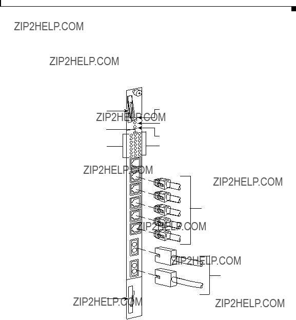
3.Insert the module into the board guides at the top and bottom of the slot and slide it into the chassis by pressing firmly at the top and bottom of the faceplate as shown in Figure 1-8.
Figure 1-8 Installing a Module into a CSS 11800 Chassis
49573
4.Close both ejectors simultaneously to seat the module connector into the backplane.
5.Using a Phillips screwdriver, tighten the spring-loaded screws on the front of the module faceplate. Once you install the module, it begins diagnostics and initializes automatically.
If you installed a SFM or SFM2, you must reboot the chassis to activate it.
6.If you are installing additional GBICs in a Gigabit Ethernet module, position the GBIC with its receive connector above its transmit connector.
Chapter 1 Unpacking and Installing the CSS
Installing a CSS 11800 Module
Installing a Passive SCM or SFM
You can install a passive SCM or SFMs (which includes SFM2s) in a CSS 11800 chassis. Passive modules are stand-by modules in case of an active module failure. When an active module fails, the passive module becomes active. Passive modules do not load share processing functions with the active module.
Note The SCM contains a small lithium battery. Some jurisdictions restrict the ways in which items containing lithium batteries may be disposed. In particular, lithium batteries or products containing lithium batteries may never be disposed of in an unregulated fire. Other restrictions might apply. See Appendix A, Specifications for lithium battery disposal warnings.
Warning Ultimate disposal of a lithium battery should be handled according to all national laws and regulations.
The CSS 11800 enables you to install a passive:
???SCM for the active SCM
???SFM for each of the two active SFMs (total of four SFMs)
Note You can mix SFMs with SFM2s in the same CSS 11800 chassis. However, you must use the same type module as the active SFM and as the passive SFM.
To install a passive SCM or SFM:
1.Properly ground yourself prior to handling the module.
2.If the CSS is powered up, power it down.
3.As defined in Table 1-1:
???SCMs are restricted to slots 7 or 8
???Passive SFMs are restricted to slots 5 and 10 (by default, active SFMs are in slots 6 and 9, respectively)
4.If necessary, remove a blank panel from the chassis to expose a slot.
Chapter 1 Unpacking and Installing the CSS
Installing a CSS 11800 Module
5.Insert the module into the board guides at the top and bottom of the slot and slide it into the chassis by pressing firmly at the top and bottom of the faceplate.
6.Close both ejectors simultaneously to seat the module connector into the backplane.
7.Using a Phillips screwdriver, tighten the spring-loaded screws on the front of the module faceplate.
???A SCM module begins diagnostics and initializes automatically.
???To power on the SFM or SFM2, reboot the CSS.
8.Power up the CSS.
9.To copy the boot configuration from the active SCM to the passive SCM, use the passive sync command in boot configuration mode.
Passive Module Switchover
If the active SCM fails:
1.The CSS reboots and connections are terminated.
2.The CSS restores all configurations using the startup-config file.
3.The passive SCM becomes active automatically.
If an active SFM or SFM2 fails:
1.The CSS performs a cold boot and connections are terminated.
2.The CSS restores all configurations using the startup-config file.
3.A passive SFM becomes active automatically.
Note When the CSS 11800 chassis contains two passive SFMs or SFM2s and an active switchover occurs, both passive SFMs or SFM2s switchover to become active SFMs.
Chapter 1 Unpacking and Installing the CSS
Installing a CSS 11800 Module
C H A P T E R 2
Cabling the CSS
This chapter describes the individual CSS interfaces, how to cable the CSS and its interfaces, how to attach a console for console management, and how to connect the AC or DC power cord. This chapter also describes the CSS LEDs and connectors. The information in this chapter applies to the CSS 11050, CSS 11150, and CSS 11800 except where noted.
This chapter contains the following major sections:
???Cabling the CSS 11050 and CSS 11150
???Cabling the CSS 11800 Modules
???Connecting Power Cords
???Connecting the Console to the CSS
???Powering Up the CSS
???Powering Down the CSS
???Troubleshooting CSS Hardware Components
Cabling the CSS 11050 and CSS 11150
The CSS 11050 and CSS 11150 are fixed configuration devices designed for small Web sites or remote satellite Web sites. Each of these devices provide 5 Gbps of switch bandwidth and integrated LAN ports. They feature all of the networking software capabilities necessary for connecting remote Web sites to the Internet or the home Web site.
Chapter 2 Cabling the CSS
Cabling the CSS 11050 and CSS 11150
Figure 2-1 illustrates a CSS 11151 with 12 auto-sensing 10/100-Mbps Ethernet (10BASE-T/100BASE-TX) interfaces.
Figure 2-1 CSS 11151 Content Services Switch
49574
The CSS 11050 configuration supports:
???Eight auto-sensing 10/100-Mbps Ethernet (10BASE-T/100BASE-TX) interfaces
???Optional integrated Gigabit Ethernet Network Interface Card (GENIC) with one uplink port
The CSS 11150 configuration supports:
???12 auto-sensing 10/100-Mbps Ethernet (10BASE-T/100BASE-TX) interfaces
???Optional integrated Gigabit Ethernet Network Interface Card (GENIC) with two GBIC ports, in either 4 MB or 8 MB per port versions
???Optional integrated Fast Ethernet Network Interface Card (FENIC) with four SC connectors for uplinks
???Optional integrated Fast Ethernet Network Interface Card (FENIC) with four additional auto-sensing 10/100-Mbps Ethernet (10BASE-T/100BASE-TX) interfaces for a total of 16 interfaces
Chapter 2 Cabling the CSS
Cabling the CSS 11050 and CSS 11150
CSS 11050 and CSS 11150 Rear Panel Connectors and LEDs
The CSS 11050 and CSS 11150 have connectors and LEDs on their front and rear panels. The rear panel has an AC connector (or DC connector on a CSS 11150), an Ethernet management RJ-45 connector, and the associated Ethernet Link/Activity, 10/100 (Mbps), and Duplex (Half or Full) LEDs, as shown in Figure 2-2.
Figure 2-2 CSS 11050 and CSS 11150 Rear Panel Connectors and LEDs
Management
 Link/Act
 Duplex
 10/100
10/100 Ethernet
Table 2-1 describes the LEDs on the rear panel.
Table 2-1 CSS 11050 and CSS 11150 Ethernet Management Port LED
Descriptions
Chapter 2 Cabling the CSS
Cabling the CSS 11050 and CSS 11150
CSS 11050 Front Panel Connectors and LEDs
All front panels of the CSS 11050 models contain connectors and LEDs that vary according to their model number. For example, the CSS 11051 in Figure 2-3 has:
???One RS-232 Console connector (9600 baud)
???One RS-232 Diag connector, reserved for field service use only (115,200 baud)
???Eight auto-sensing 10/100-Mbps Fast Ethernet connectors and associated Link/Activity status, 10/100 (Mbps), and Duplex (Half or Full) LEDs
???Power, Status, and Ready LEDs
Figure 2-3 CSS 11051 Front Panel Connectors and LEDs
2X 4X 6X 8X
Console Diag
RS-232 1X 3X 5X 7X
 Power
Power
Status
 Ready
Ready
The CSS 11052 (shown in Figure 2-4) also has one Gigabit Ethernet connection using a Gigabit Interface Converter (GBIC), and associated Transmit, Receive, and Link LEDs. The GBIC complies with Revision 5.1 of the GBIC specification for Class 4 GBICs. The GBIC network interface complies with the IEEE 1000BASE-SX specification for short laser wavelength of 850 nm and use SC-type fiber connectors.
Figure 2-4 CSS 11052 Front Panel Connectors and LEDs
Gigabit Ethernet port (left - receive, right - transmit) and LEDs
Chapter 2 Cabling the CSS
Cabling the CSS 11050 and CSS 11150
Table 2-2 CSS 11050 Front Panel LED Descriptions
Chapter 2 Cabling the CSS
Cabling the CSS 11050 and CSS 11150
CSS 11150 Front Panel Connectors and LEDs
All front panels of the CSS 11150 models front panels contain connectors and LEDs that vary according to their model number. For example, the CSS 11151 front panel in Figure 2-5 has:
???One RS-232 Console connector (9600 baud)
???One RS-232 Diag connector, reserved for field service use only (115,200 baud)
???12 auto-sensing 10/100-Mbps Fast Ethernet connectors and associated Link/Activity status, 10/100 (Mbps), and Duplex (Half or Full) LEDs
???Power, Status, and Ready LEDs
Figure 2-5 CSS 11151 Front Panel Connectors and LEDs
 Power
Power
Status
 Ready
Ready
The CSS 11152 (shown in Figure 2-6) has four additional Fast Ethernet TX connectors and their associated Link/Activity status, 10/100 (Mbps), and Duplex (Half or Full) LEDs.
Figure 2-6
Console Diag
RS-232
CSS 11152 Front Panel Connectors and LEDs
Additional Fast Ethernet TX connectors and LEDs
Chapter 2 Cabling the CSS
Cabling the CSS 11050 and CSS 11150
The CSS 11153 (shown in Figure 2-7) has four additional Fast Ethernet 100BASE-FX SC fiber connectors and their associated Link and Activity LEDs.
Figure 2-7 CSS 11153 Front Panel Connectors and LEDs
Additional Fast Ethernet FX connectors and LEDs
The CSS 11154 (shown in Figure 2-8) has two 1000-Mbps Gigabit Ethernet connections using Gigabit Interface Converters (GBICs) and their associated Transmit, Receive, and Link LEDs. The GBICs comply with Revision 5.1 of the GBIC specification for Class 4 GBICs. The GBIC network interfaces comply with the IEEE 1000BASE-SX specification for short laser wavelength of 850 nm and use SC-type fiber connectors.
Figure 2-8 CSS 11154 Front Panel Connectors and LEDs
Additional Gigabit Ethernet connectors and LEDs
Note The CSS 11155 has a similar appearance to the CSS 11154, but its memory size per port is 8 MB instead of 4 MB.
Cisco 11000 Series Content Services Switch Hardware Installation Guide
Chapter 2 Cabling the CSS
Cabling the CSS 11050 and CSS 11150
Table 2-3 describes the LEDs on the CSS 11150.
Table 2-3 CSS 11150 Front Panel LED Descriptions
Chapter 2 Cabling the CSS
Cabling the CSS 11800 Modules
CSS 11800 Product Description
The CSS 11800 is a 15-slot modular switching chassis with a high speed switching fabric. The CSS 11800 offers LAN connectivity and scalable switch capacity. Designed for larger, mission-critical Web sites, the CSS 11800 provides 20 Gbps of switching bandwidth and high port density LAN ports interfaces. The CSS 11800 CSS is a Carrier Class platform with high performance and scalability and no single point of failure. In case of a disk failure, traffic is still passed in and out of the CSS.
The CSS 11800 configuration provides:
???20 Gbps of switching bandwidth (with support for an optional redundant 20-Gbps switch fabric)
???128 MB Switch Control Module (SCM), model CSS8-SCM (with support for an optional passive SCM)
???10-Gbps Switch Fabric Module 2 (SFM2), model CSS8-SFM2 (with support for an optional passive SCM2)
???Hard drive-based Internal Disk Module (IDM), model CSS8-IDM-MEM-HD, for logging and off-line system files
???Eight slots configurable with either:
???Fast Ethernet modules providing eight auto-sensing 10/100-Mbps Ethernet (10BASE-T/100BASE-TX) RJ-45 ports or six 10BASE-T/100BASE-TX ports and two 100BASE-FX ports
???Gigabit Ethernet modules providing up to four 1000-Mbps Ethernet (1000BASE-SX) Gigabit Interface Converter (GBIC) interfaces with either 8 megabytes of flow connection memory supporting up to 64,000 simultaneous flows or 16 megabytes of flow connection memory supporting up to 128,000 simultaneous flows
???Optional flash-based Internal Disk Module (IDM), model CSS8-IDM-MEM-HD, in place of the hard drive-based IDM
Chapter 2 Cabling the CSS
Cabling the CSS 11800 Modules
Figure 2-9 illustrates a CSS 11800.
Figure 2-9 CSS 11800 Content Services Switch
49582
Chapter 2 Cabling the CSS
Cabling the CSS 11800 Modules
Switch Control Module Connectors and LEDs
The Switch Control Module (SCM) provides master control and packet memory storage and is responsible for the following functions:
???System powerup and boot control
???Centralized routing table management
???System-wide connection management
???Interface to external Network Management Station
???Disk management (internal disk module)
???Provides two external RS-232 interfaces
???Building Integrated Timing Service support
While only one SCM is required in a configuration, you can install and configure a passive SCM for redundancy. A maximum of two SCMs are allowed in a chassis.
Note The SCM contains a small lithium battery. Some jurisdictions restrict the ways in which items containing lithium batteries may be disposed. In particular, lithium batteries or products containing lithium batteries may never be disposed of in an unregulated fire. Other restrictions might apply. See Appendix A, Specifications for lithium battery disposal warnings.
Warning Ultimate disposal of the lithium battery should be handled according to all national laws and regulations.
Switch Control Module Connectors
The Switch Control Module (model CSS8-SCM) contains the following connectors and LEDs:
???One RJ-45 10/100-Mbps Fast Ethernet management connector
???One RJ-45 RS-232 Console connector
???One RJ-45 RS-232 Diag connector (reserved for field service diagnostic use only)
Chapter 2 Cabling the CSS
Cabling the CSS 11800 Modules
???One RJ-45 Building Integrated Timing Supply (BITS) Clock RS-422 connector
???Power, Status, and Active module LEDs
???Duplex, 10/100, and Active LEDs for the Fast Ethernet port
???Power Supply 1 and 2 LEDs
Figure 2-10 illustrates the SCM front panel connectors and LEDs.
Figure 2-10 Switch Control Module Connectors and LEDs

 10/100 Ethernet connector

 Console connector

 Diag connector
Power supply 1 LED


 Timing BITS connector
Power supply 2 LED

 49583
49583
Chapter 2 Cabling the CSS
Cabling the CSS 11800 Modules
Switch Control Module LEDs
The SCM front panel LEDs indicate module and configuration status. Table 2-4 describes the SCM LEDs and their indications.
Table 2-4 Switch Control Module LED Descriptions
Chapter 2 Cabling the CSS
Cabling the CSS 11800 Modules
Configuring a Terminal to the SCM Console Port
This section describes how to configure a terminal connected to the SCM console port. Initially, the terminal settings must match the CSS default settings as specified in Table 2-5.
Table 2-5 CSS Console Port Default Settings
Fast Ethernet Module Connectors and LEDs
The FEM is available in two models:
???Model CSS8-IOM-8FE contains eight auto-sensing RJ-45 Fast Ethernet 10/100-Mbps 10BASE-T/100BASE-TX connectors
???Model CSS8-IOM-6/2FE contains six auto-sensing RJ-45 Fast Ethernet 10/100-Mbps 10BASE-T/100BASE-TX connectors and two 100BASE-FX SC fiber connectors
Chapter 2 Cabling the CSS
Cabling the CSS 11800 Modules
Each model contains Power, Status, and Ready LEDs for module status and Duplex, Speed, and Link LEDs for each of the eight connectors. Figure 2-11 illustrates the LEDs and connectors on the 8-port FEM.
Figure 2-11 8-Port Fast Ethernet Module Connectors and LEDs
RJ-45 10BASE-T/100BASE-TX connectors

 49584
49584
Chapter 2 Cabling the CSS
Cabling the CSS 11800 Modules
Figure 2-12 illustrates the LEDs and connectors on the FEM model
CSS8-IOM-6/2/FE.
Figure 2-12 Fast Ethernet Module with 6 10BASE-T/100BASE-TX Connectors, Two 100BASE-FX SC Fiber Connectors, and LEDs
RJ-45 10BASE-T/100BASE-TX connectors
Fiber SC connectors

 49585
49585
Chapter 2 Cabling the CSS
Cabling the CSS 11800 Modules
Fast Ethernet Module LEDs
The FEM front panel LEDs indicate module and network status. Table 2-6 describes the FEM LEDs.
Table 2-6 Fast Ethernet Module LED Descriptions
Gigabit Ethernet Module Connectors and LEDs
The GEM is available in two models:
???Model CSS8-IOM-4GE/8 contains four Gigabit Interface Converter (GBIC) slots and 8 MB Flow Cache SRAM memory supporting up to 64,000 simultaneous flows. CSS8-GBIC-SX is sold separately.
???Model CSS8-IOM-4GE/16 contains four GBIC slots and 16 MB Flow Cache SRAM memory supporting up to 128,000 simultaneous flows. CSS8-GBIC-SX is sold separately.
Chapter 2 Cabling the CSS
Cabling the CSS 11800 Modules
Figure 2-13 illustrates the LEDs and connectors on a GEM.
Figure 2-13 Gigabit Ethernet Module Connectors and LEDs
Gigabit interface converter (GBIC) SC fiber connectors (top - receive, bottom - transmit)
Ports 2 through 4 for additional GBIC connectors

 49586
49586
Chapter 2 Cabling the CSS
Cabling the CSS 11800 Modules
Gigabit Ethernet Module LEDs
The GEM front panel LEDs indicate module status (Power, Status, and Ready LEDs) and network status for each of the connectors (Transmit, Receive, and Link LEDs). Table 2-7 describes the GEM LEDs.
Table 2-7 Gigabit Ethernet Module LED Descriptions
Chapter 2 Cabling the CSS
Cabling the CSS 11800 Modules
Switch Fabric Module (SFM and SFM2) Connectors and LEDs
The Switch Fabric Module (SFM or SFM2) sets up and tears down flow connections, monitors switch operation, and performs switch functions. The I/O modules use the SFM processors to perform routing functions, including resolution of unknown addresses, route determinations, protocol processing, and other exception events.
Each module provides 10-Gbps switch control element for switching functionality and flow processing for four I/O modules. You can install a second active module to service four additional I/O modules. Both active modules are on simultaneously in the CSS 11800. The chassis enables you to configure two additional passive modules for redundancy. Therefore, you can configure a total of four SFMs or SFM2s in a chassis, of which only two would be active at any time.
Note When the CSS 11800 contains two passive SFMs and an active SFM switchover occurs, both passive SFMs switchover to become active SFMs.
You can mix SFMs with SFM2s in the same CSS 11800 chassis. However, you must use the same type module as the active SFM and as the passive SFM.
The Switch Fabric Module (SFM and SFM2) contains Power, Status, and Active LEDs. The SFM has four RJ-45 RS-232 Console and Diag connectors (all of these connectors are reserved for field service diagnostic use only).
Chapter 2 Cabling the CSS
Cabling the CSS 11800 Modules
Figure 2-14 illustrates the SFM front panel LEDs and connectors.
Figure 2-14 Switch Fabric Module Connectors and LEDs
 Status LED
 Active LED
Debug console and diag console

 49587
49587
The SFM2 contains two RJ-45 RS-232 Diag1 and Diag 2 connectors, combining both Console and Diag functions on each connector (all of these connectors are reserved for field service diagnostic use only).
Chapter 2 Cabling the CSS
Cabling the CSS 11800 Modules
Note These connectors are for serial data only and are not compatible with Ethernet RJ-45 cable connectors.
Figure 2-15 illustrates the SFM2 (model CSS8-SFM2) front panel LEDs and connectors.
Figure 2-15 Switch Fabric Module 2 Connectors and LEDs
 Status LED
 Active LED
Console/diag connectors (Diag 1 and Diag 2)
 49588
49588
Chapter 2 Cabling the CSS
Cabling the CSS 11800 Modules
SFM and SFM2 LEDs
The SFM and SFM2 front panel LEDs indicate operating and configuration status. Table 2-8 describes the SFM LEDs.
Table 2-8 Switch Fabric Module LED Descriptions
Internal Disk Module LEDs
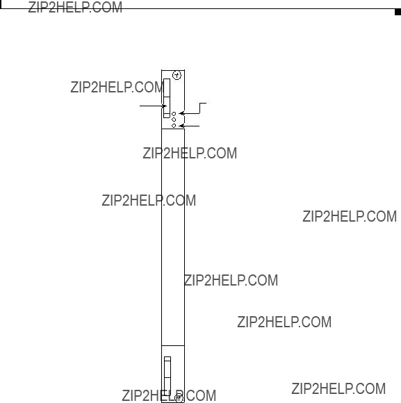
The Internal Disk Module (IDM) in slot 15 contains Power, Status, and Active LEDs. Figure 2-16 illustrates the IDM front panel LEDs. The LEDs apply to both the flash-based (model CSS8-IDM-MEM-FD) or hard drive-based (model CSS8-IDM-MEM-HD) IDM.
Chapter 2 Cabling the CSS
Cabling the CSS 11800 Modules
Figure 2-16 Internal Disk Module LEDs
 Status LED
 Active LED
Module ejector 
49589
Chapter 2 Cabling the CSS
Connecting Power Cords
Internal Disk Module LEDs
The CSS 11800 IDM front panel LEDs indicate operating and activity status.
Table 2-9 describes the IDM LEDs.
Table 2-9 CSS 11800 Internal Disk Module LED Descriptions
Connecting Power Cords
The CSS 11050 models are powered by an AC power supply. The CSS 11150 and CSS 11800 are powered by either an AC or DC power supply. Before you install the AC or DC power cord, ensure that you have read Appendix A, Specifications for electrical specifications. The following sections describe:
???Connecting a CSS 11050 or CSS 11150 Power Cord
???Connecting a CSS 11800 Power Cord
Connecting a CSS 11050 or CSS 11150 Power Cord
The following sections provide information on:
???Connecting a CSS 11050 or CSS 11150 AC Power Cord
???Connecting a CSS 11150 DC Power Cord
Note The CSS 11050 is only available in an AC version.
Chapter 2 Cabling the CSS
Connecting Power Cords
Connecting a CSS 11050 or CSS 11150 AC Power Cord
To connect an AC power cord to a CSS 11050 or CSS 11150:
1.Ensure that the CSS power switch is in the 0 (off) position.
2.Attach the power cord to the CSS by plugging the AC power cord connector into the power receptacle at the rear panel, as shown in Figure 2-17.
Figure 2-17 Connecting a CSS 11050 or CSS 11150 AC Power Cord
AC -100 -240 VAC 50 - 60HZ 3.1AMax.
49590
3.Plug the power cord into a dedicated 3-wire grounding receptacle.
4.Switch on the power on the CSS.
Connecting a CSS 11150 DC Power Cord
Before you install a DC power cord, see Appendix A, Specifications for DC power supply safety warnings.
Warning The DC power supply cord requires 18 AWG wire. The CSS 11150 draws a maximum of 25 amps.
Warning DC systems do not have a power switch. A chassis configured for DC power requires an external power disconnect device (such as an external circuit breaker).
Chapter 2 Cabling the CSS
Connecting Power Cords
Warning Before performing the DC installation procedure, ensure that power is removed from the DC circuit. To ensure that all power is off, locate the circuit breaker that services the DC circuit and switch it off.
To connect the CSS 11150 DC power supply to a power source:
1.Locate the DC terminal block on the front of the chassis as shown in Figure 2-18.
Figure 2-18 Location of CSS 11150 DC Power Supply Connectors
.35"
(9mm)
2. Using a flat-head screwdriver, loosen the captive screws on the three DC
Warning Before installing a wire, ensure that the polarity of the DC connections is correct. Reversed polarity causes damage to the DC power supply and can create a dangerous shock hazard.
Chapter 2 Cabling the CSS
Connecting Power Cords
3.Install the wires into the appropriate connector. Make sure that the uninsulated part of each wire is 9mm (0.35 in.) in length.
When installing the wires, always connect the ground wire first. When disconnecting the wires, always disconnect the ground wire last.
The proper power cable wiring between the CSS 11150 and DC power source is illustrated in Table 2-10.
Table 2-10 CSS 11150 to DC Power Source Cabling
4.Tighten the captive screws to 5 to 7 inch-pounds (.6 to .8 Nm) of torque to secure the wires in the connectors. Ensure the wires are held firmly in place.
Connecting a CSS 11800 Power Cord
The following sections provide information for connecting an AC or DC power cord to a CSS 11800.
Note For information on installing a redundant AC or DC power supply, consult the reference sheet included with the power supply.
Chapter 2 Cabling the CSS
Connecting Power Cords
Connecting a CSS 11800 AC Power Cord
To connect an AC power cord to a CSS 11800:
1.Ensure that the CSS power switch is in the 0 (off) position.
2.Attach the power cord to the CSS by plugging the AC power cord connector into the power receptacle at the front of the chassis as shown in Figure 2-19.
Figure 2-19 Connecting a CSS 11800 AC Power Cord
 PS1 power switch
 PS2 power switch
3.Plug the power cord into a dedicated 3-wire grounding receptacle.
4.Switch on the power on the CSS.
Connecting a CSS 11800 DC Power Cord
Before you install a DC power cord, see Appendix A, Specifications for DC power supply safety warnings.
Warning The DC power supply cord requires 12 AWG wire. The CSS 11800 draws a maximum of 25 amps.
Chapter 2 Cabling the CSS
Connecting Power Cords
Warning DC systems do not have a power switch. A chassis configured for DC power requires an external power disconnect device (such as an external circuit breaker).
Warning Before performing the DC installation procedure, ensure that power is removed from the DC circuit. To ensure that all power is off, locate the circuit breaker that services the DC circuit and switch it off.
To connect the CSS 11800 DC power supply to a power source:
1.Locate the DC terminal block on the front of the chassis as shown in Figure 2-20.
Figure 2-20 Location of CSS 11800 DC Power Supply Connectors
.35"
(9mm)
+ ??? 
PS1 DC
Terminal block
PS2 DC
Terminal block
49593
Chapter 2 Cabling the CSS
Connecting the Console to the CSS
2. Using a flat-head screwdriver, loosen the captive screws on the three DC
Warning Before installing a wire, ensure that the polarity of the DC connections is correct. Reversed polarity can cause damage to the DC power supply and can create a dangerous shock hazard.
3.Install the wires into the appropriate connector. Make sure that the uninsulated part of each wire is 9mm (0.35 in.) in length.
When installing the wires, always connect the ground wire first. When disconnecting the wires, always disconnect the ground wire last.
The proper power cable wiring between the CSS 11800 and DC power source is illustrated in Table 2-11.
Table 2-11 CSS 11800 to DC Power Source Cabling
4.Tighten the captive screws to 5 to 7 inch-pounds (.6 to .8 Nm) of torque to secure the wires in the connectors. Ensure the wires are held firmly in place.
Connecting the Console to the CSS
To connect a console to the CSS, attach the console cable (provided in the accessory kit) to the Console port on the CSS 11050 or CSS 11150 front panel, or to the CSS 11800 SCM panel. Your terminal settings must match the following CSS default settings:
???Baud Rate: 9600
???Data Bits: 8
???Flow Control: none
Chapter 2 Cabling the CSS
Connecting the Console to the CSS
???Parity: none
???Stop Bits: 1
On the CSS 11050 or 11150 console cable, you must attach two snap-on ferrites provided in the Accessory kit. The ferrites guarantee proper console operation.
To attach the snap-on ferrites (see Figure 2-21):
1.Position and attach the first ferrite .75 inches from the RJ-45 connector to the Console port.
2.Attach the second ferrite behind the first ferrite.
Figure 2-21 Attaching Ferrites to a CSS 11050 or 11150 Console Cable
59685
Chapter 2 Cabling the CSS
Powering Up the CSS
Powering Up the CSS
To power up the AC on a CSS 11050, CSS 11150, or CSS 11800:
1.Attach the power cord to the CSS 11050 or CSS 11150 rear panel AC connector, or to the CSS 11800 AC connector (see the ???Connecting Power Cords??? section earlier in this chapter).
2.Power on the CSS by toggling the power switch to the 1 (on) position.
For DC power on a CSS 11150 or CSS 11800, set the external disconnect device to the 1 (on) position.
For information concerning the boot process on an 11000 series CSS, refer to the
Content Services Switch Administration Guide. For general hardware troubleshooting information, see the following section.
Powering Down the CSS
To shutdown a CSS gracefully and avoid introducing lost or fragmented files, always use the shutdown command prior to removing power from the CSS. This command is available in boot mode.
For example:
(config-boot)# shutdown
Once the CSS shuts down all processes, you may remove power from the CSS.
Troubleshooting CSS Hardware Components
This section provides general troubleshooting information for the CSS components. It includes the following sections:
???Troubleshooting the Console Interface
???Troubleshooting the CSS Power Supply
???Troubleshooting the CSS 11800 Modules
Chapter 2 Cabling the CSS
Troubleshooting CSS Hardware Components
Troubleshooting the Console Interface
Table 2-12 lists common communications problems that may exist between the CSS and a console. Ensure the console settings are configured to:
???Baud Rate - 9600
???Data Bits - 8
???Flow Control - none
???Parity - none
???Stop Bits -1
For information on console cable pinouts, see Appendix B, Cable Pinouts.
Table 2-12 Troubleshooting the Console Interface
Chapter 2 Cabling the CSS
Troubleshooting CSS Hardware Components
Troubleshooting the CSS Power Supply
Power supply status is indicated by the:
???Power LED on the CSS 11050 and CSS 11150
???PS1 and PS2 LEDs on the SCM in the CSS 11800
Table 2-13 provides suggestions for correcting problems that may occur with the CSS 11050 or CSS 11150 power supply.
Table 2-13 Troubleshooting the CSS 11050 or CSS 11150 CSS Power Supply
Table 2-14 provides suggestions for correcting problems that may occur with the CSS 1800 power supplies (AC or DC). The power supply status LED is on the SCM.
Table 2-14 Troubleshooting the CSS 11800 Power Supply
Chapter 2 Cabling the CSS
Troubleshooting CSS Hardware Components
Note Installing a second CSS 11800 power supply provides power load balancing between the two power supplies. When you install a second power supply, it powers on and begins to share the power load automatically.
Troubleshooting the CSS 11800 Modules
Each CSS 11800 module is equipped with a temperature sensor that detects an over- or under-temperature condition. If the module detects that its temperature is out of range, it generates a log message.
Module status is indicated by the Status LED on the module front panel. For information about the module LEDs, see the module information earlier in this chapter.
Table 2-15 provides suggestions for correcting problems that may occur with the modules.
Table 2-15 Troubleshooting the CSS 11800 Modules
Chapter 2 Cabling the CSS
Troubleshooting CSS Hardware Components
Table 2-15 Troubleshooting the CSS 11800 Modules (continued)
A P P E N D I X A
Specifications
This appendix contains the following major sections that list specifications for the Cisco 11000 Series Content Services Switches (CSS 11050, CSS 11150, and CSS 11800):
???Electrical Specifications
???Environmental Specifications
???Physical Specifications
???Module Specifications
???Internal Disk Module Specifications
???Supported Protocols
???DC Power Supply Safety Warnings
???Lithium Battery Disposal Warnings
Appendix A Specifications
Electrical Specifications
Electrical Specifications
Table A-1 describes the CSS 11050, CSS 11150, and CSS 11800 AC electrical specifications.
Note The specification for the CSS 11800 is for the system, not per power supply.
Table A-1 AC Electrical Specification
Table A-2 describes the CSS 11150 and CSS 11800 DC electrical specifications.
Note The specification for the CSS 11800 is for the system, not per power supply.
Table A-2 DC Electrical Specifications
Appendix A Specifications
Electrical Specifications
AC Power Cord Country Requirements
The CSS AC power cord is a three-prong IEC 320-C13 plug that grounds the unit and polarizes the connection. Table A-3 lists country requirements for plug types and ratings.
Table A-3 AC Power Cord Country Requirements
Appendix A Specifications
Environmental Specifications
Environmental Specifications
Table A-4 describes the CSS 11050, CSS 11150, and CSS 11800 environmental specifications.
Table A-4 Environmental Specifications
Physical Specifications
Table A-5 describes the CSS 11050, CSS 11150, and CSS 11800 physical specifications.
Table A-5 Physical Specifications
Appendix A Specifications
Module Specifications
Module Specifications
Table A-6 describes module general specifications.
Table A-6 Module General Specifications
Appendix A Specifications
Internal Disk Module Specifications
Internal Disk Module Specifications
This section provides the following specifications for the Internal Disk Module (IDM).
???Power
???General
IDM Power Requirements
Table A-7 describes the IDM power requirements.
Table A-7 IDM Power Requirements
IDM General Specifications
Table A-8 defines IDM general specifications.
Table A-8 IDM General Specifications
Appendix A Specifications
Supported Protocols
Supported Protocols
The CSS supports the following protocols:
???Transport
???Network
???Routing
???Gateway
???Application
???Network Utilities
???Network Management
Transport
The CSS supports the following transport protocols:
???TCP
???UDP
Network
The CSS supports the following network protocols:
???Internet Protocol (IP)
???ICMP
???Address Resolution Protocol (ARP)
???Inverse ARP
Appendix A Specifications
Supported Protocols
Routing
The CSS supports the following routing protocols:
???RIP I
???RIP II
???OSPF Version 2
Gateway
The CSS supports Network Address Translation (NAT), per RFC 1631 gateway protocol.
Application
The CSS supports the following application protocols:
???HTTP 1.0, HTTP 1.1
???TELNET
???FTP, TFTP
???RTP
Network Utilities
The CSS supports the following network utility protocols:
???DNS Client
???Radius Client
???HTTP Client
???FTP Daemon
Appendix A Specifications
DC Power Supply Safety Warnings
Network Management
The CSS supports the following network management protocols:
???SNMP v1
???SNMP v2
DC Power Supply Safety Warnings
Warning The DC power supply must be installed in restricted access areas only (for example, dedicated equipment rooms, equipment closets) in accordance with articles 110-16, 110-17, and 110-18 of the national electric code, ANSI/NFPA 70. Connect a DC CSS 11150 or CSS 11800 to a -48 VDC source that is electrically isolated from the AC power source and is reliably grounded to earth.
This equipment is designed to permit the connection of the grounded conductor of the DC supply circuit to the grounding conductor at the equipment. If this connection is made, all of the following conditions must be met:
???This equipment shall be connected directly to the DC supply system grounding electrode conductor or bonding jumper from a grounding terminal bar or bus to which the DC supply system grounding electrode conductor is connected.
???This equipment shall be located in the same immediate area as any other equipment that has a connection between the grounded conductor of the same DC supply circuit and the grounding conductor, and also the point of grounding of the DC system. The DC system shall not be grounded elsewhere.
???The DC supply source is to be located within the same premises as the equipment.
???There shall be no switching or disconnecting devices in the grounded circuit conductor between the DC source and the point of connection of the grounding electrode conductor.
Appendix A Specifications
Lithium Battery Disposal Warnings
Warning A readily accessible disconnect device must be provided in the fixed wiring for a DC power supply. It must be suitable for the rated voltage and current specified.
Lithium Battery Disposal Warnings
The SCM contains a small lithium battery. Some jurisdictions restrict the ways in which items containing lithium batteries may be disposed. In particular, lithium batteries or products containing lithium batteries may never be disposed of in an unregulated fire. Other restrictions might apply.
Warning Ultimate disposal of this product should be handled according to all national laws and regulations.
Waarschuwing Dit produkt dient volgens alle landelijke wetten en voorschriften te worden afgedankt.
Varoitus T??m??n tuotteen lopullisesta h??vitt??misest?? tulee huolehtia kaikkia valtakunnallisia lakeja ja s????nn??ksi?? noudattaen.
Attention La mise au rebut d??finitive de ce produit doit ??tre effectu??e conform??ment ?? toutes les lois et r??glementations en vigueur.
Warnung Dieses Produkt mu?? den geltenden Gesetzen und Vorschriften entsprechend entsorgt werden.
Avvertenza L'eliminazione finale di questo prodotto deve essere eseguita osservando le normative italiane vigenti in materia.
Advarsel Endelig disponering av dette produktet m?? skje i henhold til nasjonale lover og forskrifter.
Appendix A Specifications
Lithium Battery Disposal Warnings
Aviso A descartagem final deste produto dever?? ser efectuada de acordo com os regulamentos e a legisla????o nacional.
??Advertencia! El desecho final de este producto debe realizarse seg??n todas las leyes y regulaciones nacionales.
Varning! Slutlig kassering av denna produkt b??r sk??tas i enlighet med landets alla lagar och f??reskrifter.
Appendix A Specifications
Lithium Battery Disposal Warnings
Appendix B Cable Pinouts
RJ-45 Fast Ethernet Connector Pinouts
RJ-45 Fast Ethernet Connector Pinouts
Table B-1 lists the pinouts for the RJ-45 Fast Ethernet connectors on the:
???CSS 11050 and CSS 11150
???Fast Ethernet Module
Table B-1 RJ-45 Fast Ethernet Connector Pinouts
When using the Fast Ethernet connectors to connect the CSS to a:
???Server or a workstation, use a straight-through cable
???Switch or a repeater, use a crossover cable
Appendix B Cable Pinouts
RJ-45 RS-232 Serial Connector Pinouts
RJ-45 RS-232 Serial Connector Pinouts
RJ-45 RS-232 Serial connectors are the interfaces for the:
???Console and Diag ports on all CSS 11050 and CSS 11150, and CSS 11800 Switch Control Module (SCM) and Switch Fabric Module (SFM).
???Diag1 and Diag2 ports on the SFM2. These ports provide both console and diagnostic functionality on each of its RJ-45 RS-232 Serial connectors.
Table B-2 lists the RJ-45 RS-232 Serial connector pinouts for the Console port.
Table B-2 RJ-45 RS-232 Serial Connector Pinouts for the Console Port
Table B-3 lists the pinouts for the RJ-45-to-DB-9 or RJ-45-to-DB-25 console cables supplied in the CSS Console cable kit.
Table B-3 RJ-45 Connector to a DB-9 or DB-25 Connector Console Cable
Pinouts
Appendix B Cable Pinouts
RJ-45 RS-232 Serial Connector Pinouts
Table B-4 lists the RJ-45 RS-232 Serial connector pinouts for the Diag port.
Table B-4 RJ-45 RS-232 Serial Connector Pinouts for the Diag Port
Table B-5 lists the RJ-45 RS-232 Serial connector pinouts for the Diag1 and Diag2 ports on the SFM2. These ports provide both console and diagnostic functionality on each of its RJ-45 RS-232 Serial connectors.
Table B-5 RJ-45 RS-232 Serial Connector Pinouts for the SFM2 Diag1 and Diag2 Port
Appendix B Cable Pinouts
RJ-45 to RJ-45 CSS Cisco Console Adapter Cable
RJ-45 to RJ-45 CSS Cisco Console Adapter Cable
Table B-6 lists the pinouts for the RJ-45 to RJ-45 Cisco console adapter cable that plugs into the CSS console and converts its pinouts to a standard Cisco console port. Once you plug the adapter cable into the CSS console port, you can connect a standard Cisco console cable to the adapter cable.
Note When you use the adapter cable to connect to a terminal server, you must plug the adapter RJ-45 male connector directly into the CSS console port. Then, connect the adapter RJ-45 female connector to the terminal server interface cable. Do not directly connect the adapter cable to the terminal server port.
Table B-6 RJ-45 to RJ-45 Cisco Console Adapter Cable Pinouts
Appendix B Cable Pinouts
Custom Cable Pinouts for Attaching the CSS Console Port to a Communication Server
Custom Cable Pinouts for Attaching the CSS Console Port to a Communication Server
This section describes how to create a cable to connect the CSS RJ-45 RS-232 Console port to a Cisco Systems router functioning as a communication server.
The CSS 11050, CSS 11150, and CSS 11800 support connection from their RJ-45 RS-232 Console port to a Cisco Systems router functioning as a communication server. To make the connection between a CSS and a Cisco communication server, you must make your own adapter cable or full cable as described in this section.
Depending on the Cisco Systems communication server in use, your cabling requirements may vary. Cisco communication servers handle multiple device interfaces, and the communication server platforms provide a number of methods to connect serial devices, including RJ-45, DB-9, and DB-25 connectors. To connect a Cisco communication server to the CSS Console port, review the communication server connections listed below and use the recommended cables:
???A multi-pin D-type connector attached to an octal serial cable (also known as an ???octopus??? cable or breakout cable) provides a rollover DTE connection. For this connection, make an adapter cable using the connector pinouts defined in Table B-7. In addition to this adapter cable, you will also need a female-to-female RJ-45 adapter to connect the communication server to the the CSS (the RJ-45 adapter is included in the CSS Console cable kit).
???A RJ-45 pin female connector (without a rollover DTE connection). For this connection, you can either:
???Make an adapter cable using the connector pinouts defined in Table B-7. In addition to the adapter cable, you will also need a female-to-female RJ-45 adapter and a RJ-45-to-RJ-45 rollover cable to connect the communication server to the CSS (both the cable and adapter are included in the CSS Console cable kit). Note that the DTE side of the rollover cable is attached to the CSS Console port.
???Make a full cable that includes the rollover functionality directly in the cable (using the connector pinouts defined in Table B-8).
Appendix B Cable Pinouts
Custom Cable Pinouts for Attaching the CSS Console Port to a Communication Server
???A DB-9 or DB-25 pin female DTE terminal adapter connector. For this connection, make a full cable that includes the rollover functionality directly in the cable (using the connector pinouts defined in Table B-8). In addition to the full cable, you will also need a RJ-45-to-DB-9 or RJ-45-to-DB-25 console cable to connect the communication server to the CSS (both cables are included in the CSS Console cable kit).
Table B-7 CSS RJ-45 RS 232 Console Port, Adapter Cable Pinouts (Cable Not Reversible)
Appendix B Cable Pinouts
RJ-45 Timing BITS Connector Pinouts
RJ-45 Timing BITS Connector Pinouts
Table B-9 lists the RJ-45 Timing BITS (Building Integrated Timing Supply) Clock connector pinouts on the SCM.
Table B-9 RJ-45 Timing BITS Connector Pinouts
RJ-45 Management Connector Pinouts
Table B-10 lists RJ-45 Ethernet management connector pinouts on the:
???CSS 11050 and CSS 11150 rear panel
???CSS 11800 front panel
Table B-10 RJ-45 Management Connector Pinouts
A P P E N D I X C
Regulatory Information
This appendix lists the regulatory agencies that have approved the Cisco 11000 Series Content Services Switches (CSS 11050, CSS 11150, and CSS 11800). This appendix also includes a sample affidavit that you need to file with your telephone company concerning connecting customer premise equipment (CPE) to 1.544-Mbps services.
This appendix includes the following major sections:
???Regulatory Standards Compliance
???Canadian IC CS-03 Requirements
???FCC and Telephone Company Procedures and Requirements
???Korean Class A EMC Warning
???Korean Certification Information
???Declaration of Conformity with Regard to the Directives 73/23/EEC and 89/336/EEC as amended by Directive 93/68/EEC
???Class A Warning for Taiwan and Other Traditional Chinese Markets
Appendix C Regulatory Information
Regulatory Standards Compliance
Regulatory Standards Compliance
The following regulatory agencies have approved the CSS and have found it to be fully compliant with their environmental, safety, and emissions standards.
Table C-1 Regulatory Standards Compliance
Appendix C Regulatory Information
Canadian IC CS-03 Requirements
Canadian IC CS-03 Requirements
The Industry Canada label identifies certified equipment. This certification means that the equipment meets certain telecommunications network protective, operational and safety requirements as prescribed in the appropriate Terminal Equipment Technical Requirements documents. The Department does not guarantee the equipment will operate to the user???s satisfaction.
Before installing this equipment, user should ensure that it is permissible to be connected to the facilities of the local telecommunications company. The equipment must also be installed using an acceptable method of connection. The customer should be aware that compliance with the above conditions may not prevent degradation of service in some situations.
Repairs to certified equipment should be coordinated by a representative designated by the supplier. Any repairs or alterations made by the user to this equipment, or equipment malfunctions, may give the telecommunications company cause to request the user to disconnect the equipment.
Users should ensure for their own protection that the electrical ground connections of the power utility, telephone lines, and internal metallic water pipe system, if present, are connected together. This precaution may be particularly important in rural areas.
Warning Users should not attempt to make electrical ground connections themselves, but should contact the appropriate electric inspection authority, or electrician, as appropriate.
Avis D???Industrie Canada
L?????tiquette d???Industrie Canada identifie le mat??riel homologu??. Cette ??tiquette certifie que le mat??riel est conforme aux normes de protection, d???exploitation et de s??curite des r??seaux de t??l??communications, comme le prescrivent les documents concernant les exigences techniques relatives au mat??riel terminal. Le Minist??re n???assure toutefois pas que le mat??riel fonctionnera ?? la satisfaction de l???utilisateur.
Avant d???installer ce mat??riel, l???utilisateur doit s???assurer qu???il est permis de le raccorder aux installations de l???entreprise locale de t??l??communication. Le mat??riel doit ??galement ??tre install?? en suivant une m??thode accept??e de
Appendix C Regulatory Information
FCC and Telephone Company Procedures and Requirements
raccordement. L???abonn?? ne doit pas oublier qu???il est possible que la comformit?? aux conditions ??nonc??es ci-dessus n???emp??che pas la d??gradation du service dans certaines situations.
Les r??parations de mat??riel homologu?? doivent ??tre coordonn??es par un repr??sentant d??sign?? par le fournisseur. L???entreprise de t??l??communications peut demander a l???utilisateur de d??brancher un appareil a la suite de r??parations ou de modifications effectu??es par l???utilisateur ou ?? cause de mauvais fonctionnement.
Pour sa propre protection, l???utilisateur doit s???assurer que tous les fils de mise a la terre de la source d?????nergie ??lectrique, des lignes t??l??phoniques et des canalisations d???eau m??talliques, s???il y en a, sont raccord??s ensemble. Cette pr??caution est particuli??rement importante dans les r??gions rurales. Avertissement: L???utilisateur ne doit pas tenter de faire ces raccordements lui-m??me; il doit avoir recours a un service d???inspection des installations ??lectriques, ou ?? un ??lectricien, selon le cas.
AVIS: L???indice d??? ??quivalence de la sonnerie (IES) assign?? ?? chaque dispositif terminal indique le nombre maximal de terminaux qui peuvent ??tre raccord??s a une interface. La terminaison d??? une interface t??l??phonique peut consister en une combinaison de quelques dispositifs, a la seule condition que la somme d???indices d?????quivalence de la sonnerie de tous les dispositifs n???exc??de pas 5.
FCC and Telephone Company Procedures and
Requirements
To connect this system to the network, you must provide the local operating company with the registration number of this equipment, and you must order the proper connections.
To order the proper service, provide the telephone company with the following information:
???Quantities and USOC numbers of the required jacks
???Sequence in which the trunks are to be connected
???Facility interface codes, by position
???Ringer equivalence number or service code, as applicable, by position
Appendix C Regulatory Information
FCC and Telephone Company Procedures and Requirements
Radio Frequency Interference
The CSS is designed for Class A use only. Do not attempt to use this equipment in a domestic environment, which requires Class B distinction. These switches cause interference with domestic products.
Warning In accordance with FCC Part 15 Subpart B requirements, changes or modifications made to this equipment not expressly approved by
Cisco Systems could void user???s authority to operate this equipment.
This equipment produces electromagnetic energy at radio frequencies and, if not installed and operated in accordance with the manufacturer???s instructions as contained in this document, could cause interference to radio communications and/or interfere with the operation of other RF devices. The equipment has been tested and found to comply with the limits for a Class A Computing Device pursuant to Subpart B of Part 15 of the FCC Rules, which are designed to provide reasonable protection against such interference when the equipment is operated in a commercial environment. Operation of the equipment in a residential area may cause interference. Should this occur, the user may be required to discontinue operation of the equipment, or take other such measures as may be adequate to rectify the condition at the user???s expense.
If Problems Arise
If any of your telephone equipment is not operating properly, you should immediately remove it from your telephone line, as it may cause harm to the telephone network. The telephone operating company must be notified before removal of equipment that is connected to 1.544-Mbps digital services. If the telephone company notes a problem, it may temporarily discontinue service. When practical, the telephone company will notify you in advance of this disconnection. If advance notice is not feasible, you will be notified as soon as possible. When you are notified, you will be given the opportunity to correct the problem and informed of your right to file a complaint with the FCC.
In the event repairs are needed on this equipment, they should be performed by Cisco Systems or an authorized representative of Cisco Systems.
Appendix C Regulatory Information
Korean Class A EMC Warning
Korean Class A EMC Warning
The following Class A warning and its translation apply to CSS 11000 series models that meet the Korean Class A requirement.
Warning This is a Class A Device and is registered for EMC requirements for industrial use. The seller or buyer should be aware of this. If this type was sold or purchased by mistake, it should be replaced with a residential-use type.
Korean Certification Information
The following Korean certification information applies to the CSS 11000 series models. The certification label on the CSS model provides the applicable certification number.
???Trade Name or Applicant: Cisco Systems, Inc.
???Manufacturing Date: (To determine the date, see the explanation later in this section)
???Manufacturer/Nationality: Cisco Systems, Inc./USA
Appendix C Regulatory Information
Korean Certification Information
The Manufacturing Date year of the CSS model is embedded in the line of text under the Cisco serial number bar code. The line of text consists of 11 characters, similar to the following representation:
LLLYYWWSSSS
This fields provide:
???The location of the supplier (LLL)
???The year (YY) of manufacture
???The work week (WW)
???The sequential serial ID (SSSS)
The year is in a coded format. To determine the year of the Manufacturing Date, see Table C-2.
Table C-2 CSS Manufacturing Date Code and Associated Year
Appendix C Regulatory Information
Declaration of Conformity with Regard to the Directives 73/23/EEC and 89/336/EEC as amended by Directive 93/68/EEC
Declaration of Conformity with Regard to the Directives 73/23/EEC and 89/336/EEC as amended by Directive 93/68/EEC
Deutsch: Dieses Ger??t entspricht den wesentlichen Anforderungen und weiteren Bestimmungen der Richtlinien 73/23/EWG und 89/336/EWG mit der Erg??nzung durch Richtlinie 93/68/EWG.
Dansk: Dette udstyr er i overensstemmelse med de ufravigelige hensyn og andre bestemmelser i direktiv 73/23/EEC og 89/336/EEC som ??ndred i direktiv 93/68/EEC.
English: This equipment is in compliance with the essential requirements and other provisions of Directives 73/23/EEC and 89/336/EEC as amended by Directive 93/68/EEC.
Espa??ol: Este equipo cumple con los requisitos esenciales y otras disposiciones de las Directrices 73/23/EEC y 89/336/EEC de acuerdo a las modificaciones de la Directriz 93/68/EEC.
Fran??ais: Cet appareil remplit les principales conditions requises et autres dispositions des Directives 73/23/EEC et 89/336/EEC, modifi??es par la Directive 93/68/EEC.
??slenska: ??essir b??na??ur samr??mist l??gbo??num kr??fum og ????rum ??kv????um tilskipana 73/23/EBE og 89/336/EBE, me?? breytingum skv. tilskipun 93/68/EBE.
Italiano: Questa apparecchiatura ?? conforme ai requisiti essenziali e altre disposizioni delle Direttive 73/23/EEC e 89/336/EEC modificate con la Direttiva 93/68/EEC.
Nederlands: Deze apparatuur voldoet aan de belangrijkste eisen en andere voorzieningen van richtlijnen 73/23/EEC en 89/336/EEC zoals gewijzigd door richtlijn 93/68/EEC.
Appendix C Regulatory Information
Class A Warning for Taiwan and Other Traditional Chinese Markets
Norsk: Dette utstyret samsvarer med de vesentligste kravene og andre regler i direktivene 73/23/EEC og 89/336/EEC samt i tilleggsdirektiv 93/68/EEC.
Portugu??s: Este equipamento satisfaz os requisitos essenciais e outras provis??es das Directivas 73/23/EEC e 89/336/EEC, conforme amendados pela Directiva 93/68/EEC.
Cisco 11000 series CSS
Suomalainen: T??m?? laite on direktiivien 73/23/ETY ja 89/336/ETY (kuten muutettu direktiiviss?? 93/68/ETY) keskeisten vaatimusten ja m????r??ysten mukainen.
Svenska: Denna utrustning uppfyller de v??sentliga kraven och andra villkor i direktiven 73/23/EEC och 89/336/EEC enligt ??ndringarna i direktiv 93/68/EEC.
Class A Warning for Taiwan and Other Traditional Chinese Markets
Appendix C Regulatory Information
Class A Warning for Taiwan and Other Traditional Chinese Markets

A
accessory kit 1-2
AC electrical specifications A-2
AC power cord
connecting CSS 11050 or CSS 11150 2-27 connecting CSS 11800 2-30
country requirements A-3 anti-static wrist strap 1-2 application protocol A-8 audience xvi
C
cabling
Fast Ethernet Module 2-15
Gigabit Ethernet Module 2-18
Switch Control Module 2-9
Canadian IC CS-03 requirements C-3 caution
removing or installing a module 1-17
communication server, attaching to Console port B-6
connectors 2-16
CSS 11050 front panel 2-3, 2-4
I N D E X
CSS 11050 rear panel 2-3
CSS 11150 front panel 2-6
CSS 11150 rear panel 2-3
CSS 11800 CSS front panel connectors and LEDs 2-18
CSS 11800 front panel connectors and LEDs 2-13, 2-21, 2-24
pinouts B-1 console port
baud rate 2-4, 2-6
communication server, attaching to B-6 configuring 2-15
custom cabling B-6 terminal settings 2-32 troubleshooting 2-35
country requirements (AC power cord) A-3
CSS 11050 cabling 2-1
front panel connector and LEDs 2-3, 2-4 grounding 1-6
installation 1-6 installing 1-6
LED definitions 2-5 mounting brackets 1-7 rack-mounting 1-7
rear panel connector and LEDs 2-3
Index
unpacking 1-4
CSS 11150 cabling 2-1
front panel connector and LEDs 2-6 grounding 1-6
installation 1-6 installing 1-6
LED definitions 2-8 mounting brackets 1-7 rack-mounting 1-7
rear panel connector and LEDs 2-3 unpacking 1-4
CSS 11800
chassis mounting key 1-10
front panel connectors and LEDs 2-13, 2-14, 2-16, 2-18, 2-21, 2-24
installing as a rack-mount unit 1-9 module specifications A-5 shipping pallet 1-5
slot restrictions 1-15 unpacking 1-4
DC power supply
connector location for CSS 11150 2-28 connector location for CSS 11800 2-31 proper wiring sequence for CSS 11150 2-29 proper wiring sequence for CSS 11800 2-32 safety warnings A-9
disk
failure 2-38 documentation
chapter contents xvi related xvii
set xvii
symbols and conventions xix
E
electrical specifications A-2 electro-static discharge caution 1-17 environmental specifications A-4

Index
removing or installing 1-17 slot restrictions 1-15 specifications A-5 troubleshooting 2-37 unpacking 1-17
warning (SCM battery) 1-20, 2-12 mounting brackets
changing CSS 11800 brackets 1-9, 1-11 installing CSS 11050 1-7
installing CSS 11150 1-7
N
network protocol A-7
utilities protocols A-8
P
passive modules (SCM, SFM, or SFM2) installing 1-20
switchover 1-21 physical specifications A-4 pinouts
RJ-45 fast Ethernet connector B-2
RJ-45 management connector B-8
RJ-45 RS-232 serial connector B-3
RJ-45 timing BITS connector B-8
RJ-45 to RJ-45 Cisco console adapter cable B-5
power cords connecting 2-26
country requirements A-3 power supply
load balancing 2-37 troubleshooting 2-36
protocols, supported A-7 to A-9
R
rack-mounting CSS 11050 1-7
CSS 11150 1-7
radio frequency interference C-5
Regulatory Standards Compliance C-2 requirements
installation tools and equipment 1-2 site planning 1-2
RJ-45
Cisco console adapter cable B-5 fast Ethernet connector pinouts B-2 management connector pinouts B-8
RS-232 serial connector pinouts B-3 timing BITS connector pinouts B-8
routing protocol A-8
S
safety warning 1-6, A-9 shipment contents 1-2 site requirements 1-2 slot restrictions 1-15 software
license key location 1-3 specifications
electrical A-2 environmental A-4 modules A-5 physical A-4
Switch Control Module
cabling 2-12
LED definitions 2-14
LEDs and connectors 2-13
Switch Fabric Module (SFM and SFM2)
LED definitions 2-24
LEDs 2-21
transport protocol A-7
troubleshooting
console port 2-35
modules 2-37
power supply 2-36
U
unpacking
CSS 11050 1-4
CSS 11150 1-4
CSS 11800 1-4 modules 1-17
W
warning
safety 1-6
SCM battery replacement 1-20, 2-12
T
telephone
company procedures and requirements C-4 equipment problem resolution C-5
FCC and Telephone Company procedures and requirements C-4
terminal setting for console 2-32 tools and equipment required 1-2