A P P E N D I X E
Installing the Wall Mount for the Cisco Unified IP Phone 6901 and 6911
This appendix contains information on installing the wall mount for use with the Cisco Unified IP Phone 6901 and 6911 phones.
Installing a Wall Mount for the Cisco Unified IP Phone 6901
The following section describes how to install the Wall Mount plate for use with the
Cisco Unified IP Phone 6901.
Cisco recommends that you use the Leviton Wall Mount plate (Leviton type number: 4108W-0SP) for mounting the Cisco Unified IP Phone 6901. The wall mount plate must be ordered separately from the phone.
Figure E-1 shows a list of items required to mount the Cisco Unified IP Phone 6901 on the wall using the Leviton Wall Mount plate.
Figure E-1 Leviton Wall Mount Plate
1
Cisco Unified IP Phone 6901 and 6911 Administration Guide for Cisco Unified Communications Manager 8.6 (SCCP and SIP)
Appendix E Installing the Wall Mount for the Cisco Unified IP Phone 6901 and 6911
Installing a Wall Mount for the Cisco Unified IP Phone 6901
Before You Begin
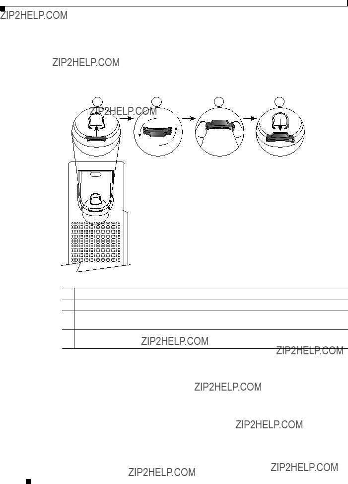
Before you mount the phone on the wall, ensure that the handset rest is such that the receiver will not slip out of the cradle (Figure E-2).
Figure E-2 Preparing the Handset Hookswitch
192897
1Remove the handset from the cradle and pull the plastic tab from the handset rest.
2Rotate the tab 180 degrees.
3Hold the tab between two fingers, with the corner notches facing you. Make sure the tab lines up evenly with the slot in the handset cradle. (Figure E-2).
4Press the tab evenly into the slot. An extension protrudes from the top of the rotated tab. Return the handset to the handset rest.
Cisco Unified IP Phone 6901 and 6911 Administration Guide for Cisco Unified Communications Manager 8.6 (SCCP and SIP)
Appendix E Installing the Wall Mount for the Cisco Unified IP Phone 6901 and 6911
Installing a Wall Mount for the Cisco Unified IP Phone 6901
Installing the Phone on Wall Mount Plate
To install the phone on the wall mount plate, follow these steps:
Procedure
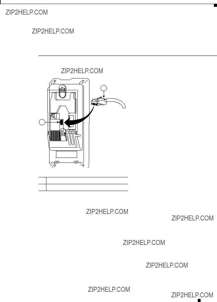
Step 1 Plug the telephone line cord (RJ45 connector) into the phone jack at the base of the phone (Figure E-3).
Figure E-3 RJ45 Connector in the Phone Jack
2
1
253655
1Network Port on the Phone
2RJ45 Connector
Cisco Unified IP Phone 6901 and 6911 Administration Guide for Cisco Unified Communications Manager 8.6 (SCCP and SIP)
Appendix E Installing the Wall Mount for the Cisco Unified IP Phone 6901 and 6911
Installing a Wall Mount for the Cisco Unified IP Phone 6901
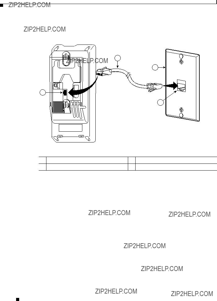
Step 2 Plug the RJ45 connector into the wall mount phone jack (Figure E-4).
Figure E-4 RJ45 Connector in the Wall Mount Jack
2
3
1
4
Cisco Unified IP Phone 6901 and 6911 Administration Guide for Cisco Unified Communications Manager 8.6 (SCCP and SIP)
Appendix E Installing the Wall Mount for the Cisco Unified IP Phone 6901 and 6911
Installing a Wall Mount for the Cisco Unified IP Phone 6901
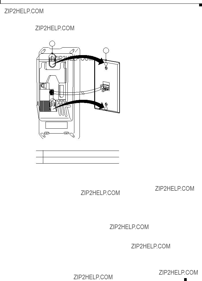
Step 3 Slip the mounting holes on the base of the wall mount plate and over the wall mount pins (Figure E-5).
1
2
253657
1Mounting Hole on the Phone
2Wall Mount Pin on the Wall Mount Plate
Cisco Unified IP Phone 6901 and 6911 Administration Guide for Cisco Unified Communications Manager 8.6 (SCCP and SIP)
Appendix E Installing the Wall Mount for the Cisco Unified IP Phone 6901 and 6911
Installing a Wall Mount for the Cisco Unified IP Phone 6901
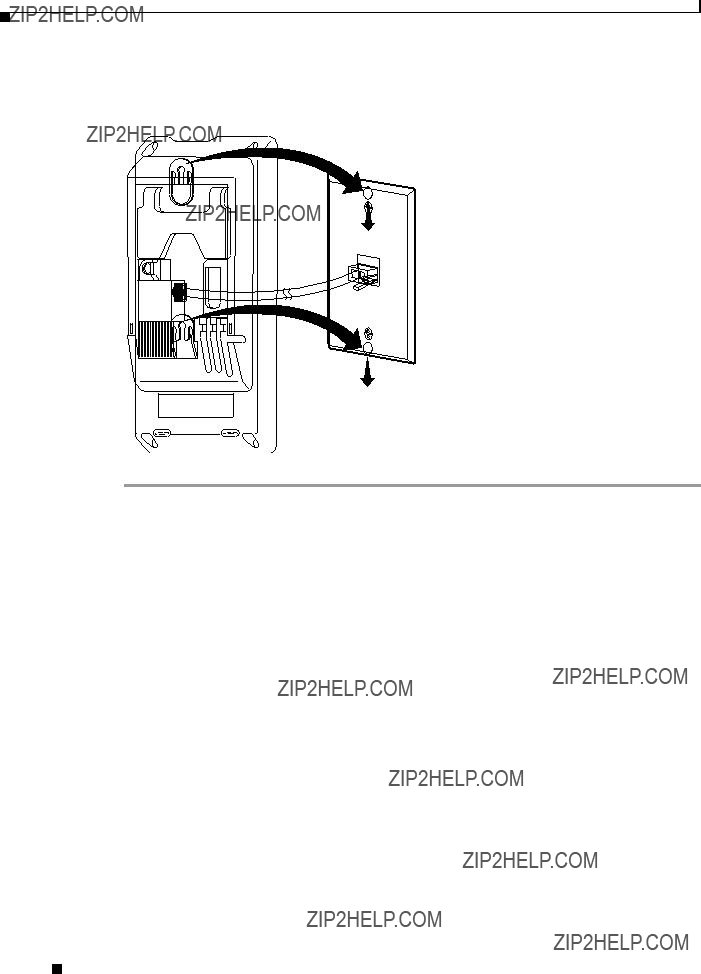
Step 4 Firmly slide the IP Phone down into place (Figure E-6).
Figure E-6 Sliding the IP Phone
253658
Cisco Unified IP Phone 6901 and 6911 Administration Guide for Cisco Unified Communications Manager 8.6 (SCCP and SIP)
Appendix E Installing the Wall Mount for the Cisco Unified IP Phone 6901 and 6911
Installing a Wall Mount for the Cisco Unified IP Phone 6911
Installing a Wall Mount for the Cisco Unified IP Phone 6911
The following section describes how to install the wall mount for use with the Cisco Unified IP Phone 6911.
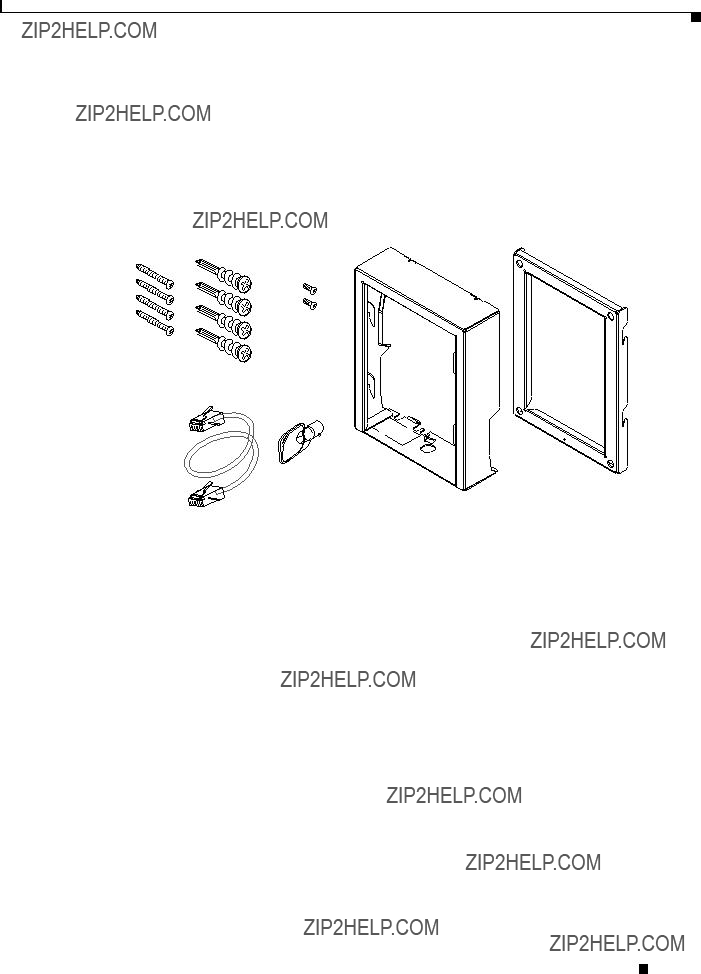
Figure E-7 shows a list of items included in the Wall Mount Kit for the Cisco Unified IP Phone 6911.
Figure E-7 Wall Mount Kit for Cisco Unified IP Phone 6911
Ethernet Lock-down
cable key
274935
The package includes the following items:
???One phone bracket
???One wall bracket
???Four 10-12x1 inch Phillips-head screws with 4 anchors
???Two 4-40x1/4 inch machine screws
???One six-inch Ethernet cable
???One key if the bracket includes the optional lock
Before You Begin
You will need these tools to install the bracket:
???#1 and #2 Phillips-head screwdrivers
???Level
You must also install an Ethernet jack for the telephone in the desired location if an Ethernet jack does not currently exist. This jack must be wired appropriately for an Ethernet connection. You cannot use a regular telephone jack. For more information on phone installation requirements and warnings, see the Setting Up the Cisco Unified IP Phone chapter.
Cisco Unified IP Phone 6901 and 6911 Administration Guide for Cisco Unified Communications Manager 8.6 (SCCP and SIP)
Appendix E Installing the Wall Mount for the Cisco Unified IP Phone 6901 and 6911
Installing a Wall Mount for the Cisco Unified IP Phone 6911
Installing the Bracket
To install the phone on the wall, follow these steps:
Procedure
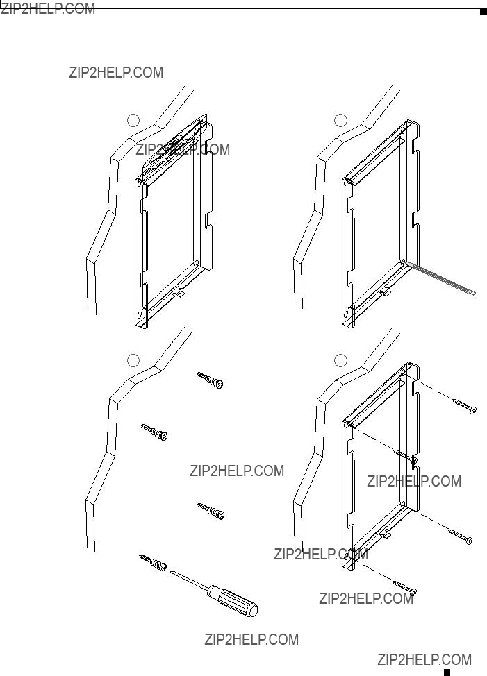
Step 1 Mount the wall bracket in the desired location (Figure E-8). You can install the wall bracket over an Ethernet jack, or you can run the Ethernet network cable to a jack nearby.
a.Use the Level to ensure the wall bracket is level, then use a pencil to mark the screw holes.
b.Using a #2 Phillips-head screwdriver, carefully center the anchor over the pencil mark and press the anchor into the wall to make markings on the wall.
c.Screw the anchor clockwise into the wall until it is seated flush.
d.Use the included screws and a #2 Phillips-head screwdriver to attach the wall bracket to the wall.
Cisco Unified IP Phone 6901 and 6911 Administration Guide for Cisco Unified Communications Manager 8.6 (SCCP and SIP)
Appendix E Installing the Wall Mount for the Cisco Unified IP Phone 6901 and 6911
Installing a Wall Mount for the Cisco Unified IP Phone 6911
Figure E-8 Mounting the Wall Bracket
AB
CD
274936
Cisco Unified IP Phone 6901 and 6911 Administration Guide for Cisco Unified Communications Manager 8.6 (SCCP and SIP)
Appendix E Installing the Wall Mount for the Cisco Unified IP Phone 6901 and 6911
Installing a Wall Mount for the Cisco Unified IP Phone 6911
Step 2 Attach the phone bracket to the IP Phone (Figure E-9).
a.Detach the handset cord (and headset cord, if there is a headset), power cord, and any other attached cords from the base of the phone.
b.Remove the label covers that are concealing the screw holes.
c.Attach the phone bracket by inserting the tabs into the mounting tabs on the phone. The phone???s ports should be accessible through the holes in the bracket.
d.Secure the phone bracket to the IP Phone with the Phillips-head screws.
e.Thread the handset cord (and headset cord, if using one). Reattach the cords and seat them in the clips incorporated into the phone body.
Figure E-9 Attaching the Phone Bracket
Screw holes
Slot for mounting tabs
274937
Appendix E Installing the Wall Mount for the Cisco Unified IP Phone 6901 and 6911
Installing a Wall Mount for the Cisco Unified IP Phone 6911
Step 3 Remove the handset wall hookswitch in the handset rest, rotate the hookswitch by 180 degrees, and reinsert the hookswitch. The hookswitch should have a lip on which the handset catches when the phone is vertical (Figure E-10).
Figure E-10 Preparing the Handset Hookswitch
192897
Appendix E Installing the Wall Mount for the Cisco Unified IP Phone 6901 and 6911
Installing a Wall Mount for the Cisco Unified IP Phone 6911
Step 4 Attach the Ethernet cable to the 10/100 SW network port and wall jack.
If you are connecting a network device (such as a computer) to the phone, attach the cable to the 10/100 PC access port.
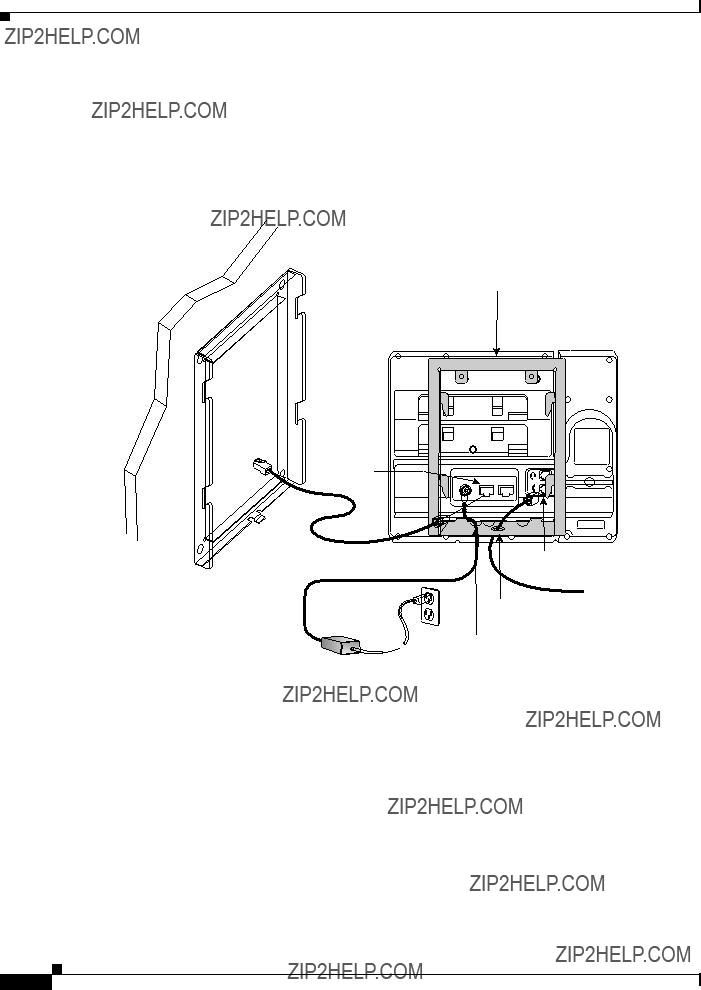
If you are using an external power supply, plug the power cord into the phone and dress the cord by clipping it into the clips incorporated into the phone body next to the 10/100 PC port (Figure E-11).
Figure E-11 Attaching the Cables
Wall bracket
Phone bracket
Network
port
274939
Handset port
AC adapter
port  Phone bracket cable access hole
U-shaped holes for cables
Appendix E Installing the Wall Mount for the Cisco Unified IP Phone 6901 and 6911
Installing a Wall Mount for the Cisco Unified IP Phone 6911
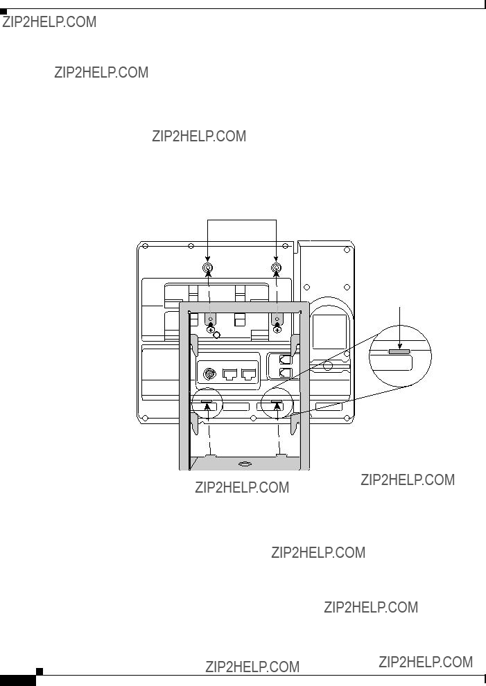
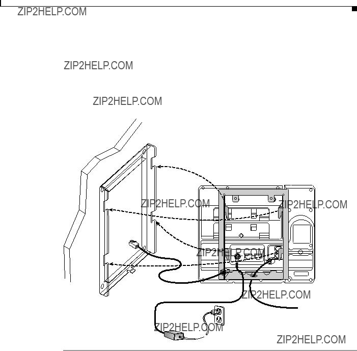
Step 5 Attach the phone to the wall bracket by inserting the tabs on the top of the phone bracket into the slots on the wall bracket. Ensure that the power cord and any other cable that does not terminate in the wall behind the bracket are positioned in one of the cable-access openings in the bottom of the bracket. The phone and wall brackets??? openings together form circular openings with room for one cable per opening (Figure E-12).
Step 6 Use the locking key to lock the phone to the wall bracket.
Figure E-12 Attaching the Phone to the Wall Bracket
275668
Appendix E Installing the Wall Mount for the Cisco Unified IP Phone 6901 and 6911
Installing a Wall Mount for the Cisco Unified IP Phone 6911